★ TRUSTED BY 321,897+ PROFESSIONALS WORLDWIDE
🏒
Trusted Business
Verified & Licensed
πŸ›‘οΈ
Virus Free Files
100% Safe Downloads
πŸ”’
Secure Payment
SSL Protected
⚑
Instant Delivery
Available Immediately
Sale!

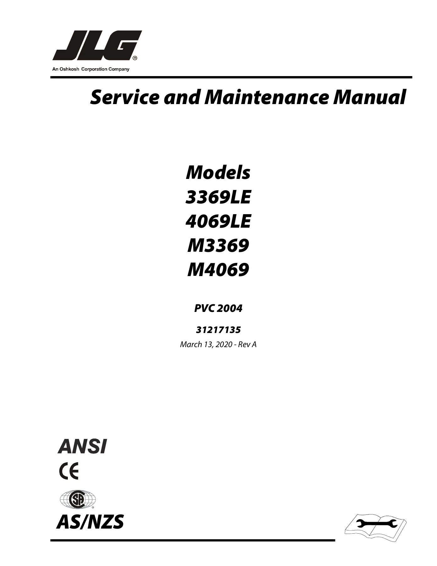
JLG 3369LE 4069LE M3369 M4069 Scissor Lift Service and Maintenance Manual – 2020

Original price was: $34.95.Current price is: $19.95.

Complete service and maintenance manual for JLG 3369LE, 4069LE, M3369, and M4069 scissor lifts. Covers specifications, hydraulic and electrical systems, JLG control system diagnostics, chassis and scissor arms, torque hubs, cylinders, and more. 158 pages. Rev A, March 2020.

⚑
Instant PDF Download
Available immediately
πŸ’Ύ
Save to Your Device
Download & keep forever
πŸ›‘οΈ
Antivirus Scanned
100% virus-free
🌍
Trusted Worldwide
175,000+ customers

Description

File Details

  • Manual Type: Service and Maintenance Manual
  • Brand: JLG
  • Models Covered: 3369LE, 4069LE, M3369, M4069
  • Document Number: 31217135
  • Revision: Rev A
  • Date: March 13, 2020
  • Language: English
  • Page Count: 158 pages
  • File Format: PDF

Chapters Covered

  • Section 1 β€” Specifications: Engine specifications, component data, dimensional data, battery charger, batteries, drive system, steer system, hydraulic pump/electric motor assembly, tires, engine (generator), capacities, pressure settings, torque specifications, cylinder specifications, major component weights, critical stability weights, lubrication, serial number locations, thread locking compound, SAE and metric fastener torque charts
  • Section 2 β€” General: Machine preparation, inspection and maintenance, pre-start inspection, pre-delivery inspection and frequent inspection, annual machine inspection, preventative maintenance, service and guidelines, safety and workmanship, cleanliness, component removal and installation, component disassembly and reassembly, pressure-fit parts, bearings, gaskets, bolt usage and torque application, hydraulic lines and electrical wiring, hydraulic system, lubrication, battery, lubrication and servicing, cylinder drift test, pins and composite bearing repair guidelines, preventive maintenance and inspection schedule
  • Section 3 β€” Chassis & Scissor Arms: Calibrations (elevation sensor, speed sensor, tilt sensor, joystick), tilt sensor removal and installation, battery maintenance and charging, battery charger (Delta-Q), battery charger troubleshooting, battery algorithms, battery temperature sensor, generator (RBS/CTS timing sequences, alternator, dynamo, control fuse, start battery, engine starter, start control relay, fuel control relay, fuel solenoid, engine oil temperature sensor, alternator output current sensor, engine speed sensor, engine low oil pressure switch, alarms and fault flash codes, priming the fuel line), supplementary fuse for APU, joystick controller, towing (disengaging/engaging), drive hub, drive brake (MICO), torque hub
  • Section 4 β€” Hydraulics: Servicing and maintenance guidelines, lubrication information, cylinders β€” theory of operation, valves β€” theory of operation, component functional description (hydraulic pump, manual descent, wear pads), motor controller β€” modes of operation, features, cylinder checking procedures, cylinder removal and installation, cylinder repair, steer cylinder removal, oscillation cylinder bleeding, oscillating axle β€” lockout cylinder test, cylinder assemblies (lift cylinder 3369LE/M3369 and 4069LE/M4069, leveling jack cylinder, steer cylinder, oscillating axle cylinder), pressure setting procedures (main relief at pump, lift relief, steer relief), drive torque hub, drive assist valve
  • Section 5 β€” JLG Control System: Hand held analyzer (connecting, using, changing access level, adjusting parameters, machine setup), PC boards, flash codes/DTC’s and descriptions, ground control circuit board (software version P1.6), J1 through J6 connector tables, analyzer flow charts
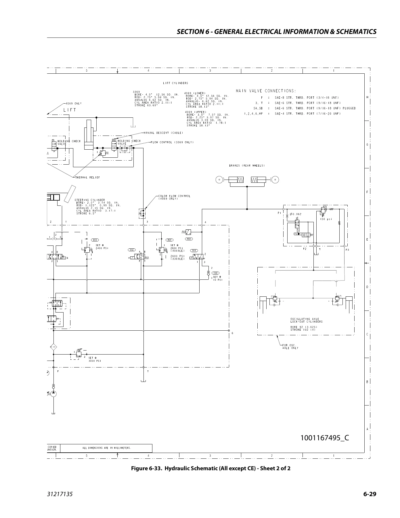
  • Section 6 β€” General Electrical Information & Schematics: General, multimeter basics (grounding, backprobing, min/max, polarity, scale, voltage measurement, continuity measurement, current measurement, continuity measurement over long distances), applying silicone dielectric compound to AMP connectors, dielectric grease application (AMP Mate-N-Lok, AMP Faston, AMP Micro-Fit, AMP Mini Fit Jr, Mini Fit Sr, DIN connectors, exceptions), AMP connector assembly and disassembly, working with Deutsch connectors (DT/DTP series, HD30/HDP20 series), electrical schematics (all except AUS, AUS), hydraulic schematics (all except CE, CE)

This JLG 3369LE 4069LE M3369 M4069 service and maintenance manual is the complete technical reference for professional and owner-level servicing of these scissor lift models. Across 158 pages, it delivers the specifications, procedures, and diagnostic information needed to maintain, troubleshoot, and repair the machine’s major systems. From the Kubota diesel generator and Delta-Q battery charger to the torque hubs, drive brakes, hydraulic cylinders, and JLG control system, the manual covers every major assembly with step-by-step instructions and factory specifications. The electrical and hydraulic schematics provide the circuit-level detail required to trace faults and verify system operation, while the flash code and DTC tables allow efficient diagnosis through the JLG analyzer.

What This Manual Helps You Do

Whether you are performing routine maintenance, diagnosing a fault, or rebuilding a major component, this manual provides the procedures and specifications to do the job correctly. Key capabilities include:

  • Calibrate critical sensors: Follow the elevation sensor, speed sensor, tilt sensor, and joystick calibration procedures to restore proper machine function after component replacement or when fault codes indicate calibration issues.
  • Diagnose electrical and control faults: Use the flash codes/DTC tables, analyzer flow charts, and connector pinout tables to pinpoint issues in the JLG control system, power module, and ground control board.
  • Service hydraulic systems: Access cylinder checking procedures, pressure setting procedures, valve component torque values, and hydraulic schematics for the lift, steer, and oscillating axle circuits.
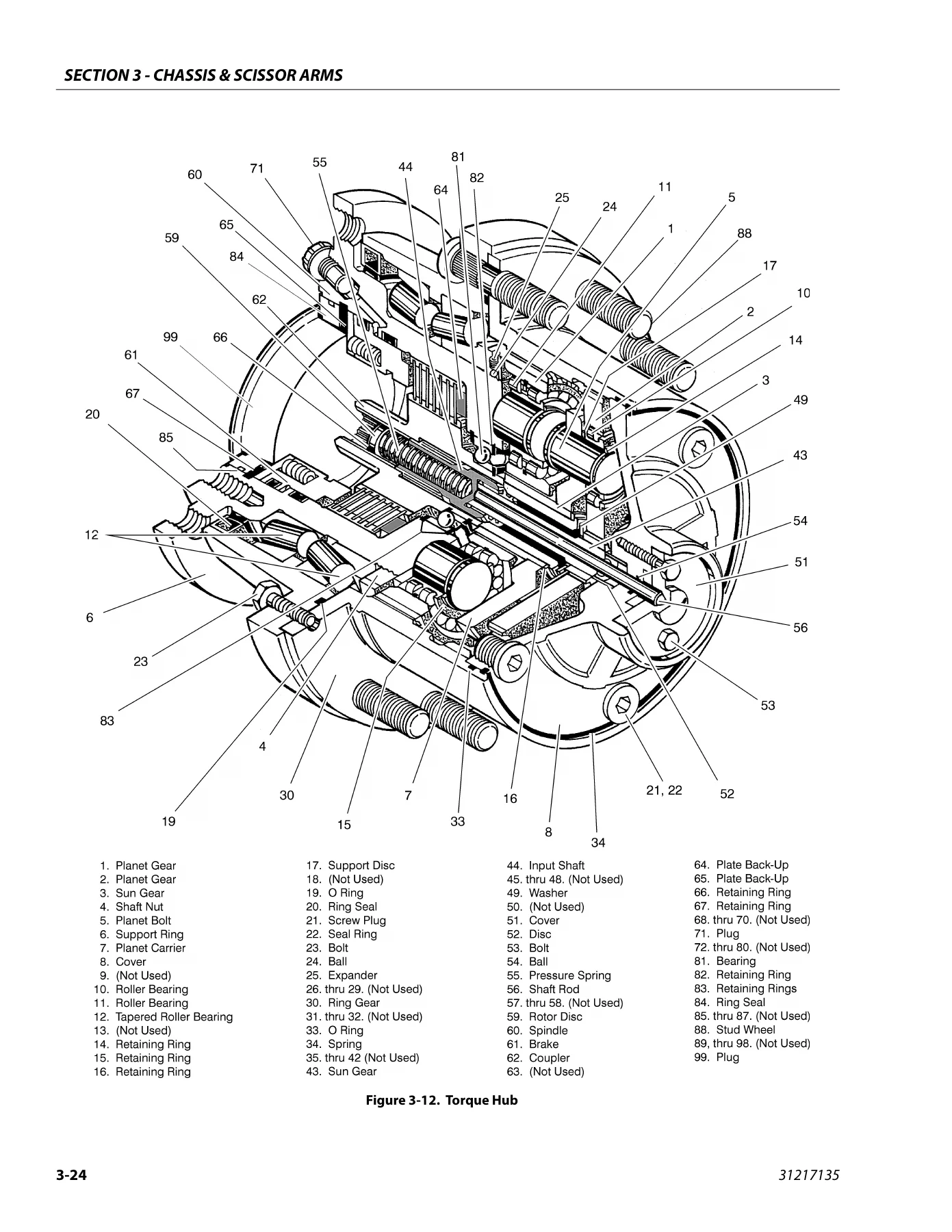
  • Repair drive and brake assemblies: Disassemble and reassemble the drive hub, MICO drive brake, and torque hub with detailed exploded views and torque specifications.
  • Maintain the generator (if equipped): Troubleshoot RBS/CTS timing sequences, flash codes, fuel line priming, and component descriptions for the Kubota diesel generator system.
  • Charge and maintain batteries: Understand Delta-Q battery charger operation, algorithm selection, fault code troubleshooting, and battery maintenance procedures.
  • Follow preventive maintenance schedules: Use the inspection and maintenance tables to establish a comprehensive service program with proper intervals.

Why This Manual Matters

JLG scissor lifts are complex machines with integrated hydraulic, electrical, and control systems. Using incorrect procedures or specifications can lead to component damage, system faults, or unsafe operating conditions. This manual provides the exact torque values, pressure settings, calibration steps, and diagnostic procedures specified by the manufacturer for the 3369LE, 4069LE, M3369, and M4069 models. The electrical and hydraulic schematics are essential for efficient troubleshooting, and the step-by-step repair procedures help ensure that components are disassembled, inspected, and reassembled correctly. For anyone responsible for maintaining these machines, this manual is an indispensable reference.

Complete PDF Bookmark Tree

Complete Bookmarks

The complete bookmarks in the β€œJLG 3369LE 4069LE M3369 M4069 Scissor Lift Service and Maintenance Manual – 2020” are as follows:

1Heading – Section A. Introduction – Maintenance Safety Precautionsp. 3
2Heading – Generalp. 3
2Heading – Hydraulic System Safetyp. 3
2Heading – Maintenancep. 3
RevisionLogHead – REVISION LOGp. 4
RevisionLogTxt – Original Issue A – March 13, 2020p. 4
1Heading – Section 1. Specificationsp. 14
2Heading – 1.1 Specificationsp. 14
2Heading – 1.2 Component Datap. 15
3Heading – Dimensional Datap. 15
3Heading – Battery Chargerp. 15
3Heading – Batteriesp. 15
3Heading – Drive Systemp. 15
3Heading – Steer Systemp. 15
3Heading – Hydraulic Pump/Electric Motor Assemblyp. 15
3Heading – Tiresp. 16
3Heading – Engine (Generator)p. 16
2Heading – 1.3 Capacitiesp. 17
2Heading – 1.4 Pressure Settingsp. 17
2Heading – 1.5 Torque Specificationsp. 17
2Heading – 1.6 Cylinder Specificationsp. 17
2Heading – 1.7 Major Component Weightsp. 17
2Heading – 1.8 Critical Stability Weightsp. 17
2Heading – 1.9 Lubricationp. 18
3Heading – Lubrication Specificationsp. 18
2Heading – 1.10 Serial Number Locationsp. 20
2Heading – 1.11 Thread Locking Compoundp. 21
2Heading – 1.12 Torque Chartsp. 22
3Heading – SAE Fastener Torque Chartp. 22
3Heading – SAE Fastener Torque Chart (Continued)p. 23
3Heading – SAE Fastener Torque Chart (Continued)p. 24
3Heading – SAE Fastener Torque Chart (Continued)p. 25
3Heading – SAE Fastener Torque Chart (Continued)p. 26
3Heading – SAE Fastener Torque Chart (Continued)p. 27
3Heading – Metric Fastener Torque Chartp. 28
3Heading – Metric Fastener Torque Chart (Continued)p. 29
3Heading – Metric Fastener Torque Chart (Continued)p. 30
3Heading – Metric Fastener Torque Chart (Continued)p. 31
1Heading – Section 2. Generalp. 32
2Heading – 2.1 Machine Preparation, Inspection, and Maintenancep. 32
3Heading – Generalp. 32
3Heading – Preparation, Inspection and Maintenancep. 32
3Heading – Pre-Start Inspectionp. 32
3Heading – Pre-Delivery Inspection and Frequent Inspectionp. 32
3Heading – Annual Machine Inspectionp. 32
3Heading – Preventative Maintenancep. 32
2Heading – 2.2 Service and Guidelinesp. 33
3Heading – Generalp. 33
3Heading – Safety and Workmanshipp. 33
3Heading – Cleanlinessp. 33
3Heading – Components Removal and Installationp. 33
3Heading – Component Disassembly and Reassemblyp. 34
3Heading – Pressure-Fit Partsp. 34
3Heading – Bearingsp. 34
3Heading – Gasketsp. 34
3Heading – Bolt Usage and Torque Applicationp. 34
3Heading – Hydraulic Lines and Electrical Wiringp. 34
3Heading – Hydraulic Systemp. 34
3Heading – Lubricationp. 34
3Heading – Batteryp. 34
3Heading – Lubrication and Servicingp. 34
2Heading – 2.3 Lubrication and Informationp. 34
3Heading – Hydraulic Systemp. 34
3Heading – Hydraulic Oilp. 35
3Heading – Changing Hydraulic Oilp. 35
3Heading – Lubrication Specificationsp. 35
2Heading – 2.4 Cylinder Drift Testp. 35
3Heading – Platform Driftp. 35
3Heading – Cylinder Driftp. 35
2Heading – 2.5 Pins and Composite Bearing Repair Guidelinesp. 36
2Heading – 2.6 Preventive Maintenance and Inspection Schedulep. 36
1Heading – Section 3. Chassis & Scissor Armsp. 41
2Heading – 3.1 Calibrationsp. 41
3Heading – Elevation Sensor Calibrationp. 41
3Heading – Speed Sensorp. 41
3Heading – Tilt Sensor Calibration:p. 41
CellNumber – 1. Ground Control Boxp. 41
CellNumber – 2. Digital Levelp. 41
CellNumbOne – 1. Ground Control Boxp. 42
CellNumber – 2. Tilt Sensorp. 42
3Heading – Joystick Calibrationp. 42
2Heading – 3.2 Tilt Sensorp. 43
3Heading – Tilt Sensor, JLG PN 4000021:p. 43
2Heading – 3.3 Battery Maintenance and Chargingp. 44
3Heading – Battery Maintenance, Quarterlyp. 44
3Heading – Optional On-Board Generatorp. 44
3Heading – Battery Charging (On Board Charger) (MAC)p. 44
3Heading – Charging Sequence of Remote LED Cardp. 45
3Heading – Battery Charger (Delta-Q)p. 46
3Heading – Battery Charger Maintenancep. 47
3Heading – Battery Charger Troubleshootingp. 47
3Heading – Battery Temperature Sensorp. 50
3Heading – Removing the Battery Boxp. 51
2Heading – 3.4 Generatorp. 52
3Heading – Timing Sequencesp. 54
3Heading – To Connect the JLG Control System Analyzer to the Generatorp. 56
3Heading – Alarms and Fault Flash Codesp. 56
3Heading – Output Current and Voltage Settingsp. 57
3Heading – Priming the Fuel Linep. 57
2Heading – 3.5 Supplementary Fuse for APUp. 58
3Heading – Tools and Materialp. 58
3Heading – Procedurep. 58
2Heading – 3.6 Joystick Controllerp. 60
3Heading – Power Controllerp. 62
2Heading – 3.7 Towingp. 62
3Heading – Disengaging for Towingp. 62
3Heading – Engaging after Towing is Completep. 63
2Heading – 3.8 Drive Hubp. 65
3Heading – Disassemblyp. 65
3Heading – Disassembly of Cover Unit (8)p. 65
3Heading – Disassembly of First Stage Planetary Assemblyp. 65
3Heading – Disassembly of the Second Stage Planet Gears (1)p. 65
CellNumbOne – 1. Retaining Screwsp. 66
CellNumber – 2. Washersp. 66
CellNumber – 3. Pressure Platep. 66
CellNumber – 4. Case Sealp. 66
CellNumber – 5. O-ringp. 66
CellNumber – 6. Backup Ringp. 66
CellNumber – 7. Pistonp. 66
CellNumber – 8. O-ringp. 66
CellNumber – 9. Backup Ringp. 66
CellNumber – 10. Shaftp. 66
CellNumber – 11. Stator Discp. 66
CellNumber – 12. Sensor Ringp. 66
CellNumber – 13. Rotor Discp. 66
CellNumber – 14. Platep. 66
CellNumber – 15. Springsp. 66
CellNumber – 16. Spring Retainerp. 66
CellNumber – 17. Retaining Ringp. 66
CellNumber – 18. Bearingp. 66
CellNumber – 19. Retaining Ringp. 66
CellNumber – 20. Dowel Pinsp. 66
CellNumber – 21. Coverp. 66
CellNumber – 22. Rotary Oil Sealp. 66
CellNumber – 23. Brake to Hub Gasketp. 66
CellNumber – 24. Brake to Motor Gasketp. 66
2Heading – 3.9 Drive Brake – MICOp. 67
3Heading – Disassemblyp. 67
3Heading – Assemblyp. 67
3Heading – Bleedingp. 67
2Heading – 3.10 Torque Hubp. 68
CellNumbOne – 1. Spindlep. 68
CellNumber – 2. Lip Sealp. 68
CellNumber – 3. Tapered Bearing Conep. 68
CellNumber – 4. Tapered Bearing Cupp. 68
CellNumber – 5. Tapered Bearing conep. 68
CellNumber – 6. Ring Gearp. 68
CellNumber – 7. Hub (Housing)p. 68
CellNumber – 8. Studp. 68
CellNumber – 9. Retaining Ring, Ext.p. 68
CellNumber – 10. Retaining Ring, Int.p. 68
CellNumber – 11. Spring (1.460, 1.500)p. 68
CellNumber – 12. Thrust Washerp. 68
CellNumber – 13. Spacerp. 68
CellNumber – 14. Seal Bootp. 68
CellNumber – 15. Thrust Spacerp. 68
CellNumber – 16. Input Carrierp. 68
CellNumber – 17. Thrust Washerp. 68
CellNumber – 18. Needle Bearingp. 68
CellNumber – 19. Planet Shaftp. 68
CellNumber – 20. Planet Gearp. 68
CellNumber – 21. Output Carrierp. 68
CellNumber – 22. Thrust Washerp. 68
CellNumber – 23. Needle Bearingp. 68
CellNumber – 24. Thrust Spacerp. 68
CellNumber – 25. Planet Shaftp. 68
CellNumber – 26. Planet Gearp. 68
CellNumber – 27. Roll Pinp. 68
CellNumber – 28. Thrust Washerp. 68
CellNumber – 29. Retaining Ring, Ext.p. 68
CellNumber – 30. Coverp. 68
CellNumber – 31. Disengage Capp. 68
CellNumber – 32. Hex Boltp. 68
CellNumber – 33. Dowel Pinp. 68
CellNumber – 34. O-ringp. 68
CellNumber – 35. Retaining Ring, Int.p. 68
CellNumber – 36. Couplingp. 68
CellNumber – 37. Input Shaftp. 68
CellNumber – 38. Input Sun Gearp. 68
CellNumber – 39. Output Sun Gearp. 68
CellNumber – 40. O-ringp. 68
CellNumber – 41. O-ringp. 68
CellNumber – 42. Retaining Ring, Ext.p. 68
3Heading – Roll Testp. 69
3Heading – Leak Test (Main Unit)p. 69
3Heading – Tightening and Torquing Boltsp. 69
3Heading – Main Disassemblyp. 70
CellNumbOne – 1. Couplingp. 70
CellNumber – 2. Retaining Ringp. 70
CellNumber – 3. Ring Gearp. 70
CellNumber – 4. Cover Subassemblyp. 70
CellNumber – 5. Washerp. 70
CellNumber – 6. First Stage Sun Gearp. 70
CellNumber – 7. Input Shaftp. 70
CellNumber – 8. Carrier Subassemblyp. 70
CellNumber – 9. Second Stage Sun Gearp. 70
CellNumber – 10. Output Stage Carrier Subassemblyp. 70
CellNumber – 11. Flat Head Boltsp. 70
CellNumber – 12. Ring Gearp. 70
CellNumber – 13. Housingp. 70
CellNumber – 14. O-Ringp. 70
CellNumber – 15. O-Ringp. 70
CellNumber – 16. Retaining Ring, Ext.p. 70
CellNumber – 17. Retaining Ring, Ext.p. 70
CellNumber – 18. ID Platep. 70
3Heading – Output Carrier Disassemblyp. 72
CellNumbOne – 1. Roll Pinp. 72
CellNumber – 2. Planet Shaftp. 72
CellNumber – 3. Carrierp. 72
CellNumber – 4. Needle Bearingsp. 72
CellNumber – 5. Thrust Washersp. 72
CellNumber – 6. Thrust Spacerp. 72
CellNumber – 7. Planet Gearsp. 72
CellNumber – 8. Thrust Washerp. 72
3Heading – Input Carrier Disassemblyp. 73
CellNumbOne – 1. Roll Pinp. 73
CellNumber – 2. Planet Shaftp. 73
CellNumber – 3. Carrierp. 73
CellNumber – 4. Planet Gearsp. 73
CellNumber – 5. Thrust Spacerp. 73
CellNumber – 6. Needle Bearingsp. 73
3Heading – Hub-Spindle Disassemblyp. 74
CellNumbOne – 1. Spindlep. 74
CellNumber – 2. Retaining Ringp. 74
CellNumber – 3. Spacerp. 74
CellNumber – 4. Bearing Conep. 74
CellNumber – 5. Bearing Cupp. 74
CellNumber – 6. Hubp. 74
CellNumber – 7. Boot Sealp. 74
CellNumber – 8. Studsp. 74
CellNumber – 9. Bearing Conep. 74
3Heading – Cover Disassemblyp. 75
CellNumbOne – 1. O-Ringp. 75
CellNumber – 2. Coverp. 75
CellNumber – 3. Thrust Washerp. 75
CellNumber – 4. Hex Head Boltsp. 75
CellNumber – 5. Disengage Capp. 75
CellNumber – 6. Disengage Rodp. 75
CellNumber – 7. O-ringp. 75
CellNumber – 8. O-ring Pipe Plugsp. 75
3Heading – Input Carrier Sub-Assemblyp. 76
3Heading – Output Carrier Sub-Assemblyp. 77
3Heading – Hub-Spindle Sub-Assemblyp. 78
3Heading – Cover Sub-Assemblyp. 79
CellNumbOne – 1. O-Ringp. 79
CellNumber – 2. Coverp. 79
CellNumber – 3. Thrust Washerp. 79
CellNumber – 4. Hex Head Boltsp. 79
CellNumber – 5. Disengage Capp. 79
CellNumber – 6. Disengage Rodp. 79
CellNumber – 7. O-ringp. 79
CellNumber – 8. O-ring Pipe Plugsp. 79
3Heading – Main Assemblyp. 80
CellNumbOne – 1. Couplingp. 80
CellNumber – 2. Retaining Ringp. 80
CellNumber – 3. Ring Gearp. 80
CellNumber – 4. Cover Subassemblyp. 80
CellNumber – 5. Washerp. 80
CellNumber – 6. First Stage Sun Gearp. 80
CellNumber – 7. Input Shaftp. 80
CellNumber – 8. Carrier Subassemblyp. 80
CellNumber – 9. Second Stage Sun Gearp. 80
CellNumber – 10. Output Stage Carrier Subassemblyp. 80
CellNumber – 11. Flat Head Boltsp. 80
CellNumber – 12. Ring Gearp. 80
CellNumber – 13. Housingp. 80
CellNumber – 14. O-Ringp. 80
CellNumber – 15. O-Ringp. 80
CellNumber – 16. Retaining ring Ext.p. 80
CellNumber – 17. Retaining Ring Rxt.p. 80
CellNumber – 18. ID Platep. 80
1Heading – Section 4. Hydraulicsp. 82
2Heading – 4.1 Servicing and Maintenance Guidelinesp. 82
3Heading – Generalp. 82
3Heading – Safety and Workmanshipp. 82
3Heading – Cleanlinessp. 82
3Heading – Component Removal and Installationp. 82
3Heading – Component Disassembly and Reassemblyp. 82
3Heading – Pressure Fit Partsp. 82
3Heading – Bearingsp. 82
3Heading – Gasketsp. 82
3Heading – Bolt Usage and Torque Applicationp. 82
3Heading – Hydraulic Lines and Electrical Wiringp. 83
3Heading – Hydraulic Systemp. 83
3Heading – Lubricationp. 83
3Heading – Batteriesp. 83
3Heading – Lubrication and Servicingp. 83
2Heading – 4.2 Lubrication Informationp. 83
3Heading – Hydraulic Systemp. 83
3Heading – Hydraulic Oilp. 83
3Heading – Changing Hydraulic Oilp. 84
3Heading – Lubrication Specificationsp. 84
2Heading – 4.3 Cylinders – Theory of Operationp. 84
2Heading – 4.4 Valves – Theory of Operationp. 84
3Heading – Control Valvesp. 84
2Heading – 4.5 Component Functional Descriptionp. 84
3Heading – Hydraulic Pumpp. 84
3Heading – Manual Descentp. 84
2Heading – 4.6 Wear Padsp. 84
2Heading – 4.7 Motor Controller – Modes of Operationp. 85
3Heading – Traction Motor (Drive)p. 85
3Heading – Pump Motor (LIft)p. 85
2Heading – 4.8 Featuresp. 85
3Heading – Traction Modep. 85
2Heading – 4.9 Cylinder Checking Proceduresp. 85
3Heading – Cylinder without Counterbalance Valves (Steer)p. 85
3Heading – Cylinders with Single Counterbalance Valve (Lift Cylinder)p. 86
3Heading – Cylinders with Duel Counterbalance Valves (Oscillating Cylinders)p. 86
2Heading – 4.10 Cylinder Removal and Installationp. 86
3Heading – Lift Cylinder Removalp. 86
3Heading – Lift Cylinder Installationp. 87
2Heading – 4.11 Cylinder Repairp. 87
3Heading – Disassemblyp. 87
3Heading – Cleaning and Inspectionp. 88
3Heading – Assemblyp. 89
2Heading – 4.12 Steer Cylinder Removalp. 91
2Heading – 4.13 Oscillation Cylinder Bleedingp. 91
3Heading – Bleeding Procedurep. 91
3Heading – Checking Oscillation Cylindersp. 91
2Heading – 4.14 Oscillating AXLE – Lockout Cylinder Test (if equipped)p. 92
3Heading – Left Side Wheel Testp. 92
3Heading – Right Side Wheel Testp. 92
2Heading – 4.15 Cylinder Assembliesp. 93
2Heading – 4.16 Pressure Setting Proceduresp. 98
3Heading – Main Relief at Pumpp. 98
3Heading – Lift Reliefp. 98
3Heading – Steer Reliefp. 98
2Heading – 4.17 Drive Torque Hubp. 99
3Heading – Disassemblyp. 99
3Heading – Assemblyp. 100
2Heading – 4.18 Drive Assist Valvep. 101
1Heading – Section 5. JLG Control Systemp. 103
2Heading – 5.1 Hand Held Analyzerp. 103
3Heading – To Connect the Hand Held Analyzerp. 103
3Heading – Using the Analyzerp. 104
3Heading – Changing the Access Level of the Hand Held Analyzerp. 105
3Heading – Adjusting Parameters Using the Hand Held Analyzerp. 106
3Heading – Machine Setupp. 106
2Heading – 5.2 PC Boardsp. 107
2Heading – 5.3 Flash Codes/DTC’s and Descriptionsp. 108
2Heading – 5.4 Ground Control Circuit Boardp. 121
3Heading – Software Version P1.6p. 121
1Heading – Section 6. General Electrical Information & Schematicsp. 126
2Heading – 6.1 Generalp. 126
2Heading – 6.2 Multimeter Basicsp. 126
3Heading – Groundingp. 126
3Heading – Backprobingp. 126
3Heading – Min/Maxp. 126
3Heading – Polarityp. 126
3Heading – Scalep. 126
3Heading – Voltage Measurementp. 127
3Heading – Continuity Measurementp. 128
3Heading – Current Measurementp. 128
3Heading – Continuity Measurement Over Long Distancesp. 129
3Heading – Requirements:p. 129
3Heading – Procedurep. 129
2Heading – 6.3 Applying Silicone Dielectric Compound to Amp Connectorsp. 129
2Heading – 6.4 Dielectric Grease Applicationp. 130
3Heading – Installationp. 130
3Heading – AMP Mate-N-Lokp. 130
3Heading – AMP Fastonp. 130
3Heading – AMP Micro-Fitp. 130
3Heading – AMP Mini Fit Jrp. 130
3Heading – Mini Fit Srp. 131
3Heading – DIN Connectorsp. 131
3Heading – Exceptionsp. 131
2Heading – 6.5 AMP Connectorp. 132
3Heading – Assemblyp. 132
3Heading – Disassemblyp. 135
3Heading – Wedge Lockp. 135
3Heading – Service – Voltage Readingp. 135
2Heading – 6.6 Working with Deutsch Connectorsp. 137
3Heading – DT/DTP Series Assemblyp. 137
3Heading – DT/DTP Series Disassemblyp. 137
3Heading – HD30/HDP20 Series Assemblyp. 138
3Heading – HD30/HDP20 Series Disassemblyp. 138
2Heading – 6.7 Electrical Schematicsp. 143


IMAGES PREVIEW

JLG 3369LE 4069LE M3369 M4069 Scissor Lift Service and Maintenance Manual - 2020 β€” PDF page 1 preview
JLG 3369LE 4069LE M3369 M4069 Scissor Lift Service and Maintenance Manual - 2020 β€” PDF page 64 preview
JLG 3369LE 4069LE M3369 M4069 Scissor Lift Service and Maintenance Manual - 2020 β€” PDF page 154 preview

Instant PDF Delivery

This JLG 3369LE 4069LE M3369 M4069 Scissor Lift Service and Maintenance Manual is delivered as an instant PDF download after purchase. No shipping, no waiting. The file can be viewed on any device β€” computer, tablet, or smartphone β€” and specific pages or sections can be printed for use in the workshop. Keep it on hand for reference during maintenance, repair, and diagnostic work.

Reviews

There are no reviews yet.

Be the first to review “JLG 3369LE 4069LE M3369 M4069 Scissor Lift Service and Maintenance Manual – 2020”

What Our Customers Say

β˜…β˜…β˜…β˜…β˜… Live reviews from customers
Loading customer reviews...
0
    0
    Your Cart
    Your cart is emptyReturn to Shop
    πŸ›’
    Recently Purchased
    πŸ•’ verified order