★ TRUSTED BY 321,897+ PROFESSIONALS WORLDWIDE
🏒
Trusted Business
Verified & Licensed
πŸ›‘οΈ
Virus Free Files
100% Safe Downloads
πŸ”’
Secure Payment
SSL Protected
⚑
Instant Delivery
Available Immediately
Sale!

JLG 1250AJP Service and Maintenance Manual 3121171 (2013) – PDF Download

Original price was: $39.95.Current price is: $24.95.

Complete JLG 1250AJP Service and Maintenance Manual, document 3121171, revised through June 2013. 606-page workshop PDF covering chassis, turntable, boom, platform, hydraulics, JLG Control System and electrical schematics for the 1250AJP aerial work platform.

⚑
Instant PDF Download
Available immediately
πŸ’Ύ
Save to Your Device
Download & keep forever
πŸ›‘οΈ
Antivirus Scanned
100% virus-free
🌍
Trusted Worldwide
175,000+ customers

Description

JLG 1250AJP Service and Maintenance Manual 3121171 (2013) – PDF Download

This is the full JLG 1250AJP Service and Maintenance Manual, document number 3121171, in its June 11, 2013 revision. It is the workshop-level reference for the 1250AJP aerial work platform and runs 606 pages across seven sections, from maintenance safety precautions and machine specifications through to the complete electrical and hydraulic schematics. Every procedure, torque figure and pressure setting in this PDF was written for the 1250AJP specifically – not a generic boom lift guide adapted from another model.

File Details

  • Manual type: Service and Maintenance Manual
  • Brand / Manufacturer: JLG Industries, Inc.
  • Model: 1250AJP
  • Document number: 3121171
  • Original issue: April 15, 2004
  • Latest revision in this file: June 11, 2013
  • Language: English
  • Page count: 606
  • File format: PDF

IMAGES PREVIEW

JLG 1250AJP Service and Maintenance Manual 3121171 (2013) - PDF Download β€” PDF page 1 preview
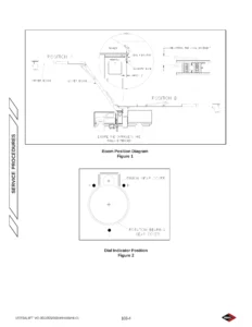
JLG 1250AJP Service and Maintenance Manual 3121171 (2013) - PDF Download β€” PDF page 24 preview
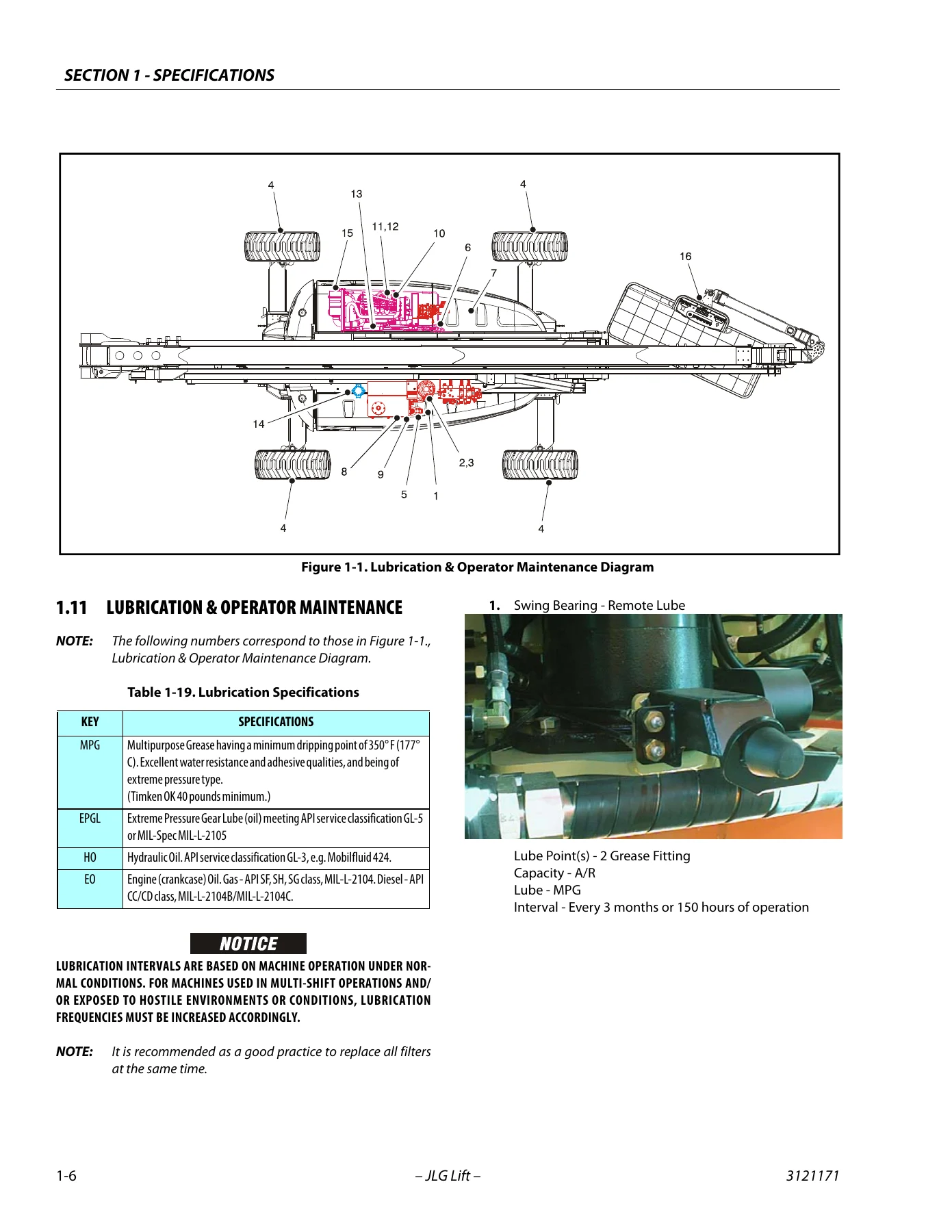
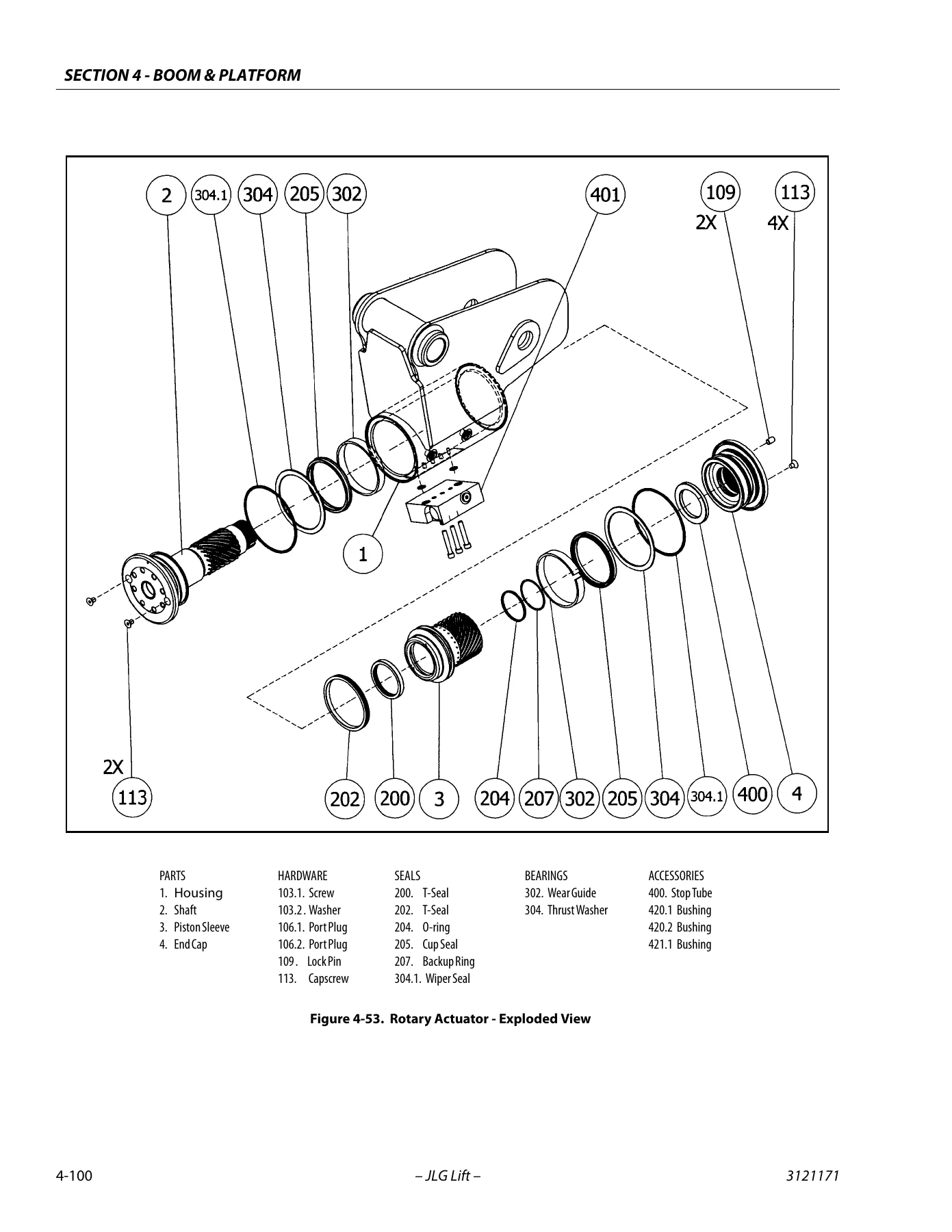
JLG 1250AJP Service and Maintenance Manual 3121171 (2013) - PDF Download β€” PDF page 340 preview

Chapters Covered

  • Section A – Introduction, Maintenance Safety Precautions: general safety, hydraulic system safety, maintenance warnings and the safe-work rules that govern every procedure in the book
  • Section 1 – Specifications: capacities, operating specifications and performance data, chassis specifications, tires, dimensional data, engine data, torque requirements, major component weights, pressure settings, hydraulic oil and lubrication/operator maintenance
  • Section 2 – General: machine preparation, inspection and maintenance, pre-start inspection, pre-delivery and frequent inspection, annual machine inspection, preventative maintenance, service and guidelines, lubrication and information, cylinder drift test, pins and composite bearing repair guidelines, welding on JLG equipment
  • Section 3 – Chassis & Turntable: tires and wheels, axle extension system, axle limit switch adjustment, drive system, steering control system, drive/steering speed control, traction control system, drive orientation system, ground control enable system, oscillating axle system, drive hub (Bonfiglioli and Reggiana Riduttori), swing drive, swing brake, swing motor, gear backlash, swing bearing, swing speed proportioning, chassis tilt indicator, rotary coupling, generator, cold weather package, engine service, Deutz EMR 2, bio fuel in Deutz engines, CAT DGC diagnostic support and trouble codes, auxiliary power system, counterweight
  • Section 4 – Boom & Platform: platform control enable, transport position sensing, drive speed cutback, drive/steer to boom interlock, jib stow system, envelope control, tower path control, automatic main boom control, electrical retrieval, hydraulic retrieval, controlled boom angle, slow down system, dual capacity system, hydraulic warm up, reduced platform heights, electronic platform leveling, main boom disassembly and assembly, tower boom installation and assembly, pin clamp procedure, transport switches, tower telescope cylinder, tower lift cylinder, main lift cylinder, main boom telescope cylinder, powertrack maintenance, hose routing, tower boom drift test, rotary actuator
  • Section 5 – Hydraulics: lubricating O-rings, cylinder repair, counterbalance valve check, hydraulic tank, hydraulic return filter, enable valves, pressure setting procedure, drive pumps, function pump, drive and function pump start-up procedures
  • Section 6 – JLG Control System: CANbus communications, calibration instructions, connecting and using the analyzer, machine setup, system test from platform and ground, calibrating steer, calibrating drive, calibrating boom valves, electronic platform leveling, calibrating platform level, calibrating tilt sensor, boom sensor calibration, Boom Control System (BCS) violation and unlock boom procedure, CANbus troubleshooting and load moment pin troubleshooting
  • Section 7 – Basic Electrical Information & Schematics: multimeter basics, applying silicone dielectric compound, AMP connectors, Deutsch connectors, wiring harness installation, turntable electrical components, 16-sheet electrical schematic and 8-sheet hydraulic schematic

What separates this manual from a parts list or a short operator booklet is the depth of the service sections. Section 3 alone walks through the complete teardown and rebuild of both the Bonfiglioli and Reggiana Riduttori wheel drive hubs, the swing drive motor and brake, and the swing bearing – including the special tools, torque sequences and Loctite callouts each step requires. Section 4 does the same for the boom assemblies and all four major cylinders, and Section 6 is a full calibration guide for the JLG Control System that lets you bring steering, drive, boom valves, tilt, platform level and every boom sensor back to factory behaviour through the hand-held analyzer.

Working On The 1250AJP

The 1250AJP combines a 125 ft platform height with a 500 lb unrestricted and 1000 lb restricted capacity, a JibPLUS side-swing rotator and a 360 degree continuous swing, and the machine’s service requirements follow from that. The envelope control system, tower path control, automatic main boom control and dual capacity system all depend on angle sensors, length sensors, a load pin and a set of limit switches that must be calibrated and cross-checked against each other. When one drifts, the machine restricts functions rather than working around the fault, so knowing the exact calibration sequence and the transport-position limits is not optional – it is how the machine is returned to service.

Complete PDF Bookmark Tree

Complete Bookmarks

The complete bookmarks in the β€œJLG 1250AJP Service and Maintenance Manual 3121171 (2013) – PDF Download” are as follows:

Section A. INTRODUCTION – MAINTENANCE SAFETY PRECAUTIONSp. 3
A Generalp. 3
B Hydraulic System Safetyp. 3
C Maintenancep. 3
Section 1. Specificationsp. 19
1.1 Capacitiesp. 19
1.2 Operating Specifications & Performance Datap. 19
1.3 Chassis Specificationsp. 19
1.4 Tiresp. 19
1.5 Dimensional Datap. 20
1.6 Engine Datap. 20
Engine Data Prior to S/N 0300127698p. 20
Engine Data S/N 0300127698 to Presentp. 20
Caterpillarp. 20
1.7 Torque Requirementsp. 21
1.8 Major Component Weightsp. 21
1.9 Pressure Settingsp. 21
1.10 Hydraulic Oilp. 22
1.11 Lubrication & Operator Maintenancep. 24
Section 2. Generalp. 39
2.1 Machine Preparation, Inspection, and Maintenancep. 39
Generalp. 39
Preparation, Inspection, and Maintenancep. 39
Pre-Start Inspectionp. 39
Pre-Delivery Inspection and Frequent Inspectionp. 39
Annual Machine Inspectionp. 39
Preventative Maintenancep. 39
2.2 Service and Guidelinesp. 40
Generalp. 40
Safety and Workmanshipp. 40
Cleanlinessp. 40
Components Removal and Installationp. 40
Component Disassembly and Reassemblyp. 41
Pressure-Fit Partsp. 41
Bearingsp. 41
Gasketsp. 41
Bolt Usage and Torque Applicationp. 41
Hydraulic Lines and Electrical Wiringp. 41
Hydraulic Systemp. 41
Lubricationp. 41
Batteryp. 41
Lubrication and Servicingp. 41
2.3 Lubrication and Informationp. 41
Hydraulic Systemp. 41
Hydraulic Oilp. 42
Changing Hydraulic Oilp. 42
Lubrication Specificationsp. 42
2.4 Cylinder Drift Testp. 42
Platform Driftp. 42
Cylinder Driftp. 43
2.5 Pins and Composite Bearing Repair Guidelinesp. 43
2.6 Welding on JLG Equipmentp. 43
Do the Following When Welding on JLG Equipmentp. 43
Do NOT Do the Following When Welding on JLG Equipmentp. 43
Section 3. Chassis & Turntablep. 49
3.1 Tires & Wheelsp. 49
Tire Inflationp. 49
Tire Damagep. 49
Tire Replacementp. 49
Wheel and Tire Replacementp. 49
Wheel Installationp. 50
3.2 Axle Extension Systemp. 51
3.3 Axle Limit Switch Adjustment Procedurep. 51
3.4 Drive Systemp. 52
3.5 Steering Control Systemp. 52
3.6 Drive/Steering Speed Controlp. 53
3.7 Traction Control Systemp. 53
3.8 Drive Orientation Systemp. 53
3.9 Ground Control Enable Systemp. 53
3.10 Oscillating Axle Systemp. 62
3.11 Oscillating Axle Bleeding Procedure and Lockout Testp. 62
Lockout Cylinder Bleedingp. 62
Oscillating Axle Lockout Testp. 63
3.12 Drive Hub (Prior to S/N 100128)p. 64
Disassemblyp. 64
Disassembly of Coverp. 64
Disassembly of the First Stage Planetary Assembly (7)p. 64
Disassembly of Second Stage Planet Gears (1)p. 64
Assembly of First Stage Planetary Assembly (7)p. 65
Assembly of End Cover Unit (8)p. 65
Final Assemblyp. 65
Initial Start-up And After Repairsp. 65
Oil Change Interval-Gear Drivep. 65
3.13 Drive Hub – Bonfiglioli (S/N 100128 to Present)p. 68
Product Identificationp. 68
Hydraulic Motor Installationp. 68
Installation of the Wheel Drive on the Machinep. 68
Start Up and Running Inp. 68
General Informationp. 69
Connecting the Brakep. 69
Filling-up the Gearbox with Lubricating Oilp. 69
Gearbox Disengagementp. 71
Maintenance Informationp. 73
Periodic Maintenancep. 73
Changing the Lubricating oilp. 73
Troubleshootingp. 74
Disassembly Informationp. 74
Disassemblyp. 74
Inspection of Partsp. 82
Assemblyp. 83
Final Test and Reinstallationp. 93
3.14 Drive Hub – Reggiana Riduttori (S/N 134389 to Present)p. 98
Symbol Nomenclaturep. 98
Toolsp. 98
Disassemblyp. 103
Assemblyp. 107
3.15 Swing Drivep. 113
Roll and Leak Testingp. 113
Tightening and Torquing Boltsp. 113
Motor Control Valve Disassemblyp. 114
Motor and Brake Disassemblyp. 115
Main Disassemblyp. 116
Hub-Shaft Disassemblyp. 117
Carrier Disassemblyp. 118
Hub-Shaft Sub-Assemblyp. 119
Carrier Sub-Assemblyp. 120
Main Assemblyp. 122
Motor and Brake Assemblyp. 124
Motor Control Valve Assemblyp. 125
3.16 Swing Brakep. 126
Pre-Installation Checksp. 126
Installationp. 127
Maintenancep. 127
Disassemblyp. 127
Examinationp. 127
Assemblyp. 127
3.17 Swing Motorp. 129
Disassembly and inspectionp. 129
Assemblyp. 136
One Piece Stator Constructionp. 143
3.18 Procedure For Setting Gear Backlashp. 144
3.19 Swing Drive Lubricationp. 145
3.20 Swing Bearingp. 146
Turntable Bearing Mounting Bolt Condition Checkp. 146
Wear Tolerancep. 149
Swing Bearing Removalp. 149
Swing Bearing Installationp. 151
Swing Bearing Torque Valuesp. 151
3.21 Swing Speed Proportioningp. 152
3.22 Chassis Tilt Indicator Systemp. 153
3.23 Rotary Couplingp. 154
3.24 Generatorp. 157
Every 250 hoursp. 157
Every 500 hoursp. 157
Overload Protectionp. 158
Inspecting Brushes, Replacing Brushes, and Cleaning Slip Ringsp. 158
inspecting brush positionp. 158
inspecting brushesp. 158
CLEANING SLIP RINGSp. 158
3.25 Cold Weather Packagep. 160
3.26 Enginep. 160
Glow Plugsp. 160
Checking Oil Levelp. 160
Changing Engine Oilp. 161
Changing the Oil Filterp. 161
Replacing the Fuel Filterp. 162
Cleaning the Fuel Strainerp. 162
Removalp. 164
Installationp. 168
3.27 Deutz EMR 2 (S/N 87575 to Present)p. 169
3.28 Bio Fuel in Deutz Enginesp. 182
Generalp. 182
Bio Fuelp. 182
Permitted bio-diesel fuelsp. 182
approved enginesp. 182
Basic conditions to be observedp. 182
Plant oilp. 183
Biological Contamination In Fuelsp. 183
Symptomsp. 183
Causep. 183
Preventive measuresp. 183
Fuel additivesp. 183
3.29 CAT DGC DIAGNOSTIC SUPPORT AND TROUBLE CODE DEFINITIONSp. 184
List of Abbreviations in this Sectionp. 186
Diagnostic Trouble Codesp. 188
CANp. 188
MIL Outputp. 188
DTC 116- ECT Higher Than Expected Stage 1p. 189
DTC 117- ECT/CHT Low Voltagep. 190
DTC 118- ECT/CHT High Voltagep. 192
DTC 122- TPS1 Signal Voltage Lowp. 194
DTC 123- TPS1 Signal Voltage Highp. 196
DTC 217- ECT Higher Than Expected 2p. 198
DTC 219- RPM Higher Than Max Allowed Governed Speedp. 199
DTC 336- Crank Signal Input Noisep. 200
DTC 337- Loss of Crank Input Signalp. 202
DTC 521- Oil Pressure Sender/Switch High Pressurep. 203
DTC 524- Oil Pressure Lowp. 204
DTC 562- Battery Voltage (VBat) Lowp. 206
DTC 563- Battery Voltage (VBat) Highp. 208
DTC 601- Microprocessor Failure – FLASHp. 210
DTC 604- Microprocessor Failure – RAMp. 212
DTC 606- Microprocessor Failure – COPp. 214
DTC 642- 5 Volt External Low Voltagep. 216
DTC 643- 5 Volt External High Voltagep. 217
DTC 1612- Microprocessor Failure – RTI 1p. 218
DTC 1613- Microprocessor Failure – RTI 2p. 219
DTC 1614- Microprocessor Failure – RTI 3p. 221
DTC 1615- Microprocessor Failure – A/Dp. 223
DTC 1616- Microprocessor Failure – interruptp. 225
DTC 1625- CAN J1939 Shutdown Requestp. 227
DTC 1626- CAN J1939 Transmit (Tx) Faultp. 228
DTC 1627- CAN J1939 Receive (Rx) Faultp. 229
DTC 1628- CAN Address Conflict Failurep. 230
DTC 1629- J1939 TSC1 Message Reciept Lossp. 232
DTC 1652- TPS1 Loss of Communicationsp. 233
DTC 2111- Unable to Reach Lower TPSp. 234
DTC 2112- Unable to Reach Higher TPSp. 236
DTC 9999- Throttle Actuator Failsafe Spring Failurep. 237
DTC to SPN/FMI Tablep. 238
3.30 Auxiliary Power Systemp. 239
3.31 Counterweightp. 239
Section 4. Boom & Platformp. 241
4.1 Platform Control Enable Systemp. 241
4.2 Transport Position Sensing Systemp. 241
4.3 Beyond Transport – Drive Speed Cutback Systemp. 241
4.4 Drive/Steer – Boom Function Interlock System (CE ONLY)p. 241
4.5 Jib Stow Systemp. 242
4.6 Envelope Control Systemp. 242
4.7 Tower Path Control Systemp. 243
4.8 Automatic Main Boom Control Systemp. 243
4.9 Electrical Retrieval Systemp. 248
4.10 Hydraulic Retrieval Systemp. 248
4.11 Controlled Boom Angle Systemp. 248
4.12 Slow Down Systemp. 248
4.13 Dual Capacity Systemp. 249
4.14 Hydraulic System Warm Upp. 249
4.15 Reduced Platform Heightsp. 249
4.16 Electronic Platform Levelingp. 250
4.17 Main Boomp. 250
Disassemblyp. 250
Assemblyp. 252
4.18 Tower Boomp. 259
Installation and Assemblyp. 259
Pin Clamp Installation Procedurep. 275
4.19 Main Boom Transport Angle Switchp. 294
Analyzer Readingsp. 294
Possible Faultsp. 295
4.20 Tower Transport Length Switchp. 295
Analyzer Readingsp. 295
Possible Faultsp. 296
4.21 Main Boom Transport Length Switchesp. 297
Analyzer Readingsp. 297
Possible Faultsp. 298
4.22 Dual Capacity Switchesp. 298
Analyzer Readingsp. 298
Possible Faultsp. 299
4.23 Tower Telescope Cylinderp. 302
Removalp. 302
Installationp. 306
4.24 Tower Lift Cylinderp. 308
Removalp. 308
Installationp. 312
4.25 Main Lift Cylinderp. 316
Removalp. 316
Installationp. 319
4.26 Main Boom Telescope Cylinderp. 320
Removalp. 320
Installationp. 324
4.27 Powertrack Maintenancep. 326
One Piece Bracket Maintenancep. 326
Two Piece Bracket Maintenancep. 328
Snap Rings and Screwsp. 329
4.28 Hose Routing Procedurep. 334
4.29 Electronic Platform Levelingp. 335
Descriptionp. 335
Normal Operationp. 335
4.30 Tower Boom Drift Testp. 337
4.31 Rotary Actuatorp. 339
Theory of Operationp. 339
Required Toolsp. 339
Disassemblyp. 342
Inspectionp. 346
Assemblyp. 346
Greasing Thrust Washersp. 351
Installing Counterbalance Valvep. 351
Testing the Actuatorp. 351
Bleeding After Installationp. 353
Section 5. Hydraulicsp. 355
5.1 Lubricating O-Rings in the Hydraulic Systemp. 355
Cup and Brushp. 355
Dip Methodp. 356
Spray Methodp. 356
Brush-on Methodp. 356
5.2 Cylinder Repairp. 357
Disassemblyp. 357
Cleaning and Inspectionp. 372
Assemblyp. 374
5.3 Counterbalance Valve Checkp. 378
5.4 Hydraulic Tankp. 379
5.5 Hydraulic Return Filterp. 380
5.6 Enable Valvesp. 399
Removalp. 399
Installationp. 399
Air Purge Procedure for Non-Calibrated Machinesp. 400
Air Purge Procedure for Calibrated Machinesp. 400
5.7 Pressure Setting Procedurep. 401
Set Up of the Function Pumpp. 401
Adjustments made at the Main Valve Bankp. 402
Adjustments Made at the Frame Valve Bankp. 406
Adjustments Made at the Platform Valve Bankp. 410
5.8 Drive Pumpsp. 411
Troubleshooting Procedurep. 411
Charge Pressure Relief Valve Adjustmentp. 414
Mechanical Centering of Pumpp. 415
Hydraulic Centering of Control Modulesp. 415
High Pressure Relief Valve Adjustmentsp. 416
Removal and inspection of charge pumpp. 416
Routine Maintenancep. 417
Removal and Installation of Shaft Sealp. 419
5.9 Function Pumpp. 421
Spare Partsp. 421
Sealing the Drive Shaftp. 422
Disassembly and Assembly of the Complete Unitp. 423
Assemblyp. 426
Adjustmentsp. 427
Tightening Torquesp. 427
Pump Control Disassembly For Cleaningp. 429
5.10 Drive & Function Pump Start Up Proceduresp. 431
Start-Up Procedurep. 431
Section 6. JLG Control Systemp. 433
6.1 Introductionp. 433
6.2 CANbus Communicationsp. 434
6.3 Calibration Instructionsp. 437
6.4 To Connect the JLG Control System Analyzerp. 450
6.5 Using the Analyzerp. 450
6.6 Changing the Access Level of the Hand Held Analyzerp. 451
6.7 Adjusting Parameters Using the Hand Held Analyzerp. 452
6.8 Machine Setupp. 452
6.9 Machine Orientation When Setting Speedsp. 462
Test Notesp. 462
6.10 System Testp. 463
Test from the Platformp. 463
Test from the Ground Stationp. 466
6.11 Calibrating Steerp. 471
6.12 Calibrating Drivep. 474
6.13 Calibrating Boom Valvesp. 477
6.14 Electronic Platform Levelingp. 480
Platform Leveling Fault Warningp. 480
Fault Responsep. 480
CAN Errorsp. 481
Additional Platform and Jib Valvesp. 481
6.15 Calibrating Platform Levelp. 482
STEP 1: SETTING THE PLATFORM VALVE MINIMUMSp. 482
STEP 2: BLEEDING THE PLATFORM VALVESp. 482
STEP 4: CALIBRATING THE PLATFORM LEVEL UP AND DOWN VALVE CRACKPOINTSp. 483
6.16 Calibrating Tilt Sensorp. 484
6.17 Boom Sensor Calibrationp. 486
General Notes:p. 486
Step 1 – Position 1p. 487
Step 2 – Position 2p. 488
Step 3 – Position 3p. 489
Step 4 – Position 4p. 490
Step 5 – Position 5p. 491
Step 6 – Position 6p. 492
Step 7 – Position 7p. 493
Step 8 – Position 8p. 494
Step 9 – Position 9p. 495
Step 10 – Position 10p. 496
Step 11 – Position 11p. 497
6.18 Boom Control System (BCS) Violationp. 498
β€œUNLOCK BOOM” Calibration Procedurep. 498
6.19 CANbus Troubleshootingp. 538
CANbus Communication Failurep. 544
Load Moment Pin Troubleshootingp. 557
Section 7. Basic Electrical Information & Schematicsp. 561
7.1 Generalp. 561
7.2 Multimeter Basicsp. 561
Groundingp. 561
Backprobingp. 561
Min/Maxp. 561
Polarityp. 561
Scalep. 561
Voltage Measurementp. 561
Resistance Measurementp. 562
Continuity Measurementp. 562
Current Measurementp. 563
7.3 Applying Silicone Dielectric Compound to Electrical Connectionsp. 563
7.4 AMP Connectorp. 564
Applying Silicone Dielectric Compound to AMP Connectorsp. 564
Assemblyp. 564
Disassemblyp. 566
Wedge Lockp. 566
Service – Voltage Readingp. 566
7.5 Deutsch Connectorsp. 568
DT/DTP Series Assemblyp. 568
DT/DTP Series Disassemblyp. 568
HD30/HDP20 Series Assemblyp. 569
HD30/HDP20 Series Disassemblyp. 569

The manual handles this properly. It documents the transport position sensing system, explains how the drive/steer interlock and oscillating axle lockout behave when the boom leaves transport, and gives the analyzer menus and access codes needed to run the system test, calibrate each sensor and clear a BCS violation. On the hydraulic side, the pressure setting procedure is broken down by valve bank – function pump standby and high-pressure relief, main valve bank swing and main telescope settings, frame valve bank axle and steer pressures, and platform valve bank level up/down and jib pressures – with the port designations you use to connect a gauge.

Engine coverage spans the Deutz BF4M2011, Deutz TD2011L4 and Caterpillar 3.4T, plus the Deutz EMR 2 electronic engine management system used from S/N 87575 onward and the CAT DGC diagnostic trouble code set. The EMR 2 and DGC sections include fault code definitions, circuit diagrams and troubleshooting flow charts, so engine-side faults can be diagnosed without a separate engine manual.

What You Can Do With This PDF

With this service and maintenance manual on hand you can perform scheduled preventative maintenance and annual inspections, troubleshoot hydraulic and electrical faults across the chassis, turntable, boom and platform, rebuild the drive hubs, swing drive and cylinders to specified torque and clearance, service the engine and generator, calibrate the JLG Control System after sensor, valve or module replacement, and work through the electrical and hydraulic schematics to trace a circuit end to end. The inspection and preventative maintenance schedule tells you what to check at pre-start, weekly, monthly, pre-delivery, frequent and annual intervals, so nothing falls out of the service cycle.

Correct procedures and correct specifications matter on a machine this size. A wheel nut torqued to the wrong value, a swing bearing bolt that was never rechecked after the first 50 hours, or a boom sensor calibrated against the wrong reference angle will all cause problems that are expensive to find later. The torque charts, pressure settings, cylinder drift limits and calibration steps in this manual are the values the machine was built to.

Instant PDF Delivery

The JLG 1250AJP Service and Maintenance Manual 3121171 is delivered as a downloadable PDF immediately after checkout – no shipping, no waiting on a courier, no physical binder to keep clean in the workshop. Open it on a laptop, tablet or phone at the machine, print the pages for the job in front of you, and keep the full 606-page reference available for every service from here on.
Reviews

There are no reviews yet.

Be the first to review “JLG 1250AJP Service and Maintenance Manual 3121171 (2013) – PDF Download”

What Our Customers Say

β˜…β˜…β˜…β˜…β˜… Live reviews from customers
Loading customer reviews...
0
    0
    Your Cart
    Your cart is emptyReturn to Shop
    πŸ›’
    Recently Purchased
    πŸ•’ verified order