★ TRUSTED BY 321,897+ PROFESSIONALS WORLDWIDE
🏒
Trusted Business
Verified & Licensed
πŸ›‘οΈ
Virus Free Files
100% Safe Downloads
πŸ”’
Secure Payment
SSL Protected
⚑
Instant Delivery
Available Immediately
Sale!

Massey Ferguson 6400 Series Tractor Electronics Service Manual – PDF Download

Original price was: $39.95.Current price is: $24.95.

Complete 1200-page Massey Ferguson 6400 series electronics service manual covering EEM Perkins and SisuDiesel electronic injection, DCC2 Dynashift and Dyna-6, Autotronic 3 and 5, EHRC linkage, Datatronic 2 and 3, SMS joystick systems, ParkLock and suspended front axles, with wiring diagrams, error codes, calibration and diagnostics.

⚑
Instant PDF Download
Available immediately
πŸ’Ύ
Save to Your Device
Download & keep forever
πŸ›‘οΈ
Antivirus Scanned
100% virus-free
🌍
Trusted Worldwide
175,000+ customers

Description

File Details

  • Manual type: Workshop service manual – Chapter 11 Electronics
  • Brand: Massey Ferguson
  • Model: 6400 series tractors (also documents 7400/8400 electronics)
  • Language: English
  • Page count: 1200
  • File format: PDF
  • Document scope: Electronic injection, transmission, linkage and front axle control systems

Chapters Covered

  • 11A10 – EEM Perkins – Description
  • GUF112 – Perkins Electronic Injection – Tests and diagnostics
  • GUF115 – Perkins Electronic Injection – Electrical Diagrams
  • 11B10 – EEM2 SisuDiesel – Description
  • GUF101 – Electronic Injection – SisuDiesel – Programming
  • GUF102 – SisuDiesel Electronic Injection – Tests and diagnostics
  • GUF103 – SisuDiesel Electronic Injection – Error codes
  • GUF105 – SisuDiesel Electronic Injection – Electrical Diagrams
  • GUF201 – DCC2 (Dynashift) – Programming and setting parameters
  • GUF203 – DCC2 (Dynashift) – Error codes
  • GUF204 – DCC2 (Dynashift) – Calibrations and constants
  • GUF231 – DCC2 (Dynashift with Autotronic 5) – Programming and setting parameters
  • GUF232 – DCC2 (Dynashift with Autotronic 5) – Tests and diagnostics
  • GUF233 – DCC2 (Dynashift with Autotronic 5) – Error codes
  • GUF234 – DCC2 (Dynashift with Autotronic 5) – Calibrations, constants and adjustments
  • GUF235 – DCC2 (Dynashift with Autotronic 5) – Electrical diagrams
  • 11C11 – DCC2 (Dyna-6) – Description
  • GUF221 – DCC2 (Dyna-6) – Programming and setting parameters
  • GUF222 – DCC2 (Dyna-6) – Tests and diagnostics
  • GUF223 – DCC2 (Dyna-6) – Error codes
  • GUF224 – DCC2 (Dyna-6) – Calibrations, constants and adjustments
  • GUF225 – DCC2 (Dyna-6) – Electrical diagrams
  • GUF31 – Autotronic 3 – Programming and setting parameters – 6400
  • GUF32 – Autotronic 3 – Tests and diagnostics – 6400
  • GUF33 – Autotronic 3 – Error codes – 6400
  • GUF34 – Autotronic 3 – Calibration and adjustments – 6400
  • GUF35 – Autotronic 3 – Electrical diagrams – 6400
  • 11D11 – Autotronic 5 – Dynashift – Description
  • GUF551 – Autotronic 5 – Dynashift – Programming and setting parameters
  • GUF552 – Autotronic 5 – Dynashift – Tests and diagnostics
  • GUF553 – Autotronic 5 – Dynashift – Error codes
  • GUF554 – Autotronic 5 – Dynashift – Calibration and adjustments
  • GUF555 – Autotronic 5 – Dynashift – Electrical diagrams
  • 11D12 – Autotronic 5 – Dyna-6 – Description
  • GUF561 – Autotronic 5 – Dyna-6 – Programming and setting parameters
  • GUF562 – Autotronic 5 – Dyna-6 – Tests and diagnostics
  • GUF563 – Autotronic 5 – Dyna-6 – Error codes
  • GUF564 – Autotronic 5 – Dyna-6 – Calibration
  • GUF565 – Autotronic 5 – Dyna-6 – Electrical diagrams
  • GUF502 – Autotronic 5 – ParkLock GPA40 (Autotronic 3) – Tests and diagnostics
  • GUF503 – Autotronic 5 – ParkLock GPA40 (Autotronic 3) – Error codes
  • GUF505 – Autotronic 5 – ParkLock GPA40 (Autotronic 3) – Electrical diagrams
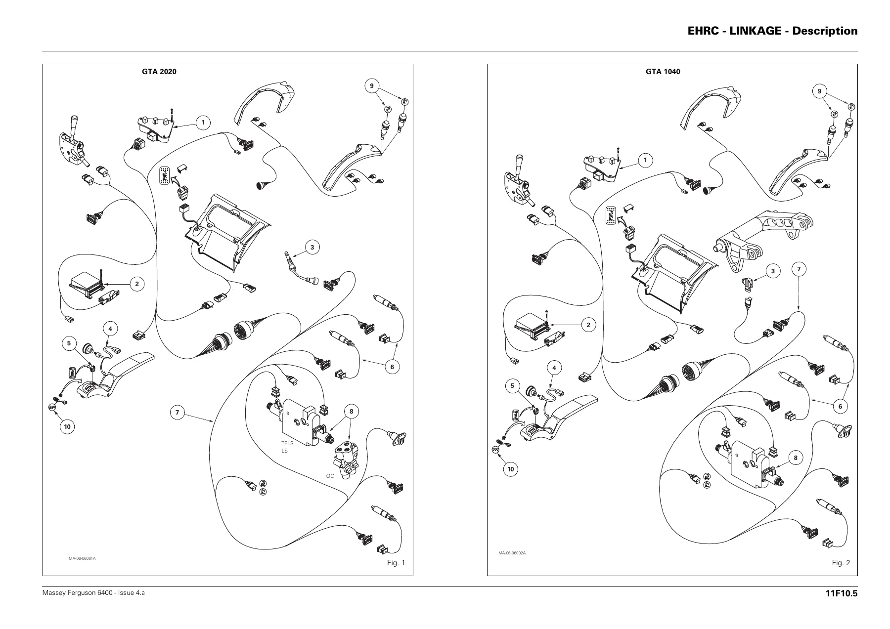
  • 11F10 – EHRC – Linkage – Description
  • GUF51 – EHRC – Linkage – Setting parameters
  • GUF52 – EHRC – Linkage – Tests and diagnostics
  • GUF53 – EHRC – Linkage – Error codes
  • GUF54 – EHRC – Linkage – Adjustments
  • GUF55 – EHRC – Linkage – Electrical diagrams – 6400/7400
  • GUF521 – Autotronic 5 – Linkage – Programming and setting parameters
  • GUF522 – Autotronic 5 – Linkage – Tests and diagnostics
  • GUF523 – Autotronic 5 – Linkage – Error codes
  • GUF524 – Autotronic 5 – Linkage – Calibration and adjustments
  • GUF525 – Autotronic 5 – Linkage – Electrical diagrams
  • GUF61 – Datatronic 2 – Programming and setting parameters
  • GUF62 – Datatronic 2 – Tests and diagnostics
  • GUF63 – Datatronic 2 – Error codes
  • GUF64 – Datatronic 2 – Calibration
  • GUF65 – Datatronic 2 – Electrical diagrams – 6400/7400
  • GUF601 – Datatronic 3 – Programming
  • GUF604 – Datatronic 3 – Calibration and adjustments
  • 11H10 – SMS – Description
  • GUF71 – SMS – JOYSTICK / FingerTIP – Setting parameters
  • GUF72 – SMS – JOYSTICK / FingerTIP – Tests and diagnostics
  • GUF73 – SMS – JOYSTICK / FingerTIP – Error codes
  • GUF74 – SMS – JOYSTICK – Settings
  • GUF75 – SMS – JOYSTICK / FingerTIP – Electrical diagrams
  • GUF581 – Autotronic 5 – CARRARO suspended front axle – Programming
  • GUF582 – Autotronic 5 – CARRARO suspended front axle – Tests and diagnostics
  • GUF583 – Autotronic 5 – CARRARO suspended front axle – Error codes
  • GUF584 – Autotronic 5 – CARRARO suspended front axle – Calibration and adjustments
  • GUF585 – Autotronic 5 – CARRARO suspended front axle – Electrical diagrams
  • 11H10 – Autotronic 5 – DANA Suspended front axle – Description
  • GUF541 – Autotronic 5 – DANA suspended front axle – Programming and setting parameters
  • GUF542 – Autotronic 5 – DANA suspended front axle – Tests and diagnostics
  • GUF543 – Autotronic 5 – DANA suspended front axle – Error codes
  • GUF544 – Autotronic 5 – DANA suspended front axle – Calibration and adjustments
  • GUF545 – Autotronic 5 – DANA suspended front axle – Electrical diagrams

Complete PDF Bookmark Tree

Complete Bookmarks

The complete bookmarks in the β€œMassey Ferguson 6400 Series Tractor Electronics Service Manual – PDF Download” are as follows:

Contents
01 – Introduction – Specifications
02 – Splitting the tractor
03 – Engine
05 – Gearbox
06 – Rear axle
07 – Power take off
08 – Front axle
09 – Hydraulics
10 – Electrical equipment
11 – Electronics
11A10 – EEM Perkins – Description
A . Presentation
B . Components on the engine
C . Communication Tractor / Engine
D . Cab controls
A . Configuration
B . Programming
GUF112 – Perkins ELECTRONIC INJECTION – Tests and diagnostics
A . Tests and diagnostics
A . Reading error codes
B . List of error codes
C . Reaction of the system when an error code occurs
D . Reaction of the system when an error code with an event occurs
GUF115 – Perkins ELECTRONIC INJECTION – Electrical Diagrams
A . Perkins engine harness
B . General Tractor with DCC2
C . Electrical diagrams for tractors with DCC2
D . General Tractor without DCC2
E . Electrical diagrams for tractors without DCC2
11B10 – EEM2 SisuDiesel – Description
A . Presentation
B . Components on the engine
C . Communication Tractor / Engine
D . Cab controls
GUF101 – ELECTRONIC INJECTION – SisuDiesel – Programming
A . Matching serial numbers
B . Location of software for WinEEM3
C . List of the various engine software
GUF102 – SisuDiesel ELECTRONIC INJECTION – Tests and diagnostics
A . Tests and diagnostics
GUF103 – SisuDiesel ELECTRONIC INJECTION – Error codes
A . Reading error codes
B . List of error codes
C . EEM2 troubleshooting
D . EEM2 sensor diagnostics
E . EEM2 controller diagnostics
F . Fuel injection pump diagnostics
G . Electrical diagrams
H . Component characteristics
GUF105 – SisuDiesel ELECTRONIC INJECTION – Electrical Diagrams
A . General
B . SisuDiesel engine harness
C . Electrical diagrams on the tractor
GUF201 – DCC2 (Dynashift) – Programming and setting parameters
A . Setting parameters
B . Programming
GUF203 – DCC2 (Dynashift) – Error codes
A . Reading error codes
B . List of error codes
C . Analysing error codes
GUF204 – DCC2 (Dynashift) – Calibrations and constants
A . Calibrating the ground speed (level 0)
B . Calibrating the throttle pedal potentiometer
C . Input at level 2 – CAL 2
D . Input at level 3 – CAL 3
E . Diagnostic mode
GUF231 – DCC2 (Dynashift with Autotronic 5) – Programming and setting parameters
A . Setting parameters
B . Programming
GUF232 – DCC2 (Dynashift with Autotronic 5) – Tests and diagonostics
A . Switches on DCC2
GUF233 – DCC2 (Dynashift with Autotronic 5) – Error codes
A . Reading error codes
B . List of error codes
C . Analysing error codes
D . Analysing other error codes
GUF234 – DCC2 (Dynashift with Autotronic 5) – Calibrations, constants and adjustments
A . Calibrating the ground speed (level 0)
B . Calibrating the throttle pedal potentiometer
C . Input at level 2 – CAL 2
D . Input at level 3 – CAL 3
E . Diagnostic mode
F . Adjusting the manoeuvring pedal
GUF235 – DCC2 (Dynashift with Autotronic 5) – Electrical diagrams
A . General
B . Electrical diagrams
11C11 – DCC2 (Dyna-6) – Description
A . General
B . Description
C . Allocation of DCC2 pins
GUF221 – DCC2 (Dyna-6) – Programming and setting parameters
A . Setting parameters
B . Programming
GUF222 – DCC2 (Dyna-6) – Tests and diagnostics
A . Switches on DCC2
GUF223 – DCC2 (Dyna-6) – Error codes
A . Reading error codes
B . List of error codes
C . Analysing error codes
D . Analysing other error codes
GUF224 – DCC2 (Dyna-6) – Calibrations, constants and adjustments
A . Calibrating the ground speed (level 0)
B . Calibrating the throttle pedal potentiometer
C . Calibrating the armrest lever
D . Input at level 2 – CAL 2
E . Input at level 3 – CAL 3
F . Diagnostic mode
G . Adjusting the manoeuvring pedal
GUF225 – DCC2 (Dyna-6) – Electrical diagrams
A . General
B . Electrical diagrams
GUF31 – AUTOTRONIC 3 – Programming and setting parameters – 6400
A . Programming
B . Setting parameters
GUF32 – AUTOTRONIC 3 – Tests and diagnostics – 6400
A . Autotronic 3 statuses
B . Safety Function
C . Gearbox function
D . Front Axle function
E . Differential function
F . Power Take-Off function
GUF33 – AUTOTRONIC 3 – Error codes – 6400
A . Reading error codes
B . List of error codes
GUF34 – AUTOTRONIC 3 – Calibration and adjustments – 6400
A . Calibrating the Power Shuttle
B . Adjusting the Power Shuttle progressive shifting
C . Calibrating the throttle pedal potentiometer
D . Adjusting the manoeuvring pedal
GUF35 – AUTOTRONIC 3 – Electrical diagrams – 6400
A . General
B . Electrical diagrams
C . Layout of components
11D11 – AUTOTRONIC 5 – Dynashift – Description
A . General
B . Autotronic 5 automatic responses
C . Automatic Dynashift operating mode
D . Allocation of Autotronic 5 transmission controller pins
GUF551 – AUTOTRONIC 5 – Dynashift – Programming and setting parameters
A . Programming
B . Saving to a file
C . Setting parameters
GUF552 – AUTOTRONIC 5 – Dynashift – Tests and diagnostics
A . Gearbox function
B . Front Axle function
C . Differential function
D . Power Take-Off function
E . ParkLock function
GUF553 – AUTOTRONIC 5 – Dynashift – Error codes
A . Reading error codes
B . List of error codes
C . Analysing components and their error codes
D . Analysing other error codes
GUF554 – AUTOTRONIC 5 – Dynashift – Calibration and adjustments
A . Calibrating the PowerShuttle
B . Adjusting the Power Shuttle progressive shifting
GUF555 – AUTOTRONIC 5 – Dynashift – Electrical diagrams
A . General
B . Electrical diagrams
C . Layout of components
11D12 – Autotronic 5 – Dyna 6 – Description
A . General
B . Description of components
C . Autotronic 5 Transmission status summary
D . Creeper function
E . 4WD function
F . Differential lock function
G . Power take-off function
H . Power Shuttle function
I . Autodrive function
J . Allocation of Autotronic 5 Transmission controller pins
GUF561 – AUTOTRONIC 5 – Dyna-6 – Programming and setting parameters
A . Programming
B . Saving to a file
C . Setting parameters
GUF562 – AUTOTRONIC 5 – Dyna-6 – Tests and diagnostics
A . Gearbox function
B . Front axle function
C . Differential function
D . Power take-off function
E . High-pressure braking function (50 kph)
GUF563 – Autotronic 5 – Dyna-6 – Error codes
A . Reading error codes
B . List of error codes
C . Analysing components and their error codes
D . Analysing other error codes
GUF564 – AUTOTRONIC 5 – Dyna-6 – Calibration
A . Power Shuttle calibration
B . Calibrating the Senstronic sensor
GUF565 – AUTOTRONIC 5 – Dyna-6 – Electrical diagrams
A . General
B . Electrical diagrams
GUF502 – AUTOTRONIC 5 – ParkLock GPA40 (Autotronic 3) – Tests and diagnostics
A . Autotronic 5 statuses
B . Diagnostics screen
GUF503 – AUTOTRONIC 5 – ParkLock GPA40 (Autotronic 3) – Error codes
A . List of error codes
GUF505 – AUTOTRONIC 5 – ParkLock GPA40 (Autotronic 3) – Electrical diagrams
A . General
B . Electrical diagrams
11F10 – EHRC – LINKAGE – Description
A . Description
B . Console
GUF51 – EHRC – Linkage – Setting parameters
A . Access to the parameters display
B . List of parameters
C . Access to the table of constants
GUF52 – EHRC – Linkage – Tests and diagnostics
A . Electronic Linkage functions
B . Dual Control function and TIC
GUF53 – EHRC – Linkage – Error codes
A . Reading error codes
B . List of error codes
GUF54 – EHRC – Linkage – Adjustments
A . Adjusting the position sensor
B . Setting Dual Control Parameters
GUF55 – EHRC – Linkage – Electrical diagrams – 6400/7400
A . General
B . Electrical diagrams
GUF521 – AUTOTRONIC 5 – Linkage – Programming and setting parameters
A . Programming
B . Saving to a file
C . Setting parameters
D . Table of constants
GUF522 – AUTOTRONIC 5 – Linkage – Tests and diagnostics – MF6400/7400/8400
A . Autotronic 5 statuses
B . Electronic Linkage functions
GUF523 – AUTOTRONIC 5 – Linkage – Error codes – MF6400/7400/8400
A . Reading error codes
B . List of error codes
C . Analysing components and their error codes
GUF524 – AUTOTRONIC 5 – Linkage – Calibration and adjustments
A . Adjusting the position sensor
B . Calibrating the linkage
GUF525 – AUTOTRONIC 5 – Linkage – Electrical diagrams – MF6400/7400/8400
A . General
B . Electrical diagrams
GUF61 – DATATRONIC 2 – Programming and setting parameters
A . Programming
B . Setting parameters
C . Selecting the language
GUF62 – DATATRONIC 2 – Tests and diagnostics
A . Tests and diagnostics
GUF63 – DATATRONIC 2 – Error codes
A . Reading error codes
B . List of error codes which can be displayed on Datatronic 2
GUF64 – DATATRONIC 2 – Calibration
A . Calibration
GUF65 – DATATRONIC 2 – Electrical diagrams – 6400 / 7400
A . General
B . Electrical diagrams
GUF601 – DATATRONIC 3 – Programming
A . Programming
B . Setting parameters
GUF604 – DATATRONIC 3 – Calibration and adjustments
A . General
B . Adjusting the sensor
C . Connecting to the tractor
D . Front Dual Control calibration
E . Rear Dual Control calibration
F . Trailed Implement Control (TIC) calibration
GUF605 – DATATRONIC 3 – Electrical diagrams
A . General
B . Electrical diagrams (Dyna-VT)
C . Electrical diagrams (6400)
11H10 – SMS – Description
A . General
B . Description of SMS components (Fig. 2)
C . Operation and troubleshooting without a tester
D . SMS error codes
E . Disassembling and reassembling the Joystick
F . Replacing ON / OFF or Memory switches
GUF71 – SMS – JOYSTICK / FingerTIP – Setting parameters
A . Description
B . Setting parameters
GUF72 – SMS – JOYSTICK/FingerTIP – Tests and diagnostics
A . Joystick tests and diagnostics
B . FingerTIP tests and diagnostics
GUF73 – SMS – JOYSTICK / FingerTIP – Error codes
A . Operation and troubleshooting
B . Reading error codes with EHRC linkage calculator
C . Reading error codes with Autotronic 5 linkage calculator
D . Display of error codes
E . Reading error codes stored by the electrohydraulic spool valves
F . List of error codes
GUF74 – SMS – JOYSTICK – Settings
A . Joystick calibration
B . Adjusting EHS valve control levers
GUF75 – SMS – JOYSTICK – Electrical diagrams – EHRC linkage
A . General
B . Electrical diagrams
GUF75 – SMS – JOYSTICK/FingerTIP – Electrical diagrams – Auto 5 linkage
A . General
B . Electrical diagrams
GUF581 – AUTOTRONIC 5 – CARRARO suspended front axle – Programming
A . Programming
B . Saving to a file
GUF582 – AUTOTRONIC 5 – CARRARO suspended front axle – Tests and diagnostics
A . Diagnostics screen
GUF583 – AUTOTRONIC 5 – CARRARO Suspended front axle – Error codes
A . Reading error codes
B . List of error codes
C . Analysing components and their error codes
GUF584 – AUTOTRONIC 5 – CARRARO suspended front axle – Calibration and adjustments
A . Adjustment
B . Calibration
GUF585 – AUTOTRONIC 5 – CARRARO suspended front axle – Electrical diagrams
A . General
B . Electrical diagrams – CARRARO suspended front axle
C . Layout of CARRARO components
11H10 – Autotronic 5 – DANA Suspended front axle – Description
A . General
B . Operating mode
C . Regulation in suspension mode
D . Autotronic 5 connector
GUF541 – AUTOTRONIC 5 – DANA suspended front axle – Programming and setting parameters
A . Programming
B . Saving to a file
C . Setting parameters
GUF542 – AUTOTRONIC 5 – DANA suspended front axle – Tests and diagnostics
A . Diagnostics screen
GUF543 – AUTOTRONIC 5 – DANA suspended front axle – Error codes
A . Reading error codes
B . List of error codes
C . Analysing components and their error codes
GUF544 – AUTOTRONIC 5 – DANA suspended front axle – Calibration and adjustments
A . Settings
B . Calibration
GUF545 – AUTOTRONIC 5 – DANA suspended front axle – Electrical diagrams
A . 5400 electrical diagrams
B . 6400-7400-8400 electrical diagrams
12 – Cab and equipment
13 – Accessories

This Massey Ferguson 6400 Series Tractor Electronics Service Manual is the complete Chapter 11 electronics volume for the 6400 series workshop documentation, running to 1200 pages of factory-level diagnostic, programming, calibration and wiring information. It covers every major electronic control system fitted across the 6400 platform – Perkins and SisuDiesel electronic injection, Dynashift and Dyna-6 transmissions through the DCC2 and Autotronic 3 / Autotronic 5 controllers, EHRC and Autotronic 5 electronic linkage, Datatronic 2 and Datatronic 3 monitoring, SMS Joystick and FingerTIP spool valve management, ParkLock, and both CARRARO and DANA suspended front axles. Each subsystem is documented from first principles through to the exact error code that triggers a lamp on the dash, so a technician has a complete path from symptom to repair.

IMAGES PREVIEW

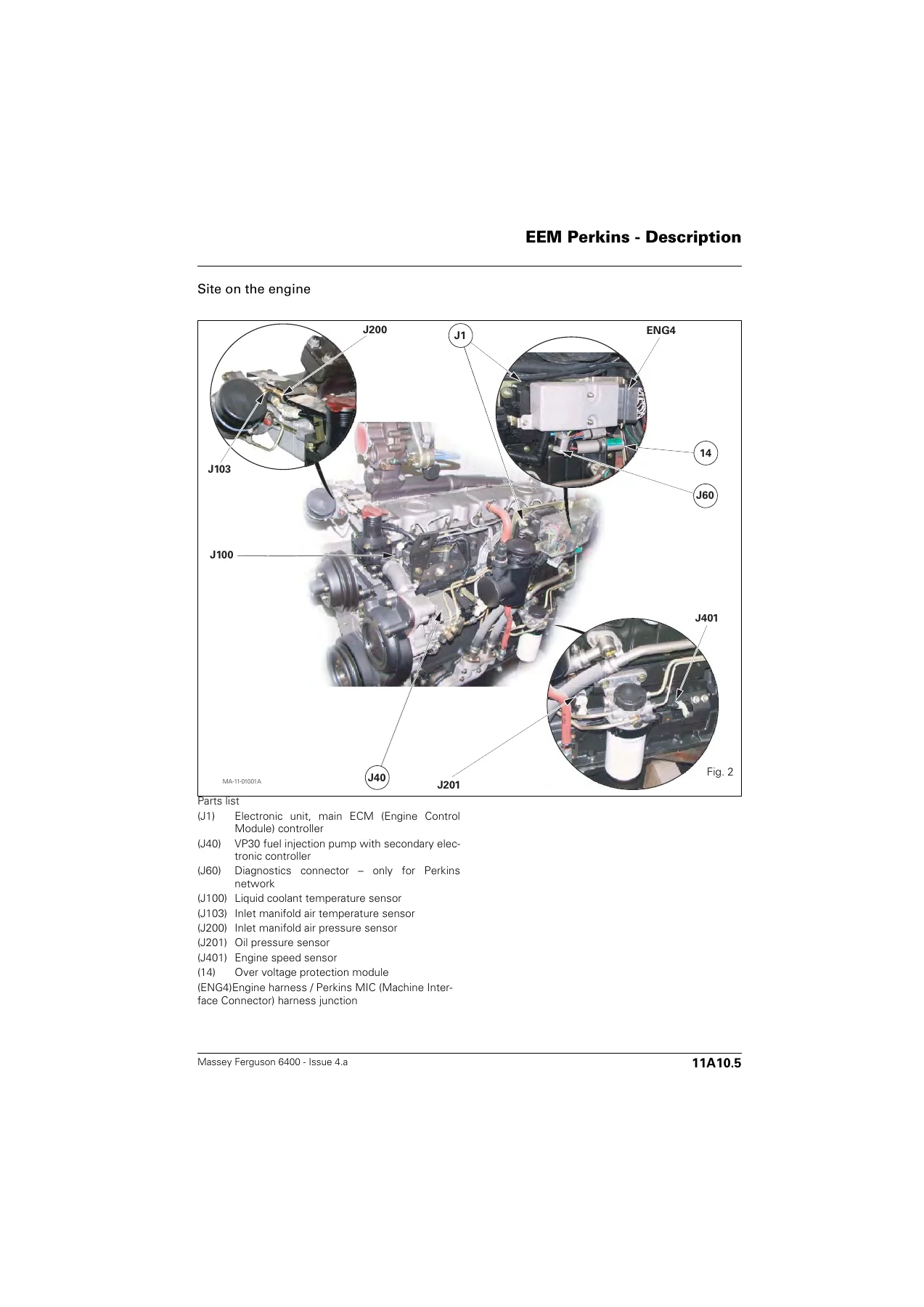
Massey Ferguson 6400 Series Tractor Electronics Service Manual - PDF Download β€” PDF page 9 preview
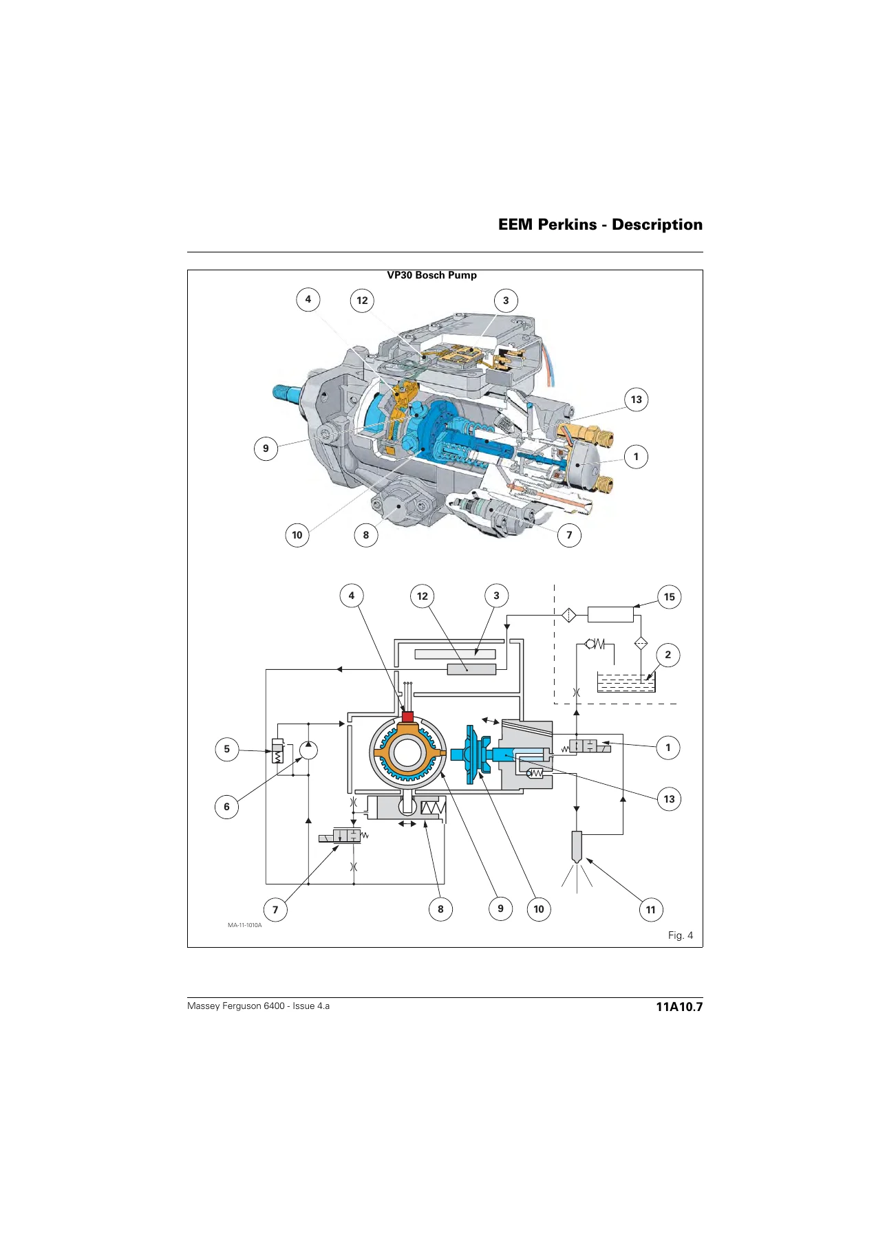
Massey Ferguson 6400 Series Tractor Electronics Service Manual - PDF Download β€” PDF page 11 preview
Massey Ferguson 6400 Series Tractor Electronics Service Manual - PDF Download β€” PDF page 817 preview

What This Electronics Manual Gives You

The PDF is arranged so that each electronic system is covered end to end: description, setting parameters, tests and diagnostics, error codes, calibration and adjustments, and electrical diagrams. For the injection side you get the full EEM Perkins and EEM2 SisuDiesel content, including the VP30 Bosch pump internal description, sensor diagnostics and the DTC list behind every fault lamp. For transmissions you get the DCC2 (Dynashift) and DCC2 (Dyna-6) programming and parameter tables, the Autotronic 3 and Autotronic 5 calibration procedures, PowerShuttle calibration, Powershift module and range solenoid diagnostics, and the full CAN network wiring for each option combination. For linkage you get the EHRC and Autotronic 5 linkage parameter codes, position sensor adjustment, Dual Control and TIC calibration, and the error codes that lock the console. For SMS you get Joystick and FingerTIP valve parameter setting, spool valve error codes, and the calibration that restores float and flow-rate memory. For front axles you get both the CARRARO and DANA Autotronic 5 suspended axle programming, diagnostics, error codes, sensor adjustment and calibration. ParkLock GPA40 is covered in full, including the diagnostics and error codes for the Autotronic 3 configuration.

Electrical Diagrams and Diagnostics

The wiring content is one of the strongest reasons to own this manual. The electrical diagram chapters show the engine harness, general tractor harness layouts, CAN network topologies for every Autotronic 3, Autotronic 4, Autotronic 5 and Dyna-6 variant, DCC2 pin allocations, Autotronic 5 controller pinouts, Datatronic 2 and 3 connectors, SMS joystick and spool valve harnesses, ParkLock harnesses, and suspended front axle circuits. Pin-by-pin connector tables accompany the diagrams, with wire colours and pin functions labelled so a circuit can be traced from the ECU to the sensor or solenoid without guesswork. When a fault code points to an open circuit, short to supply or short to ground, the relevant diagram is in the same document.

Programming, Calibration and Service Tools

Procedures are written around the AGCO Wintest and EST service tools and the WinEEM3 SisuDiesel diagnostic application. The manual explains how to match a new injection pump serial number to the ECU, how to download engine software, how to set the DCC2 label code, how to programme an Autotronic 5 controller with the correct transmission or linkage software, how to calibrate the PowerShuttle at the correct transmission oil temperature, how to calibrate EHRC linkage travel, and how to calibrate a suspended front axle through the mode switch. These are the tasks that turn a laptop and a CAN interface into a full dealer-level diagnostic session, and they are documented with the exact conditions, temperature windows and failure modes that stop a calibration from completing.

Who This Manual Is For

This 6400 series electronics manual suits independent mechanics, fleet workshops, agri-service technicians and owner-operators who already have the mechanical side of the 6400 platform covered but need the electronic layer. It is also the reference for anyone maintaining a 6400, 7400 or 8400 series tractor where the DCC2, Autotronic 5, EHRC, SMS or suspended front axle is shared across the range. If a fault lamp is on, a transmission will not calibrate, a linkage console is locked, a Joystick has lost its flow-rate memory, or a suspended front axle is sitting on its bump stop, the diagnostic path is in this document.

Instant PDF Delivery

The Massey Ferguson 6400 Series Tractor Electronics Service Manual is delivered as an instant PDF download once payment is complete – no shipping, no waiting for a disc or a printed binder. It opens on any device with a PDF reader, can be searched and printed, and can be kept on a workshop laptop or tablet next to the Wintest diagnostic screen. Because it is the full 1200-page Chapter 11 electronics volume, all of the programming tables, error code lists, calibration procedures and wiring diagrams stay together in a single searchable file instead of being split across multiple documents.
Reviews

There are no reviews yet.

Be the first to review “Massey Ferguson 6400 Series Tractor Electronics Service Manual – PDF Download”

What Our Customers Say

β˜…β˜…β˜…β˜…β˜… Live reviews from customers
Loading customer reviews...
0
    0
    Your Cart
    Your cart is emptyReturn to Shop
    πŸ›’
    Recently Purchased
    πŸ•’ verified order