
JLG X14J X17J X19J X23J X390AJ X550AJ X700AJ Service & Maintenance Manual 3121448 Rev C 2023
$44.95 Original price was: $44.95.$26.95Current price is: $26.95.
Complete 600-page JLG Service and Maintenance Manual covering X14J, X17J, X19J, X23J, X390AJ, X550AJ and X700AJ compact crawler boom lifts. Includes specifications, inspection and maintenance procedures, track and undercarriage service, engine repair information, boom and platform work, hydraulic repair and schematics, JLG control-system calibration, CANBUS diagnostics and detailed electrical wiring diagrams.
Description
JLG X14J X17J X19J X23J X390AJ X550AJ X700AJ Service & Maintenance Manual 3121448 Rev C 2023
This 600-page JLG X14J X17J X19J X23J X390AJ X550AJ X700AJ Service & Maintenance Manual 3121448 Rev C 2023 is a detailed service reference for the compact crawler boom lift models identified on the manual cover. It brings together machine specifications, inspection requirements, mechanical repair procedures, engine service information, hydraulic testing and repair, control-system calibration, CANBUS information and electrical schematics in one extensive document.
The manual is particularly useful where work extends beyond routine servicing. Major sections deal with rubber tracks and undercarriage components, drive gear motors, swing drive, multiple gasoline and diesel engine installations, boom disassembly, hydraulic cylinders and pumps, pressure adjustment, platform controls, electronic modules, sensors and machine wiring. Numerous procedures are supported by component illustrations, exploded views, photographs, hydraulic diagrams and wiring schematics.
File Details
- Manual type: Service and Maintenance Manual
- Brand: JLG
- Models: X14J, X17J, X19J, X23J, X390AJ, X550AJ, X700AJ
- Language: English
- Pages: 600
- File format: PDF
- Part number: 3121448
- Revision: Rev C
- Revision date: February 3, 2023
The revision log records the original issue dated June 6, 2012, a revision dated June 29, 2018, and the February 3, 2023 revision represented by this Rev C manual.
Machine, Engine and Service Coverage
The JLG X14J X17J X19J X23J X390AJ X550AJ X700AJ service manual covers a broad range of configurations within this compact crawler family. Engine information in the document includes the Honda GX270 and GX390 series, Honda iGX440, Hatz 1B30 and 1B40, and Perkins 402D engine material. The engine sections go substantially beyond identification data: the manual contains specification tables, service values, maintenance schedules and component-level procedures for the power units included in the document.
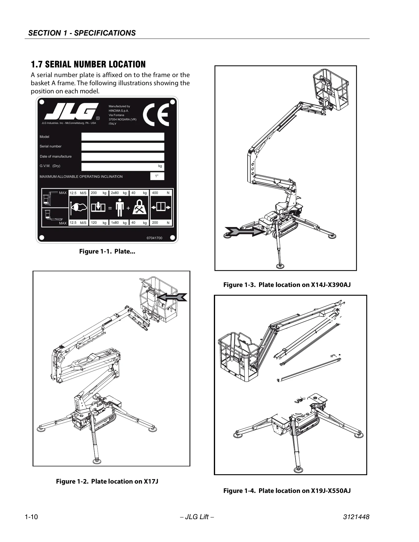
Machine specification material includes capacities, track specifications, ground-bearing pressures, engine data, reach and dimensional information, chassis data, function speeds and hydraulic pressure settings. This gives a technician useful reference values before diagnosis or adjustment begins. The manual also identifies serial-number plate locations for the covered machine families so the machine can be identified before parts or service information is applied.
Chapters Covered
- Introduction – Maintenance Safety Precautions
- General maintenance precautions, hydraulic system safety and maintenance safety requirements
- Section 1 – Specifications
- Capacities; tracks; Honda, Hatz and Perkins engine data; reach specifications; dimensional data; chassis specifications; function speeds; pressure settings; serial-number locations
- Section 2 – General
- Machine preparation, inspection and maintenance; pre-start, pre-delivery, frequent and annual inspections; preventative maintenance
- Service guidelines, cleanliness, component removal and installation, disassembly and reassembly, bearings, gaskets, bolt torque, hydraulic lines, electrical wiring and lubrication
- Hydraulic oil information and changing procedures; cylinder drift testing; pins and composite bearing repair guidelines; welding on JLG equipment
- Section 3 – Chassis & Turntable
- Rubber track tension, inspection and replacement; undercarriage rollers, track adjuster, wheel drive and motor replacement
- Cylinders and enlargement guide; drive gear motor information; Bonfiglioli MT700C077 track drive; Bonfiglioli 2T701C2K042002 track drive; Eaton drive hub; IMO swing drive
- Honda GX270-GX390 engine; Honda iGX440 engine; Hatz engine; Perkins engine; engine removal; electric motor replacement
- Section 4 – Boom & Platform
- Boom removal, main-boom disassembly, inspection, assembly and installation
- X23J-X700AJ boom disassembly; wire-rope and pulley inspection; rope tension adjustment; rotary actuator service
- Platform removal and installation; load-cell and footswitch removal and installation
- Section 5 – Hydraulics
- Hydraulic cylinder repair; hydraulic pump replacement; function pump
- Hydraulic component start-up procedures; pressure-setting procedure; hydraulic schematics
- Section 6 – JLG Control System
- Platform/remote control LCD display; CANBUS communications; module flashing codes; remote-control operation
- Calibration instructions; platform remote-control service; menu input; menu errors; ramps; currents; working hours and machine setup
- Joystick information and calibration; X17J radio remote-control serial-number configuration
Complete PDF Bookmark TreeComplete Bookmarks
The complete bookmarks in the “JLG X14J X17J X19J X23J X390AJ X550AJ X700AJ Service & Maintenance Manual 3121448 Rev C 2023” are as follows:
+Section 1. INTRODUCTION – MAINTENANCE SAFETY PRECAUTIONSp. 3
1.1 Generalp. 3A Hydraulic System Safetyp. 3B Maintenancep. 3+REVISON LOGp. 4
Original Issue June 6, 2012p. 4Revised June 29, 2018p. 4Revised February 3, 2023p. 4+Section 1. SPECIFICATIONSp. 9
1.1 Capacitiesp. 91.2 Tracksp. 10+1.3 Engine Datap. 11
HONDA ENGINE GX270 – GX390p. 11HATZ ENGINE 1B30 – 1B40p. 13+1.4 Specifications and Performance Datap. 14
Reach Specificationsp. 14+Dimensional Datap. 14
Chassisp. 151.5 FUNCTION SPEEDSp. 16+Machine Orientation When Doing Speed Testsp. 16
+Test Notesp. 16
1. Stop watch should be started with the function, not with the controller or switch.p. 162. All speed tests are run from ground with remote control connected on the basket.p. 163. Function speeds may vary due to cold, thick hydraulic oil. Test should be run with the oil temperature above 100° F (38° C).p. 161.6 PRESSURE SETTINGS – PSI (BAR)p. 171.7 SERIAL NUMBER LOCATIONp. 18+Section 2. GENERALp. 21
+2.1 Machine Preparation, Inspection, and Maintenancep. 21
Generalp. 21Preparation, Inspection, and Maintenancep. 21Pre-Start Inspectionp. 21Pre-Delivery Inspection and Frequent Inspectionp. 21Annual Machine Inspectionp. 21Preventative Maintenancep. 21+2.2 Service and Guidelinesp. 22
+Generalp. 22
The following information is provided to assist you in the use and application of servicing and maintenance procedures contained in this book.p. 22+Safety and Workmanshipp. 22
Your safety, and that of others, is the first consideration when engaging in the maintenance of equipment. Always be conscious of weight. Never attempt to move heavy parts without the aid of a mechanical device. Do not allow heavy objects to rest in …p. 22+Cleanlinessp. 22
1. The most important single item in preserving the long service life of a machine is to keep dirt and foreign materials out of the vital components. Precautions have been taken to safeguard against this. Shields, covers, seals, and filters are provi…p. 222. At any time when air, fuel, or oil lines are disconnected, clear adjacent areas as well as the openings and fittings themselves. As soon as a line or component is disconnected, cap or cover all openings to prevent entry of foreign matter.p. 223. Clean and inspect all parts during servicing or maintenance, and assure that all passages and openings are unobstructed. Cover all parts to keep them clean. Be sure all parts are clean before they are installed. New parts should remain in their co…p. 22+Components Removal and Installationp. 22
1. Use adjustable lifting devices, whenever possible, if mechanical assistance is required. All slings (chains, cables, etc.) should be parallel to each other and as near perpendicular as possible to top of part being lifted.p. 222. Should it be necessary to remove a component on an angle, keep in mind that the capacity of an eyebolt or similar bracket lessens, as the angle between the supporting structure and the component becomes less than 90 degrees.p. 223. If a part resists removal, check to see whether all nuts, bolts, cables, brackets, wiring, etc., have been removed and that no adjacent parts are interfering.p. 23+Component Disassembly and Reassemblyp. 23
When disassembling or reassembling a component, complete the procedural steps in sequence. Do not partially disassemble or assemble one part, then start on another. Always recheck your work to assure that nothing has been overlooked. Do not make any …p. 23+Pressure-Fit Partsp. 23
When assembling pressure-fit parts, use an anti-seize or molybdenum disulfide base compound to lubricate the mating surface.p. 23+Bearingsp. 23
1. When a bearing is removed, cover it to keep out dirt and abrasives. Clean bearings in nonflammable cleaning solvent and allow to drip dry. Compressed air can be used but do not spin the bearing.p. 232. Discard bearings if the races and balls (or rollers) are pitted, scored, or burned.p. 233. If bearing is found to be serviceable, apply a light coat of oil and wrap it in clean (waxed) paper. Do not unwrap reusable or new bearings until they are ready to install.p. 234. Lubricate new or used serviceable bearings before installation. When pressing a bearing into a retainer or bore, apply pressure to the outer race. If the bearing is to be installed on a shaft, apply pressure to the inner race.p. 23Gasketsp. 23+Bolt Usage and Torque Applicationp. 23
1. Use bolts of proper length. A bolt which is too long will bottom before the head is tight against its related part. If a bolt is too short, there will not be enough thread area to engage and hold the part properly. When replacing bolts, use only t…p. 232. Unless specific torque requirements are given within the text, standard torque values should be used on heat- treated bolts, studs, and steel nuts, in accordance with recommended shop practices. (See Torque Chart Section 1.)p. 23Hydraulic Lines and Electrical Wiringp. 23+Hydraulic Systemp. 23
1. Keep the system clean. If evidence of metal or rubber particles are found in the hydraulic system, drain and flush the entire system.p. 232. Disassemble and reassemble parts on clean work surface. Clean all metal parts with non-flammable cleaning solvent. Lubricate components, as required, to aid assembly.p. 23Lubricationp. 23Batteryp. 23Lubrication and Servicingp. 23+2.3 Lubrication and Informationp. 23
+Hydraulic Systemp. 23
1. The primary enemy of a hydraulic system is contamination. Contaminants enter the system by various means, e.g., using inadequate hydraulic oil, allowing moisture, grease, filings, sealing components, sand, etc., to enter when performing maintenanc…p. 232. The design and manufacturing tolerances of the component working parts are very close, therefore, even the smallest amount of dirt or foreign matter entering a system can cause wear or damage to the components and generally results in faulty opera…p. 233. Cloudy oils indicate a high moisture content which permits organic growth, resulting in oxidation or corrosion. If this condition occurs, the system must be drained, flushed, and refilled with clean oil.p. 244. It is not advisable to mix oils of different brands or types, as they may not contain the same required additives or be of comparable viscosities. Good grade mineral oils, with viscosities suited to the ambient temperatures in which the machine is…p. 24Hydraulic Oilp. 24+Changing Hydraulic Oilp. 24
1. Filter elements must be changed after the first 50 hours of operation and every 300 hours (unless specified otherwise) thereafter. If it is necessary to change the oil, use only those oils meeting or exceeding the specifications appearing in this …p. 242. Use every precaution to keep the hydraulic oil clean. If the oil must be poured from the original container into another, be sure to clean all possible contaminants from the service container. Always clean the mesh element of the filter and replac…p. 243. While the unit is shut down, a good preventive maintenance measure is to make a thorough inspection of all hydraulic components, lines, fittings, etc., as well as a functional check of each system, before placing the machine back in service.p. 24+Lubrication Specificationsp. 24
Specified lubricants, as recommended by the component manufacturers, are always the best choice, however, multi-purpose greases usually have the qualities which meet a variety of single purpose grease requirements. Should any question arise, regardin…p. 24+2.4 Cylinder Drift Testp. 24
Maximum acceptable cylinder drift is to be measured using the following methods.p. 24Cylinder Driftp. 24+2.5 Pins and Composite Bearing Repair Guidelinesp. 25
+1. Pinned joints should be disassembled and inspected if the following occurs:p. 25
a. Excessive sloppiness in joints.p. 25b. Noise originating from the joint during operation.p. 25+2. Filament wound bearings should be replaced if any of the following is observed:p. 25
a. Frayed or separated fibers on the liner surface.p. 25b. Cracked or damaged liner backing.p. 25c. Bearings that have moved or spun in their housing.p. 25d. Debris embedded in liner surface.p. 25+3. Pins should be replaced if any of the following is observed (pin should be properly cleaned prior to inspection):p. 25
a. Detectable wear in the bearing area.p. 25b. Flaking, pealing, scoring, or scratches on the pin surface.p. 25c. Rusting of the pin in the bearing area.p. 25+4. Re-assembly of pinned joints using filament wound bearings.p. 25
a. Housing should be blown out to remove all dirt and debris…bearings and bearing housings must be free of all contamination.p. 25b. Bearing / pins should be cleaned with a solvent to remove all grease and oil…filament wound bearing are a dry joint and should not be lubricated unless otherwise instructed (i.e. sheave pins).p. 25c. Pins should be inspected to ensure it is free of burrs, nicks, and scratches which would damage the bearing during installation and operation.p. 25+2.6 Welding on JLG Equipmentp. 25
Do the Following When Welding on JLG Equipmentp. 25Do NOT Do the Following When Welding on JLG Equipmentp. 25+Section 3. CHASSIS & TURNTABLEp. 27
+3.1 RUBBER TRACK MAINTENANCEp. 27
Checking track tensionp. 27+Operations for loosening/tightening the trackp. 27
1. Remove the screws and take of adjustment access lid 3.p. 272. To loosen the track, slowly unscrew valve 1 in an anti-clockwise direction for no more than one turn. One turn of valve 1 is sufficient to loosen the track.p. 273. If the grease does not start to drain, turn the track slowly.p. 274. When correct track tension has been obtained, turn valve (1) in a clockwise direction and tighten it. Clean all traces of grease.p. 275. To tighten the track, connect a grease gun to greaser (2) and add grease until belt tension is within the specified values.p. 27+Checking The Rubber Tracksp. 28
+1. Breakage of the steel ropesp. 28
a. when stones or foreign bodies accumulate between the track and the under-carriage frame;p. 28b. when the track escapes from its guide;p. 28c. in the case of strong friction such as rapid direction changes.p. 28+2. Wear and breakage of the metal coresp. 28
a. incorrect contact between toothed wheel and track;p. 28b. breakage of internal rollers;p. 28c. functioning on sandy land.p. 28+3. Separation of the metal coresp. 28
a. The metal core acts as a type of adhesive of the rubber between the core itself and the steel ropes. Separation may be caused by excessive tension as breakage of the ropes for the following reasons:p. 28b. The metal cores have been wound by the worn toothed wheel as indicated in the figure. When this wear and abrasion is detected, the toothed wheel must be replaced as soon as possible.p. 28c. If it breaks, as stated in item 2, "Wear and breakage of the metal cores", the track must be replaced because this damage leads to a complete loss of functions.p. 28+4. Abrasion and fatigue cracksp. 28
a. The cracks at the base of the carved profile occur due to bending fatigue of the rubber caused by the toothed wheel and the track- tensioning wheel.p. 28b. The cracks and bends on the edge of the rubber are due to manoeuvres with the track in presence of cement kerbs and edges.p. 28c. The cracks and abrasions in the rubber on the tracks of the roller guide originate from fatigue from the compression of the rubber by the weight of the wheel, together with functioning on sandy land, or repeated and abrupt changes of direction.p. 28d. Abrasion of the carved profiles may occur especially if slewing on concrete surfaces or on gravel or hard surfaces are carried out.p. 28e. The damage indicated in paragraphs a, b, and c above, must not be considered fatal for the track and, even if in presence of gradual and progressive damage, they allow the track to continue working. The development of the damage indicated in point…p. 285. Cracks due to external factorsp. 29+Replacing The Rubber Tracksp. 29
1. Stop the machine on solid, level land, lift it and support it in safe conditions, using the outriggers.p. 292. Remove the screws and take of adjustment access lid 3.p. 293. To loosen the track, slowly unscrew valve 1 in an anti-clockwise direction for no more than one turn. One turn of valve 1 is sufficient to loosen the track.p. 294. If the grease does not start to drain, turn the track slowly.p. 295. Insert three steel pipes (4) inside the track in the space between the rollers. Turn the driving wheel backwards (5) in a way that the steel pipes proceed with the track and engage on the track-tensioning wheel. Apply force (6) laterally to allow …p. 291. Check that the grease contained in the hydraulic cylinder has been removed.p. 292. Engage the track links with the toothed wheel and position the other end of the track on the track-tensioning wheel.p. 293. Turn the driving wheel in reverse (7) pushing the track plate inside the frame (8).p. 294. Position the track using a steel pipe and turn the driving wheel again.p. 295. Ensure that the track links are correctly engaged in the toothed wheel and in the track-tensioning wheel.p. 296. Adjust track tension (see paragraph -Operations for loosening/tightening the track).p. 297. Rest the tracked under-carriage on the ground.p. 29Checking tightness of nuts and boltsp. 30+3.2 UNDERCARRIGE COMPONENTSp. 35
a. Stabilize the machine on level ground.p. 35b. Fully extend the undercarriage.p. 35c. Remove the tracks (see paragraph 3.1).p. 35d. Remove the key ignition, and a tag with warning do not start the machine.p. 35+Replacement roller lower wheel and tracks adjusterp. 35
1. Remove the nuts 2 on the lower roller.p. 352. Remove the lower roller 3.p. 353. Remove the front idler 5.p. 354. Remove the tracks adjuster 4.p. 35+Replacement wheel drive and Motorp. 35
1. Stabilize the machine on level ground.p. 352. Fully extend the undercarriage.p. 353. Remove the tracks (see paragraph 3.1).p. 354. Remove the key ignition, and a tag with warning do not start the machine.p. 355. Remove screws 6.p. 356. Remove the sprocket 7.p. 357. To ensure a lifting system for the gearmotor 12 (30kg).p. 358. Disconnect and tag the hydraulic hoses from the gearmotor.p. 359. Remove the valve 10 to access all the screws 11 (on single speed versions only).p. 3510. Remove the screws 11.p. 3511. Remove the gearmotor 12.p. 35+3.3 CYLINDERS AND ENLARGEMENT GUIDEp. 37
1. Stabilize the machine on level surface.p. 372. Extend the undercarriage.p. 373. Engine and key off.p. 374. Remove the key ignition, and a tag with warning do not start the machine.p. 375. Open the hydraulic cap, and operate the function undercarriage extend/retract to discharge any residual pressure in the system.p. 376. Remove the cotter pin 1 .p. 377. Remove the pin 2.p. 378. Using a suitable lifting (minimum 200kg) to remove the track frame.p. 379. Remove screw and nut 3-6.p. 3710. Remove the pin 4.p. 3711. Disconnect, tag and plug the hydraulic hoses from the cylinder extension.p. 37+12. Remove the cylinder.p. 37
a. Unscrew the screws 7.p. 37b. Remove the stop slide guides 8.p. 37c. Remove the slide guides 9.p. 37d. Check the thickness of slide guides, if less than 3.5 mm, damage, with deep scratches or with deformation, replace its. Otherwise clean them and install by adding Grease GR MU EP1 before to install the track guides.p. 37e. Use medium strength Loctite (Loctite 52A43) on screws 7 and tightening torque of 10 Nm.p. 373.4 DRIVE GEAR MOTOR TABLEp. 38+3.5 TRACK DRIVE – Bonfiglioli (MT700C077)p. 39
Product Identificationp. 39+TECHNICAL INFORMATIONSp. 40
Product descriptionp. 40+INSTALLATION INFORMATIONSp. 43
+Installation procedurep. 43
1. Properly clean the product by removing packaging and all remains of protection padding.p. 432. Prepare the parts to be coupled using the installation drawing as a guide.p. 43+MOUNTING THE proDUCT TO THE MACHINEp. 43
1. Move the gearmotor in the mounting area applying lifting methods.p. 432. Install the motor gearbox connecting it to the machine frame and to the sprocket using all screws as the thread holes on to the flanges. Lock the screws with the tightening torque shown in the following scheme.p. 431. Make sure that the entire hydraulic system meets the cleaning standard as given in level 9 according NAS 1638 or 18/15 ISO/DIS 4406.p. 432. Clean the surface to be connected on the hydraulic motor.p. 433. Pipe the hydraulic motor as shown below (for pipe sizes and dimensions refer to the installation drawing).p. 431. Rotate the gearbox housing, so that the plug (1) is on the top of the cover.p. 452. Unscrew the two plugs (1-2) and fill from the upper hole until the oil flows out from the hole (2).p. 453. Tighten the oil plugs (1-2) and let the gearbox run. After a few minutes, stop and check the oil level.If necessary, refill.p. 451. Bleed air from every part of the hydraulic circuit and add oil in the tank if necessary.p. 462. Start the gearmotor at a low speed and gradually increase it after having verified that it is functioning correctly without any noises or vibrations.p. 461. Make sure that the speed and direction of rotation are correct.p. 462. Make sure that the functioning is regular and without any excessive noises and vibrations.p. 463. Make sure that the oil temperature does not exceed 60°C.p. 461. Check that there are no oil leakages. If present, proceed to remove them.p. 462. Check that there are no other problems in general.p. 46+MAINTENANCE INFORMATIONSp. 46
PERIODIC MAINTENANCEp. 46+changing the lubricating oilp. 46
1. Place a large enough container (about 1 litre) under the oil drain plug.p. 462. Unscrew the plug (2).p. 463. Unscrew the oil drain plug (1) and allow the oil to drain. To facilitate the draining operation, it is better to work with hot oil.p. 464. Wait a few minutes until all the oil is drained and than proceed to screw on drain plugs (1-2).p. 465. Proceed with the oil fill-up following the procedures given.p. 46troubleshootingp. 47+MOTORGEARBOX DISASSEMBLYp. 48
1. Cutting off all the hydraulic system connections on the gearmotor to avoid the introduction of any foreign bodies in the circuit and the gearmotor.p. 482. Making sure that the coupling surfaces are not damaged.p. 483. Following the handling so as to be sure that there are no risks for human safety and to guarantee the reliability of the gearmotor.p. 484. Making available a work area that is in line with work and health safety in the workplace guidelines.p. 48+DISASSEMBLING METHODp. 53
+Evaluation of the pieces to be replacedp. 63
1. Accurately remove dirt, and in particular properly clean the seals, bearings and locking rings seating.p. 632. Lubricate the parts before connecting them.p. 633. In the case of damaged gears, for example a planetary, do not proceed to replace the individual gear but the entire reduction assembly.p. 634. When reassembling a part always replace all the seals involved.p. 635. Replace all the damages parts with originals spare parts and doing so follow all the steps given by the manufacturer in section 4.7.p. 631. Carefully clean the seats ("A" and "B") using, if necessary, metal brushes or solvent (surfaces in contact with or ("C") must be perfectly clean and dry).p. 732. Make sure that sealing surfaces "D" of metal rings "E" are free from scratches, dings or foreign substances; metal ring surfaces must be perfectly clean and dry.p. 733. Carefully clean the lapped surface "D" of metal rings "E" and remove dust or finger prints. Then lubricate them with a thin oil film, taking care not to oil the other components.p. 73+DISMANTLING AND DESTROYING THE PRODUCTp. 79
1. Remove the gearbox from the machine frame and let the lubricant oil flow.p. 792. Completely dismount the gearbox and remove all oil and grease from its parts.p. 793. Send all dangerous and/or polluted parts to the authorized demolishing centers whilst keeping in line with respective local rules and regulations.p. 79+3.6 TRACK DRIVE – Bonfiglioli (2T701C2K042002)p. 80
Product Identificationp. 80+TECHNICAL INFORMATIONSp. 81
Product descriptionp. 81+INSTALLATION INFORMATIONSp. 84
+Installation procedurep. 84
1. Properly clean the product by removing packaging and all remains of protection padding.p. 842. Prepare the parts to be coupled using the installation drawing as a guide.p. 84+Installation of the track drive on the machinep. 85
1. Ensure that the structure to which the gear unit is to be mounted is sufficiently robust and rigid to support its weight and operating stresses.p. 852. Check that the machine to which the gear unit is to be installed is switched and cannot be accidentally switched on again.p. 853. Make sure all mating surfaces are flat.p. 854. Make sure the shaft / shaft or shaft / bore are perfectly aligned for coupling.p. 855. Fit suitable guards to protect against the gear unit’s external moving parts.p. 856. We recommend applying a protective paste to all gear/motor mating surfaces and other parts such as Klüberpaste 46 MR 401 or Tecnolube WRL 115 or similar product, to ensure optimal coupling and protection against fretting corrosion.p. 857. Move the track drive in the mounting area applying lifting methods.p. 858. Clean the mating surfaces from oils or paint and fit the track drive on the machine frame (for the correct orientation refer to the installation drawing).p. 859. Apply LOCTITE 270 on the thread screws (A). Fix the gearmotor to the machine frame tightening the screws (A) by a torque wrench at a torque shown on the following table.p. 85+Sprocket fixing to the track drivep. 85
1. Clean the mating surfaces from oils or paint and assemble the sprocket to the gearmotor.p. 852. Apply LOCTITE 270 on the thread screws (B). Fix the sprocket to the gearmotor tightening the screws (B) by a torque wrench at a torque shown on the following table.p. 85+Hydraulic system connectionp. 86
1. Make sure that the entire hydraulic system meets the cleaning standard as given in level 9 according NAS 1638 or 22/18/15 ISO/DIS 4406.p. 862. Clean the surface to be connected on the hydraulic motor.p. 863. Pipe the hydraulic motor as shown below (for pipe sizes and dimensions refer to the installation drawing).p. 86Gearbox lubricationp. 87+Oil fillingp. 88
1. Check that the gearbox axis is horizontal. Rotate the gearbox housing until the plug (1) is on the top on the vertical axis of the end cover.p. 882. Unscrew the oil plugs (1-2).p. 883. Fill from the hole (1) until the lubricant flows out from the hole (2).p. 884. Screw the oil plugs (1-2).p. 885. Run the gearbox, after a few minutes, stop and check the oil level.p. 886. If necessary, refill with lubricant oil (for plug orientation, size and dimension refer to the installation drawing).p. 88Characteristics of the hydraulic systemp. 88+First start up and running inp. 89
1. Check the correctly lubrication of the unit.p. 892. Fill the motor housing with hydraulic oil from the drain port (T1) (see the following picture).p. 893. Bleed air from every part of the hydraulic circuit and add oil in the tank if necessary.p. 891. Start the gearmotor at a low speed and gradually increase it after having verified that it is functioning correctly without any noises or vibrations.p. 891. Check the correct revolution and direction of rotation.p. 892. Make sure that the functioning is regular and without any excessive noises and vibrations.p. 893. Make sure that the oil temperature does not exceed 85-90°C intermittent.p. 891. Check that there are no oil leakages. If present, proceed to remove them.p. 892. Check the level of lubricating oil in the gearmotor.p. 893. Check that there are no other problems in general.p. 89+MAINTENANCE INFORMATIONSp. 90
+Periodic Maintenancep. 90
The gearmotor only requires the scheduled maintenance procedures set out by the manufacturer (see table below).p. 90Good maintenance will ensure an on going functioning in time as well as maximum reliability.p. 90Should irregularities in function arise, it will be necessary to consult the troubleshooting checklist to find the most adequate solution.p. 90If unsuccessful, it may be necessary to disassemble partially or completely the motorgearbox.p. 90+Oil draining and replacementp. 91
1. Check that the gearbox axis is horizontal. Rotate the gearbox housing until the plug (1) is on the bottom of the vertical axis of the end cover.p. 912. Unscrew the plugs (1-2) and let the oil flow in a large enough container; in order to facilitate the draining must be oil still warm.p. 913. Wait a few minutes until all the oil is drained and then proceed to screw on the plugs (1-2).p. 914. Proceed with the oil fill-up following the procedures given.p. 91Trouble shootingsp. 92+Disassemblyp. 93
1. Cutting off all the hydraulic system connections on the gearmotor to avoid the introduction of any foreign bodies in the circuit and the gearmotor.p. 932. Making sure that the coupling surfaces are not damaged.p. 933. Following the handling so as to be sure that there are no risks for human safety and to guarantee the reliability of the gearmotor.p. 934. Making available a work area that is in line with work and health safety in the workplace guidelines.p. 93+Gearbox disassemblyp. 96
Hydraulic motor disassemblyp. 99+Evaluation that pieces to replacep. 108
1. Accurately remove dirt, and in particular properly clean the seals, bearings and locking rings seating.p. 1082. Lubricate the parts before connecting them.p. 1083. In the case of damaged gears, for example a planetary, do not proceed to replace the individual gear but the entire reduction assembly.p. 1084. When reconnecting a part always replace all the seals involved.p. 1085. Replace all the damaged parts with original spare parts.p. 108+Reassembling Methotp. 109
Reassembly of the base platep. 113+Gearbox reassemblyp. 119
1. Carefully clean the seats (A and B) using, if necessary, metallic brushes or solvent (surfaces in contact with or (C) must be perfectly clean and dry).p. 1192. Make sure that sealing surfaces (D) of metal rings (E) are free from scratches, dinges or foreign substances; metallic ring surfaces must be perfectly clean and dry. We suggest to dip the metallic rings in volatile solvent or industrial degreasing…p. 1193. Carefully clean the lapped surface (D) of metal rings (E) and remove dust or fingerprints. Then lubrificate them with a thin oil film, taking care not to oil the other components.p. 119Final test and reinstallationp. 123+3.7 Drive Hub – eatonp. 124
+TR* series Orbit Motor Maintenance Manualp. 124
Introductionp. 124Tools required for disassembly and reassemblyp. 124+Disassemblyp. 124
Note: Don’t disassembly the followingp. 124Parts if not necessary.p. 124Reassemblyp. 126Trouble Shootingp. 131+3.8 Swing Drive (imo)p. 132
Technical data – Type platep. 132+Structure and functionp. 132
Brief descriptionp. 132Overviewp. 132+WD-L series (light series)p. 132
1. Connection for options: Potentiometer, permanent brake or front-end brakep. 1322. Worm shaftp. 1323. Lubricating nipplep. 1324. Ball slewing ringp. 1325. Option: Drive motorp. 1326. Bolted unions for the mounting structurep. 1327. Housingp. 1328. Lubricating nipplep. 132+Transporting unpacked slew drivesp. 133
1. Screw the 3 eye bolts into the 3 threads that are distributed uniformly on the circumference of the slew drive.p. 1332. Attach lifting gear to the eye bolts.p. 1333. Start the transport.p. 133Installation and commissioningp. 134Determination of flatness deviation, and perpendicularity deviation and deformation of the mounting structurep. 135Selecting the mounting elementsp. 139Tightening bolts with a torque wrenchp. 140+Positioning the slew drivep. 142
1. Determine the main load-carrying zone. The main load-carrying zone is that area of the slewing ring that is subject to the highest load, taking all aggressive forces and torques, and all occurring load cases into account.p. 1422. Arrange the hardness gap of the bearing ring charged with point load so that it is offset by 90° relative to the main load-carrying zone. The main load- carrying zone is in the main slewing range.p. 1423. Use a feeler gauge to check whether the support surface of the slew drive is completely supported by the mounting structure. If this is not the case, the support surface of the mounting structure must be reworked.p. 1424.p. 142+Bolting the slew drivep. 142
1. Lightly oil the bolt thread (not when using bolt locking devices with adhesive).p. 1422. Pretension the bolts, with washers if required, crosswise in 3 steps, 30%, 80%, and 100% of the tightening torque, or the hydraulically applied pretension force.p. 1423. In this process turn the unscrewed ring several times. Repeat the procedure for the bearing ring that has not yet been bolted.p. 142+Determining the tilting clearancep. 143
1. Upper mounting structurep. 1432. Tilting directionp. 1433. Main load-carrying zonep. 1434. Lower mounting structurep. 1431. Dial gaugep. 1432. Upper mounting structurep. 1433. Slew Drivep. 1444. Lower mounting structurep. 1441. Switch off the system and safeguard it from being turned on again.p. 1442. Permanently mark the measuring point in the main load direction on the housing and on the bearing ring.p. 1443. Attach the dial gauge as shown in Fig. 24.p. 1444. Apply defined tilt torque, at least 50% of max. operating load, in direction "A".p. 1445. Set dial gauge to zero.p. 1446. Apply defined tilt torque, at least 50% of max. operating load, in direction "B". The displayed measured value m1 corresponds to the existing tilting clearance and serves as the base value that will be used for comparison in later inspections.p. 1447. Log and document all measured values.p. 144Maintenance schedulep. 145Maintenance tasksp. 147+Inspecting the mounting boltsp. 147
1. Detached boltp. 147Checking the tilting clearancep. 147+Lubricating the slew drivep. 148
1. Fresh lubricantp. 1482. Lubricating nipple, bearing ringp. 1483. Lubricating ring housingp. 1481. In succession, press grease into all lubricating nipples while simultaneously turning the slew drive all the way through, until a continuous collar of grease forms under at least one seal.p. 1482. Ensure that old lubricant can escape without obstruction.p. 148+3.9 HONDA ENGINE GX270 – GX390p. 149
3.9.1 SPECIFICATIONSp. 149SERIAL NUMBER LOCATIONp. 149+ENGINE SPECIFICATIONSp. 150
SERVICE INFORMATIONp. 151TORQUE VALUESp. 151ENGINE TORQUE VALUESp. 151STANDARD TORQUE VALUESp. 151+HARNESS AND TUBE ROUTINGp. 152
COMBINATION SWITCH (CONTROL BOX) TYPEp. 152ALL TYPEp. 153WITH CHARGE COIL / LAMP COILp. 154MAINTENANCE SCHEDULEp. 155ENGINE OIL LEVEL CHECKp. 156ENGINE OIL CHANGEp. 156AIR CLEANER CHECK/CLEANING/ REPLACEMENTp. 157SEDIMENT CUP CLEANINGp. 158SPARK PLUG CHECK/ADJUSTMENTp. 159SPARK PLUG REPLACEMENTp. 159SPARK ARRESTER CLEANINGp. 160COMBUSTION CHAMBER CLEANINGp. 162FUEL TANK AND FILTER CLEANINGp. 163FUEL TUBE CHECKp. 163+TROUBLESHOOTINGp. 164
BEFORE TROUBLESHOOTINGp. 164TROUBLESHOOTINGHARDp. 165STARTINGp. 165ENGINE SPEED DOES NOT INCREASE OR STABILIZEp. 167ENGINE DOES NOT STOP WHEN COMBINATION/ ENGINE STOP SWITCH IS TURNED OFFp. 168ENGINE DOES NOT STOP WHEN ENGINE OIL LEVEL IS SLOWp. 169+COVERp. 170
COVERFAN COVER REMOVAL/INSTALLATIONp. 170+FUEL SYSTEMp. 171
FUEL FILLER CAP REMOVAL/INSTALLATIONp. 171FUEL FILTER REMOVAL/INSTALLATIONp. 171FUEL TANK REMOVAL/INSTALLATION (TYPE B)p. 172AIR CLEANER REMOVAL/INSTALLATIONp. 173CARBURETOR REMOVAL/INSTALLATIONp. 174CARBURETOR DISASSEMBLY/ASSEMBLYp. 175CHOKE CONTROL STAY DISASSEMBLY/ ASSEMBLYp. 176CHOKE DIAPHRAGM DISASSEMBLY/ASSEMBLYp. 177CARBURETOR BODY CLEANINGp. 178CARBURETOR INSPECTIONp. 179CHOKE DIAPHRAGM INSPECTIONp. 180+PILOT SCREW REPLACEMENTp. 180
Leave the pilot screw(1) and limiter cap(2) in place during carburetor cleaning. Remove only if necessary for carburetor repair.Removal of the limiter cap requires breaking the pilot screw. A new pilot screw and limiter cap must be installed.p. 180+GOVERNOR SYSTEMp. 181
+GOVERNOR SYSTEMGOVERNOR ARM/ CONTROL BASE ASSY. REMOVAL/ INSTALLATIONp. 181
1. Air cleanerp. 1812. Mufflerp. 1813. Fuel tankp. 1814. Tube clampp. 1811. Air cleanerp. 1822. Mufflerp. 1823. Fuel tankp. 1824. Tube clampp. 182CONTROL BASE ASSY. DISASSEMBLY/ ASSEMBLYp. 183MAXIMUM SPEED ADJUSTMENTp. 184+CHARGING SYSTEMp. 185
SYSTEM DIAGRAMp. 185BEFORE TROUBLESHOOTINGp. 186CHARGING SYSTEM TROUBLESHOOTINGp. 186COOLING FAN/FLYWHEEL REMOVAL/ INSTALLATIONREMOVALp. 187INSTALLATIONp. 188CHARGE / LAMP COIL (IF EQUIPPED) REMOVAL/INSTALLATIONp. 189CHARGE COIL INSPECTIONp. 190+IGNITION SYSTEMp. 191
IGNITION SYSTEMSYSTEM DIAGRAMp. 191IGNITION SYSTEM TROUBLESHOOTINGp. 192IGNITION COIL REMOVAL/INSTALLATIONp. 193IGNITION COIL INSTALLATIONp. 194SPARK PLUG CAP INSPECTIONp. 194IGNITION COIL INSPECTIONp. 195+STARTING SYSTEMp. 196
SYSTEM DIAGRAMp. 196STARTING SYSTEM TROUBLESHOOTINGp. 197RECOIL STARTER REMOVAL/INSTALLATIONp. 198RECOIL STARTER DISASSEMBLYp. 199RECOIL STARTER ASSEMBLYp. 200RECOIL STARTER INSPECTIONp. 202STARTER MOTOR REMOVAL/INSTALLATIONp. 203STARTER MOTOR DISASSEMBLY/ASSEMBLYp. 204BRUSH HOLDER INSTALLATIONp. 205INSPECTIONp. 205PERFORMANCE TESTp. 205STARTER SOLENOIDp. 205BRUSH LENGTHp. 205BRUSH CONTINUITY CHECKp. 206ARMATURE MICA DEPTHp. 206ARMATURE CONTINUITY CHECK – COMMUTATOR TO SHAFTp. 206ARMATURE CONTINUITY CHECK – COMMUTATOR SEGMENTSp. 206OVERRUNNING CLUTCHp. 207+STARTER SOLENOID WIREp. 207
Check the starter solenoid wire for continuity.p. 207+OTHER ELECTRICALp. 208
COMPONENT LOCATIONp. 208CONTROL BOX REMOVAL/INSTALLATIONp. 209CONTROL BOX DISASSEMBLY/ASSEMBLYp. 210OIL LEVEL SWITCH INSPECTIONp. 211ENGINE STOP SWITCH INSPECTIONp. 211COMBINATION SWITCH INSPECTIONp. 211SILICON RECTIFIER INSPECTIONp. 212CIRCUIT PROTECTOR INSPECTIONp. 212FUSE INSPECTIONp. 212REGULATOR/RECTIFIER INSPECTIONp. 213+MUFFLERp. 214
REMOVAL/INSTALLATIONp. 214SOLID PROTECTOR TYPEp. 214+CYLINDER HEAD/VALVESp. 215
+CYLINDER HEAD/VALVES INSPECTIONp. 215
CYLINDER COMPRESSION CHECKp. 215CRANKCASE COVER REMOVAL/ INSTALLATIONp. 216+WIRING DIAGRAMSp. 217
WIRING DIAGRAMSHOW TO READ A WIRING DIAGRAM & RELATED INFORMATIONp. 218+HOW TO READ CONNECTOR DRAWINGSp. 218
Connector drawings show the terminal arrangement, terminal No., number of pins, and the shape of terminal (male or female).p. 218HOW TO READ WIRING DIAGRAMp. 21910A / 18A CHARGE COIL TYPEp. 220+QUICK TROUBLESHOOTINGp. 221
HONDA GX270 – GX390p. 221+3.10 HONDA ENGINE iGX440p. 222
+SERIAL NUMBER LOCATIONp. 222
The engine serial number is stamped on the cylinder barrel. Refer to this when ordering parts or making technical inquiries.p. 222dimensions and weightp. 223enginep. 223WIRING DIAGRAMSp. 224+TROUBLESHOOTINGp. 225
+Self-diagnosis as indicated by the LEDp. 225
When the battery is disconnected, self-diagnosis with the LED is not possible.p. 225COILS AND IGNITION SWITCHES CHECKp. 237+spark testp. 239
1. Loosen the carburetor drain screw to drain the carburetor througly.p. 2392. Remove the spark plug cap from the spark plug.p. 2393. Remove the spark plug from the cylinder.p. 2394. Crank the engine several times to expel unburnt gas.p. 2395. Attach the spark plug cap to the spark plug.p. 2396. Ground negative (-) electrode (i. e. threaded part) of the spark plug against the cylinder side head cover bolt.p. 239+CYLINDER COMPRESSION CHECKp. 240
1. Remove the spark plug and spark plug.p. 2402. Turn the throttle control to the HIGH position.p. 2403. With recoil starter type:p. 240HARNESS ROUTINGp. 241TUBE ROUTINGp. 244+MAINTENANCEp. 245
MAINTENANCE SCHEDULEp. 245+ENGINE OILp. 246
Oil level check:p. 2461. Place the engine on a level surface.p. 2462. Turn the oil filler cap counterclockwise 90 degrees to unlock the cap and remove the oil level gauge from the oil filler neck. Wipe the oil level gauge clean.p. 2463. Insert the oil level gauge without screwing it into the oil filler neck. Remove the oil filler cap and check the oil level shown on the oil level gauge.p. 2464. If the oil level is near or below the lower level mark on the oil level gauge, fill with the recommended oil to the upper level mark.p. 2461. Check the engine on a level surface and remove the oil filler cap.p. 2472. Remove the oil drain bolt and sealing washer. and drain the oil into a suitable container.p. 2473. Tighten the oil drain bolt and a new sealing washer to the specified torque.p. 2474. Refill with the commended oil.p. 2471. Check the oil level and, if the oil level is near or below the lower limit mark on the oil level gauge, fill with the recommended oil to the upper level mark.p. 2472. Install the oil filler cap.p. 247+AIR CLEANERp. 247
1. Remove the air cleaner cover nut and air cleaner cover.p. 2472. Remove the wing nut, air cleaner elements (paper element and foam element) and air cleaner elbow packing, and separate them. Carefully check both elements for hole, or tear: and replace if damaged. Check the air cleaner claw packing for deteriorat…p. 2473. Foam element: Clean the element in warm soapy water, rinse and allow to dry thoroughly, or clean with a Nigh flash point solvent and allow to dry thoroughly. Dip the element in clear engine oil and squeeze out all the excess oil. Excess oil will r…p. 2474. Paper element: Tap the element lightly several times on a hard surface to remove excess dirt or blow compressed air lightly 207 kPa (2.1 kgf/cm2, 30 psi) or less) through the falter from the inside out. Never try to brush the dirt off; brushing wi…p. 2485. Wipe dirt from the inside of the air cleaner elbow and all cleaner cover, using a rag. Be careful to prevent dirt frond entering the air duct that leads to the carburetor.p. 2486. Install the foam element to the paper element. Install the air cleaner elbow packing and air cleaner ale' mints, and tighten the wing nut securely.p. 248+SPARK PLUGp. 248
1. Remove the spark plug cap and remove the spark plug using spark plug wrench.p. 2482. Visually inspect the spark plug. Discard the plug if the insulator is cracked of chipped.p. 2483. Remove carbon and other deposits with a plus cleaner or stiff wire brush. Check the sealing washer for damage.p. 2481. Measure the plug gag with a wire-type feeler gauge. If the measurement is outside the specification, adjust by bending the side electrode.p. 2481. Install the spark plug fingerings to beat the washer, and then tighten with a plug wrench. If reinstalling the used spark plug, tighten 1/8-1/4 turf after the spark plug seats. If installing a new spark plug, tighten 1/2 turn after the spark plug …p. 2492. Install the spark plug cap securely.p. 249+SPARK ARRESTERp. 249
1. Remove the spark arrester from the muffler.p. 2492. Clean the carbon deposits. from the spark arrester screed with a brush.p. 2493. Check the spark arrester screen for damage. If the gnarl arrester is damaged, replace it.p. 2494. Rainfall the spark arrester to the muffler.p. 249+VALVE CLEARANCEp. 250
1. Remove the cylinder head cover.p. 2502. With recoil starter type:p. 2503. Insert a feeler gauge between the rocker arm and valve to measure valve clearance.p. 250+1. If adjustment is necessary proceed is follows:p. 251
a. Hold the tappet adjusting screw using the special too and loosen the tappet adjusted screw lock nut.p. 251b. Turn the tappet adjusting screw to obtain the specifier clearance.p. 251c. Heighten the tappet adjusting screw lock nut while holding the rocker arm pivot.p. 2512. Install the cylinder head cover.p. 251+FUEL TANKp. 251
+1. Drain the fuel from the fuel tank into a suitable container.p. 251
a. Turn the fuel valve lever to the OFF position.p. 251b. Loosen the drain screw of the carburetor end drain tie fuel trio a suitable container.p. 2512. Remove the fuel tank, tank stay and auto fuel valve and disconnect the fuel tube from the auto feel valve.p. 2513. Disconnect the fuel lube end remove the fuel filter and oaring from the fuel lank. Wash the fuel filter in nonflammable or high flash point solvent. Inspect the fuel filter screen to be sure it is undamaged.p. 2514. Clean the fuel lank with nonflammable or high flash point solvent and allow to dry thoroughly.p. 2515. Install the fuel filter, O-ring, fuel valve, fuel tube and fuel tank cap. Connect the fuel tube to the fuel valve and install the fuel tank.p. 2516. After reassembly check for fuel leaks.p. 251FUEL TUBEp. 252+FUEL STRAINER CUPp. 252
1. Remove the fuel strainerp. 2522. Remove the fuel cup filter and clean it.p. 2523. Install the fuel cup filter and tighten the fuel strainer cup to the specified torque.p. 252+AIR CLEANERp. 253
REMOVAL/INSTALLATIONp. 253+MUFFLERp. 254
+REMOVAL/INSTALLATIONp. 254
1. Remove the air cleaner.p. 254+EXHAUST PIPE/MUFFLER PROTECTORp. 255
1. Attach a new muffler basket and exhaust pipe to the cylinder head.p. 2552. Move the exhaust pipe all the way to the fuel tank side and tighten the 8 mm flange nuts.p. 2553. Attach a new muffler gasket B and muffler to the exhaust pipe. Tighten the I x 14 mm CT bolt on the muller stay.p. 2554. Tighten the 8 mm flange nuts to install the muffler on the exhaust pipe.p. 2555. Put the muffler protector on the muffler and then loosely tighten the bolts in the numbered sequence as shown.p. 2556. Align the center of the muffler' protector exhaust slot wit) the reenter of. the spark arrester, and tighten the 6 x 14 mm CT bolt under the echoed! slot securely.p. 2557. Keep some clearance between the exhaust slot and the spark arrester, and tighten the other three bolts securely.p. 255+CARBURETORp. 256
+REMOVAL/INSTALLATIONp. 256
1. Remove the air cleaner.p. 256FUEL CUT SOLENOIDp. 259+FUEL TANKp. 260
+removal/installationp. 260
1. Remove the electric parts cover.p. 2602. Disconnect the fuel tube from the carburetor.p. 260DISASSEMBLY/REASSEMBLYp. 261TUBE CLIPp. 262+RECOIL STARTERp. 263
REMOVAL/INSTALLATIONp. 263+Reassemblyp. 264
1. Insert the starter rope end into the. starter reel and tie the rope as shown.p. 2642. Wind the rope onto the reel counterclockwise and hook the starter rope into the cutout of the starter reel.p. 2643. Wind the starter spring and install it to the starter reel by aligning the outer hook to the groove of the reel.p. 2644. Apply grease to the spring hook and boss of the starter case. Align the spring inner hook to the case claw on the case by turning the reel counterclockwise.p. 2645. Install the ratchet spring and ratchet as shown.p. 2646. Turn the reel three full turns counterclockwise to presoak the starter spring.p. 2657. Pass the rope through the starter case hole and started grip and knot the end of the rope as shown.p. 2658. Check the operation of tile ratchet by pulling the started rope out several times.p. 265+CONTROL PANELp. 266
REMOVAL/INSTALLATIONp. 266DISASSEMBLY/REASSEMBLYp. 267INSPECTIONp. 268+combination switchp. 268
Check continuity between the terminals at each switch position.p. 268+ENGINE STOP SWITCHp. 268
Check continuity between the terminals at each switch position.p. 268RECTIFIER/REGULATOR RECTIFIERp. 269+FUSEp. 269
1. Check for. a blown fuse; replace if necessary.p. 269+2. If the replaced fuse blows out, check the following.p. 269
a. Check the combination switch.p. 269b. Check the wire harness connecting the combination switch and ECM (Bl/Y) for open or short circuit.p. 269c. Check the rectifier or regulator rectifier.p. 269d. Check the combination switch.p. 269e. Check the wire harness connecting the combination swatch and ECM (BI/Y) for open or short circuit.p. 269+FAN COVER / FLYWHEELp. 270
1. Remove the air cleaner and electric parts cover.p. 2702. Remove the recoil starter or fan cover protector.p. 2703. Remove the control panel.p. 2704. Remove the pulser coil.p. 270FLYWHEELp. 271+REMOVALp. 271
1. Hold the flywheel with a commercially available strap wrench, and remove the 16 mm special nut.p. 2712. Remove the starter pulley and cooping fan.p. 2713. Remove the flywheel with a commercially available flywheel puller as shown.p. 271+INSTALLATIONp. 271
1. Clean the tapered part of dirt oil, grease and other foreign material before installation. Be sure there are no metal parts. or other foreign material on the magnet part of the flywheel.p. 2712. Set the woodruff key in the key groove of the crankshaft securely.p. 2713. Install the flywheel to the crankshaft.p. 2714. Attach the cooling fan to the flywheel by aligning the cutout of the cooling fan with the projection of the flywheel. Attach the starter pulley by aligning the hole of the pulley with the projection at the center of the cooling fan.p. 2715. Apply a light coat of oil to the threads once the seating surface of the 16 mm special nut, and loosely tighten the nut.p. 2716. Hold the flywheel with a commercially available strep wrench, tighten the 16 mm special nut to tie specified torque.p. 271+ELECTRIC EQUIPMENTp. 272
COILSp. 272+REMOVAL/INSTALLATIONp. 272
7. Remove the air cleaner and electric party cover.p. 2728. Remove the carburetor.p. 2729. Remove the recoil sterner or fan cover protector.p. 27210. Remove the control panel.p. 27211. R e m o v e t h e f a n c o v e r a n d fl y w h e e l.p. 272COINSp. 273+INSPECTIONp. 274
1. Remove the terminal cover from the connector using a flat-tip screwdriver.p. 2742. Measure the resistance between the BI and G terminals.p. 274+STARTER MOTORp. 275
1. Disconnect the starter motor terminal of the combination switch harness and starter motor battery terminal.p. 2752. Remove the harness bracket A.p. 2753. Remove the oil filler extension.p. 275DISASSEMBLY/REASSEMBLYp. 276+FRONT BRACKET/REAR BRACKET ASSEMBLYp. 277
1. Install the rear bracket lo the armature/yoke by aligning the brush terminal grommet with the cutout of the rear bracket.p. 2772. Attach the pinion drive lever to the starter solenoid. Set the pinion drive never to the overrunning clutch.p. 2773. Hold the pinion drive lever. starter solenoid and yoke together and install the front bracket. Tighten the through bolts to secure the front bracket and rear bracket.p. 277INSPECTIONp. 277STARTER SOLENOIDp. 277BRUSHp. 277ARMATUREp. 278+OVERRUNNING CLUTCHp. 279
1. Hold the pinion.gear.as shown and check that the gear turns clockwise and slides smoothly. If necessary, apply oil or replace the overrunning clutch.p. 2792. Check the pinion gear for wear or damage and replace if necessary.p. 2793. If the pinion ear is worn or damaged, the flywheel ring gear must be inspected.p. 279+Brush replacementp. 279
1. Cut off the brush lead at the point shown and remove the brush.p. 2792. Remove the remaining brush lead and deposited solder from the terminal.p. 2793. Hold a new brush in the same direction of the removed brush and put a new plate over the new brush and terminal and press it using a pair of pliers as shown.p. 2794. Solder the plate on the terminal.p. 279IGNITION COIL/FUEL CUT SOLENOID RECTIFIER/ENGINE TEMPERATURE SENSORp. 280INSPECTIONp. 281FUEL CUT SOLENOID RECTIFIERp. 281+ENGINE TEMPERATURE SENSORp. 281
1. Measure the air temperature before inspecting the engine temperature sensor. For the specified resistance value that should be shown at the air temperature, refer to the graph in the figure.p. 2812. Measure the resistance between the terminals of the engine temperature sensor, and make sure that it is consistent with the value shown in the graph.p. 281IGNITION COILp. 282+BREATHER VALVE/CRANKSHAFT/ BALANCER/PISTONp. 283
BREATHER VALVEp. 283+DISASSEMBLY/REASSEMBLYp. 283
1. Remove the air cleaner and electric parts cover.p. 2832. Remove the carburetor.p. 2833. Remove the recoil started or fan coyer protector.p. 2834. Remove the control' panel.p. 2835. Remove the fan cover and flywheel.p. 283+BREATHER COVER INSTALLATIONp. 284
1. Clean the old liquid gasket, oil and contamination from the breather cover/crankcase mating surface.p. 2842. Apply a bead (Ø1.0 – 1.5 mm (Ø 0.04-0.06 in)) of the liquid gasket (ThreeBond® 1207B) to the mating surface of the breather cover as shown.p. 2843. Install the breather cover to the crankcase.p. 284+OPERATIONp. 285
STR (Self Tuning Regulator) GOVERNORp. 285Functionsp. 285AUTO CHOKEp. 286+ENGINE PROTECTION/SELF DIAGNOSIS FUNCTIONp. 286
1. Since ECM controls the ignition timing, minute adjustments become possible, improving engine operation stability.p. 2862. Voltage loss at high-tension cords is minimal.p. 2863. Inspecting for broken connections at high-tension cords and adjusting air gap between the flywheel and ignition coil are not needed.p. 286AUTO FUEL VALVEp. 287LONG MAINTENANCE INTERVAL AIR CLEANER ELEMENTp. 288+QUICK TROUBLESHOOTINGp. 289
HONDA iGX440p. 289FIRST OPERATIONp. 290second OPERATION if problem is on enginep. 291+3.11 hatz enginep. 293
+TYPE: HATZ 1B30 – 1B40p. 293
+Description of the enginep. 294
1. Type platep. 2942. Cylinder head coverp. 2943. Exhaust silencerp. 2944. Exhaust mesh insertp. 2945. Oil pressure switchp. 2946. Starter motorp. 2947. Voltage regulatorp. 2948. Crankshaft – power take-offp. 2949. Oil drain plugp. 29410. Speed adjustment leverp. 29411. Oil filterp. 29412. Engine mountingsp. 29413. Ignition keyp. 29414. LED displayp. 29415. Intake opening for cooling and combustion airp. 29416. Oil filler pipe and dipstickp. 29417. Recoil starterp. 29418. Engine shutdown pinp. 29419. Dry-type air cleanerp. 29420. Lifting lugp. 29421. Fuel tank capp. 29422. Noise insulating hoodp. 294General notesp. 295+Type platep. 296
1. engine typep. 2962. code (only for special equipment)p. 2963. engine number (also stamped on crankcase)p. 2964. max. engine speedp. 296Operationp. 297Engine oilp. 297+Maintenancep. 303
Maintenance chartp. 303Checking the water trapp. 305Changing engine oilp. 306Checking and adjusting valve clearancesp. 306Cleaning cooling air areap. 308Checking screw connectionsp. 308Cleaning the exhaust mesh inletp. 308Maintenance every 500 operating hoursp. 309Model with external fuel filterp. 310Air cleaner maintenancep. 311Cleaning the filter cartridgep. 312Checking the filter cartridgep. 312+Maintenance every 1000 operating hoursp. 312
Cleaning the oil filterp. 312Malfunctions – causes and remediesp. 314Technical datap. 318+Engine oil circuitp. 319
1. Oil pressure switchp. 3192. Camshaft bearing, timing endp. 3193. Oil pumpp. 3194. Camshaft bearing, flywheel endp. 3195. Main and big-end bearings (crankshaft)p. 3196. Intake screenp. 3197. Oil mesh filterp. 3198. Gap between crankcase and cylinder liner (for heat dissipation)p. 319+Additional equipmentp. 320
Fuel tank 1B 30, 1B 40p. 320Dry-type air cleanerp. 322Starterp. 324Generatorp. 326Fittingsp. 328Gear ringp. 330+Basic engine equipmentp. 332
Adjusting lower idle speedp. 332Generator governor, speed controlp. 334Governor, engine speed adjustment with internal stopp. 336Recoil starterp. 338Air guidep. 340Breatherp. 342+Troubleshooting chart – electrical systemp. 344
Troubleshooting at the batteryp. 344Troubleshooting at the starting equipmentp. 347Code designations in circuit diagrams (DIN 40719)p. 350HATZ wiring designationsp. 351Circuit diagram for current and voltage measurementsp. 352+QUICK TROUBLESHOOTINGp. 359
HATZ 1B30—1B40p. 359+3.12 PERKINS ENGINEp. 360
TYPE: 402Dp. 360+Specificationsp. 361
Engine Identificationp. 361Serial Number Platep. 361+DISASSEMBLY AND ASSEMBLYp. 362
+Installation Procedurep. 362
1. Ensure that the fuel filter base is clean and free from damage. If necessary, replace the fuel filter base.p. 3622. If necessary, install new rubber olives (not shown) onto tube assemblies (3). Install tube assemblies (3) to fuel filter base (1). Ensure the correct orientation of the tube assemblies. Tighten the nuts to a torque of 9 N·m (80 lb in).p. 3623. Install washers (not shown) onto plugs (6). Install plugs (6) to fuel filter base (1). Tighten the plugs to a torque of 23 N·m (17 lb ft).p. 3624. Align fuel filter base (1) with the mounting bracket. Install fasteners (2). Tighten the fasteners to a torque of 50 N·m (37 lb ft).p. 3625. If necessary, install a new fuel filter element (7) to fuel filter base (1). Refer to Operation and Maintenance Manual, “Fuel System Filter – Replace”.p. 3626. Connect hoses (5) and tighten hose clamps (4).p. 3627. Turn the fuel supply to the ON position.p. 3628. Remove the air from the fuel system. Refer to Operation and Maintenance Manual, “Fuel System – Prime”.p. 362Fuel Filter Base – Remove and Installp. 362+Removal Procedurep. 362
1. Turn the fuel supply to the OFF position.p. 3632. Loosen hose clamps (3) and disconnect hoses (4).p. 3633. If necessary, remove fuel filter element (5). Refer to Operations and Maintenance Manual, “Fuel System Filter – Replace”.p. 3634. Remove bolt (1) and remove fuel filter base (2) from the mounting bracket.p. 363+Installation Procedurep. 363
1. Ensure that the fuel filter base is clean and free from damage. If necessary, replace the fuel filter base.p. 3632. Align fuel filter base (2) with the mounting bracket. Install bolt (1). Tighten the bolt to a torque of 25 N·m (18 lb ft).p. 3633. If necessary, install a new fuel filter element (6) to fuel filter base (2). Refer to Operation and Maintenance Manual, “Fuel System Filter – Replace”.p. 3634. Connect hoses (4) and tighten hose clamps (3).p. 3635. Turn the fuel supply to the ON position.p. 3636. Remove the air from the fuel system. Refer to Operation and Maintenance Manual, “Fuel System – Prime”.p. 363Fuel Transfer Pump – Remove and Installp. 364(Mechanical Fuel Transfer Pump)p. 364+Removal Procedurep. 364
1. Turn the fuel supply to the OFF position.p. 3642. Loosen the hose clamps and disconnect the hoses (not shown) from fuel transfer pump (1).p. 3643. Evenly loosen bolts (4) and remove fuel transfer pump (1) from the cylinder block.p. 3644. Remove O-ring seal (3) from fuel transfer pump (1).p. 364+Installation Procedurep. 364
1. Clean the mating surfaces of the cylinder block and flange (5) on the fuel transfer pump.p. 3642. Install a new O-ring seal (3) to fuel transfer pump (1).p. 3653. Lubricate the operating plunger of fuel transfer pump (1) with clean engine oil.p. 3654. Position fuel transfer pump (1) on the cylinder block. Ensure that the operating plunger is positioned correctly on the camshaft lobe. Install bolts (4). Tighten the bolts to a torque of 6 N·m (53 lb in).p. 3655. Connect the hoses (not shown) to fuel transfer pump (1). Tighten the hose clamps.p. 3656. Turn the fuel supply to the ON position.p. 3657. Prime the fuel system. Refer to Systems Operation, Testing and Adjusting, “Fuel System – Prime” for additional information.p. 365Fuel Transfer Pump – Remove and Installp. 365(Electrical Fuel Transfer Pump)p. 365+Removal Procedurep. 365
1. Turn the fuel supply to the OFF position.p. 3652. Turn the battery disconnect switch to the OFF position.p. 3653. Disconnect harness assembly (1).p. 3654. Loosen hose clamps (4) and (5). Disconnect hoses (6) and (7).p. 3655. Remove bolts (2) and remove electric transfer pump (3).p. 365+Installation Procedurep. 366
1. Ensure that the electric transfer pump is clean and free from damage. If necessary, replace the electric transfer pump.p. 3662. Position electric transfer pump (3) on the mounting and install bolts (2).p. 3663. Tighten bolts (2) to a torque of 9 N·m (79 lb in).p. 3664. Connect hoses (6) and (7). Tighten hose clamps (4) and (5).p. 3665. Connect harness assembly (1).p. 3666. Turn the fuel supply to the ON position.p. 3667. Turn the battery disconnect switch to the ON position.p. 3668. Remove the air from the fuel system. Refer to Operation and Maintenance Manual, “Fuel System – Prime”.p. 366Fuel Injection Lines – Remove and Installp. 366+Removal Procedurep. 366
1. Turn the fuel supply to the OFF position.p. 3662. Disconnect nuts (1) for fuel injection lines (2) from the fuel injectors.p. 3663. Disconnect nuts (1) for fuel injection lines (2) from the fuel injection pump.p. 3674. Remove fuel injection lines (2) from the engine as a unit.p. 3675. Use suitable caps in order to plug the open ports of the fuel injection pump immediately.p. 3671. Remove nuts (5) from fuel injectors (7).p. 3672. Remove fuel return line (3) and washers (6) from fuel injectors (7).p. 3673. Use suitable caps in order to plug the fuel injectors immediately.p. 367+Installation Procedurep. 367
1. Remove the caps from fuel injectors (7). Install new washers (6) and fuel return line (3) to fuel injectors (7).p. 3682. Install nuts (5) to fuel injectors (7).p. 3681. Tighten nuts (5) to a torque of 27 N·m (20 lb ft).p. 3682. Remove the caps from the outlet connections of the fuel injection pump. Install the fuel injection lines to the engine as a unit.p. 3683. Connect fuel injection lines (2) to fuel injectors (7). Tighten the union nuts (1) finger tight.p. 3684. Use Tooling (A) to tighten union nuts (1) at the fuel injection pump.p. 3681. Use Tooling (A) to tighten union nuts (1) at the fuel injections.p. 3681. Turn the fuel supply to the ON position.p. 3682. Prime the fuel system. Refer to Operation and Maintenance Manual, “Fuel System – Prime” for more information.p. 368Fuel Shutoff Solenoid – Remove and Installp. 368+Removal Procedurep. 368
1. Turn the battery disconnect switch to the OFF position.p. 3692. Disconnect electrical connection (3) from the harness assembly (not shown). Mark all connections for installation.p. 3693. Remove fuel shutoff solenoid (1) from the fuel injection pump housing by rotating the fuel shutoff solenoid in a counterclockwise direction.p. 3694. Remove sealing washer (2) from fuel shutoff solenoid (1).p. 369+Installation Procedurep. 369
1. Install sealing washer (2) to fuel shutoff solenoid (1).p. 3692. Install fuel shutoff solenoid (1) into the fuel injection pump housing by rotating the fuel shutoff solenoid in a clockwise direction. Tighten the fuel shutoff solenoid to a torque of 17 N·m (12 lb ft).p. 3693. Connect electrical connection (3) to the harness assembly (not shown).p. 3694. Turn the battery disconnect switch to the ON position.p. 369Fuel Injector – Remove and Installp. 369+Removal Procedurep. 369
a. Remove the fuel injection lines. Refer to Disassembly and Assembly, “Fuel Injection Lines – Remove and Install”.p. 3691. Use a deep socket to remove fuel injector (1) from the cylinder head.p. 3692. Remove seat washers (2) from the cylinder head.p. 3693. Cap all openings or plug all openings immediately.p. 369+Installation Procedurep. 370
1. Clean the bore for the fuel injector in the cylinder head. Ensure that no debris enters the cylinder. Clean the threads on the body of the fuel injector.p. 3702. Install new seat washers (2) into the bore for the fuel injector in the cylinder head.p. 3703. Apply a bead of Tooling (A) to the first two threads of the fuel injector that engage into the cylinder head. The bead should have a diameter of 2 mm (0.08 inch) and a length of 6 mm (0.25 inch).p. 3704. Install fuel injector (1) into the cylinder head. Use a deep socket to tighten the fuel injector to a torque of 64 N·m (47 lb ft).p. 370Exhaust Manifold – Remove and Installp. 370+Removal Procedurep. 370
a. If the engine is equipped with a turbocharger, remove the turbocharger. Refer to Disassembly and Assembly, “Turbocharger, Remove and Install”.p. 3701. Loosen nuts (5) and bolts (6).p. 3702. Remove nuts (5) and bolts (6).p. 3703. Remove exhaust manifold (4) from cylinder head (1). Note the orientation of the exhaust manifold for installation.p. 3704. Remove gasket (3) from cylinder head (1).p. 3705. If necessary, remove exhaust manifold studs (2) from cylinder head (1).p. 370+Installation Procedurep. 371
1. Ensure that the mating surfaces of the cylinder head and the exhaust manifold are clean and free from damage.p. 3712. If necessary, install exhaust manifold studs (2) to cylinder head (1).p. 3713. Install a new exhaust manifold gasket (3) to cylinder head (1).p. 3714. Align exhaust manifold (4) with studs (2) and install the exhaust manifold to cylinder head (1).p. 3715. Install nuts (5) and bolts (6) finger tight.p. 371+6. For 402D-05, 403D-07, 403D-11, 403D-15, 403D- 15T, 403D-17, and 404D-15 engines, tighten nuts (5) and bolts (6) to a torque of 10 N·m (89 lb in).p. 371
a. If the engine is equipped with a turbocharger, install the turbocharger. Refer to Disassembly and Assembly, “Turbocharger, Remove and Install”.p. 371Engine Oil Line – Remove and Installp. 371+Removal Procedurep. 371
1. Loosen nut (2) that attaches the clip on oil line (1) to the fuel injection pump.p. 3712. Remove banjo bolt (3) and remove washers (4) from the cylinder block.p. 3711. Remove banjo bolt (5) and remove washers (6) from the cylinder head.p. 3722. Remove oil line (1) from the engine.p. 372+Installation Procedurep. 372
1. Place oil line (1) on the engine. Ensure that the clip on the oil line is located below nut (2).p. 3722. Position banjo bolt (3) and new washers (4) onto oil line (1). Install the banjo bolt and oil line to the cylinder block finger tight.p. 3723. Position banjo bolt (5) and new washers (6) onto oil line (1). Install the banjo bolt and the oil line to the cylinder head finger tight.p. 3734. Tighten nut (2) that attaches the clip on oil line (1) to the fuel injection pump.p. 3735. Tighten banjo bolts (3) and (5) to a torque of 12 N·m (106 lb in).p. 373Engine Oil Cooler – Remove and Installp. 373+Removal Procedurep. 373
1. Drain the coolant from the cooling system into a suitable container. Refer to Operation and Maintenance Manual, “Cooling System Coolant – Drain” for the correct procedure.p. 3732. Drain the engine lubricating oil into a suitable container. Refer to Operation and Maintenance Manual, “Engine Oil and Filter – Change” for the correct procedure.p. 3733. Use Tooling (A) to remove oil filter element (5).p. 3734. Loosen hose clamps (2) and disconnect hoses (1). Note the positions of the coolant inlet and the coolant outlet for installation.p. 3735. Remove adapter (4) and remove oil cooler (3) from the cylinder block.p. 3736. Remove O-ring seal (6) from oil cooler (3).p. 373+Installation Procedurep. 374
1. Ensure that the oil cooler is clean and free from damage. Clean the mating surfaces of the cylinder block.p. 3742. Install a new O-ring seal (6) to oil cooler (3). Position oil cooler (3) on the cylinder block and install adapter (4). Tighten adapter (4) to a torque of 34 N·m (25 lb ft).p. 3743. Connect hoses (1) to the coolant inlet and the coolant outlet on oil cooler (3). Tighten hose clamps (2).p. 3744. Install a new oil filter element (5).p. 3745. Fill the cooling system to the correct level. Refer to Operation and Maintenance Manual, “Cooling System Coolant – Fill” for the correct procedure.p. 3746. Fill the engine oil pan to the correct level. Refer to Operation and Maintenance Manual, “Engine Oil Filter – Change” for the correct procedure.p. 374Engine Oil Relief Valve – Remove and Installp. 374+Removal Procedurep. 374
1. Remove engine oil relief valve (2) from the cylinder block.p. 3742. Remove O-ring seal (1) from engine oil relief valve (2).p. 374+Installation Procedurep. 375
1. Install a new O-ring seal (1) to engine oil relief valve (2).p. 3752. Lubricate engine oil relief valve (2) with clean engine oil.p. 3753. Install engine oil relief valve (2) into the cylinder block. Tighten the engine oil relief valve to a torque of 64 N·m (47 lb ft).p. 375Water Pump – Remove and Installp. 375+Removal Procedurep. 375
a. Remove the fan. Refer to Disassembly and Assembly, “Fan – Remove and Install”.p. 375b. Remove the alternator. Refer to Disassembly and Assembly, “Alternator – Remove and Install”.p. 3751. Drain the coolant from the cooling system into a suitable container for storage or disposal. Refer to Operation and Maintenance Manual, “Cooling System Coolant – Drain” for more information.p. 3752. Loosen the hose clamp and disconnect the hose (not shown) from the water pump inlet.p. 3751. Remove bolt (3) and remove adjusting link (2) for the alternator from water pump (1).p. 3762. Remove fasteners (7) and remove water pump (1).p. 3763. Remove joint (6) from the cylinder head.p. 376+Installation Procedurep. 376
1. Ensure that the mating surfaces of the water pump and the cylinder block are clean and free from damage. If the water pump has a spacer, ensure that the mating surfaces of the spacer are clean and free from damage.p. 3761. Install a new joint (6) to the cylinder head.p. 3762. Place water pump (1) in position and install fasteners (7). Tighten the fasteners finger tight.p. 3763. Position adjusting link (2) for the alternator on the water pump. Install bolt (3) finger tight.p. 3764. If the adjusting link for the alternator is secured by one bolt, tighten fasteners (7) to a torque of 10 N·m (89 lb in).p. 3775. Connect the hose (not shown) to the water pump inlet and tighten the hose clamp.p. 377+6. Fill the cooling system with coolant. Refer to Operation and Maintenance Manual, “Cooling System Coolant – Fill” for the correct procedure.p. 377
a. Install the alternator. Refer to Disassembly and Assembly, “Alternator – Remove and Install”.p. 377b. Install the fan. Refer to Disassembly and Assembly, “Fan – Remove and Install”.p. 377Water Temperature Regulator – Remove and Installp. 377+Removal Procedurep. 377
1. Drain the coolant from the cooling system into a suitable container for storage or disposal. Refer to Operation and Maintenance Manual, “Cooling System Coolant – Drain” for more information.p. 3772. Remove bolts (6) and nuts (5).p. 3773. Remove outlet connection (4).p. 3774. Remove joint (3).p. 3775. Remove water temperature regulator (2) and spring (1).p. 377+Installation Procedurep. 378
6. Inspect the water temperature regulator for wear, damage and correct operation. Refer to Systems Operation, Testing and Adjusting, “Water Temperature Regulator – Test” for more information. If necessary, replace the water temperature regulator.p. 3787. Ensure that the mating surfaces of the outlet connection and the cylinder head are clean and free from damage.p. 3788. Install spring (1) and water temperature regulator (2) to the cylinder head. Ensure that jiggle pin (7) on water temperature regulator (2) is in the vertically upward position.p. 3789. Install a new joint (3) to the cylinder head.p. 37810. Position outlet connection (4) onto the cylinder head. Install nut (5) and bolts (6) to outlet connection (4). Tighten the fasteners to a torque of 8 N·m (71 lb in).p. 37811. Fill the cooling system with coolant to the correct level. Refer to Operation and Maintenance Manual, “Cooling System Coolant – Fill” for more information.p. 378Crankshaft Pulley – Remove and Installp. 378+Removal Procedurep. 378
a. Remove the V-belt. Refer to Disassembly and Assembly, “V Belts Remove and Install” for more information.p. 3781. Loosen nut (3).p. 3782. Install Tooling (A) to crankshaft pulley (2). Use Tooling (A) in order to remove crankshaft pulley (2) from crankshaft (4). Remove Tooling (A).p. 3783. Remove nut (3).p. 3784. Remove pulley (2) from crankshaft (4).p. 3795. Remove woodruff key (1) from crankshaft (4).p. 379+Installation Procedurep. 379
1. Ensure that the following components are clean and free from damage: the taper of the crankshaft, the woodruff key, and the bore of the crankshaft pulley. Replace any components that are damaged. Ensure that the taper of the crankshaft and the bor…p. 3792. Install woodruff key (1) to crankshaft (4).p. 3793. Install crankshaft pulley (2) to crankshaft (4).p. 379+4. Lubricate nut (3) with clean engine oil and install the nut.p. 379
a. Install the V-belt to the engine. Refer to Disassembly and Assembly, “V Belts Remove and Install”.p. 379Crankshaft Front Seal – Remove and Installp. 379+Removal Procedurep. 379
a. Remove the crankshaft pulley. Refer to Disassembly and Assembly, “Crankshaft Pulley – Remove and Install”.p. 3791. Use a 4 mm (0.158 inch) drill in order to make three holes in crankshaft front seal (2).p. 3792. Use Tooling (A) to carefully remove crankshaft front seal (2). Alternate the position of Tooling (A) from one hole to another hole. This will allow you to evenly remove the crankshaft front seal from front housing (1).p. 380+Alternative Removal Procedurep. 380
a. Remove the crankshaft pulley. Refer to Disassembly and Assembly, “Crankshaft Pulley – Remove and Install”.p. 380b. Remove the front housing. Refer to Disassembly and Assembly, “Housing (Front) – Remove”.p. 3801. Use a suitable mandrel and a press in order to remove the oil seal from the front cover. Ensure that the front cover is supported in order to prevent damage to the cover while the oil seal is being removed.p. 380+Installation Procedurep. 380
1. Ensure that the bore in front housing (1) and the nose of the crankshaft are clean and free from damage.p. 3802. Lubricate the lip of a new crankshaft front seal (2) with clean engine oil.p. 3803. Position crankshaft front seal (2) in the bore of front housing (1).p. 3804. Use a suitable tool to install crankshaft front seal (2) to front housing (1).p. 380Housing (Front) – Removep. 381+Removal Procedurep. 381
a. Remove the fuel injection pump. Refer to Disassembly and Assembly, “Fuel Injection Pump – Remove”.p. 381b. Remove the crankshaft pulley. Refer to Disassembly and Assembly, “Crankshaft Pulley – Remove and Install”.p. 3811. If the engine is equipped with a turbocharger, disconnect the hose from connection (1).p. 3812. Remove nuts (4) and bolts (9).p. 3813. Remove cover (8) and O-ring seal (7).p. 3814. Remove fasteners (3). Identify the position of the different fasteners for installation.p. 3815. Carefully remove front housing (6) from plate (5). Ensure that pin (2) remains in the front housing.p. 3816. Remove the joint (not shown).p. 381Crankcase Breather – Remove and Install (Naturally Aspirated Engines)p. 382+Removal Procedurep. 382
1. Remove bolts (1) and remove the assembly of cover (2), spring (3) and diaphragm (4). Note the orientation of cover (2).p. 3822. Remove spring (3) and diaphragm (4) from cover (2).p. 382+3. If necessary, follow Steps 3.a through 3.c in order to remove the gauze for the breather.p. 382
a. Remove valve mechanism cover (7). Refer to Disassembly and Assembly, “Valve Mechanism Cover – Remove and Install” for the correct procedure.p. 382b. Remove screws (8) and carefully remove plate (9).p. 382c. Remove gauze (6) from valve mechanism cover (7).p. 382+Installation Procedurep. 383
1. Clean all parts and inspect all parts. Replace any parts that are worn or damaged. Ensure that the cavity for the breather in the valve mechanism cover is clean. Ensure that vent hole (5) and the vent hole in cover (2) are free from restriction.p. 383+2. If necessary, follow Steps 2.a through 2.d in order to install the gauze for the breather.p. 383
a. Install gauze (6) to valve mechanism cover (7).p. 383b. Position plate (9) on valve mechanism cover (7) and install screws (8).p. 383c. Tighten screws (8) to a torque of 1.5 N·m (13 lb in).p. 383d. Install valve mechanism cover (7). Refer to Disassembly and Assembly, “Valve Mechanism Cover – Remove and Install” for the correct procedure.p. 3833. Install diaphragm (4) and spring (3) to cover (2).p. 3834. Position the assembly of cover (2), spring (3) and diaphragm (4) onto valve mechanism cover (7).p. 3835. Install bolts (1). Use Tooling (A) in order to tighten bolts to a torque of 3 N·m (27 lb in).p. 383Valve Mechanism Cover – Remove and Installp. 384+Removal Procedurep. 384
1. Loosen the hose clamps and disconnect the hose (not shown) from connection (2).p. 3842. Remove nuts (5) and washers (6) from valve mechanism cover (7).p. 3843. Remove bolts (4) from valve mechanism cover (7).p. 3844. Remove valve mechanism cover (7) from base (8). Remove joint (9) from valve mechanism cover (7).p. 3845. If necessary, remove bolts (1) and remove connection (2) from valve mechanism cover (7). Remove gasket (2).p. 3846. If necessary, remove the crankcase breather. Refer to Disassembly and Assembly, “Crankcase Breather – Remove and Install” for more information.p. 384+Installation Procedurep. 385
1. Ensure that the valve mechanism cover is clean and free from damage. Clean the mating surface of base (8).p. 3852. If necessary, install the crankcase breather. Refer to Disassembly and Assembly, “Crankcase Breather – Remove and Install” for more information.p. 3853. Install a new joint (9) to valve mechanism cover (7).p. 3854. Position valve mechanism cover (7) onto housing (8) and install bolts (4) finger tight.p. 3855. Install new washers (6) and nuts (5) finger tight.p. 3856. For 402D-05, 403D-07, 403D-11 and 404D-15 engines, evenly tighten bolts (4) to a torque of 10 N·m (89 lb in). Tighten nuts (5) to a torque of 10 N·m (89 lb in).p. 3857. If necessary, position a new gasket (3) onto valve mechanism cover (7) and install connection (2). Install bolts (1) and tighten to a torque of 14 N·m (124 lb in).p. 3858. Connect the hose (not shown) to connection (2) and tighten the hose clamps.p. 385Coolant Temperature Switch – Remove and Installp. 386+Removal Procedurep. 386
1. Drain the coolant from the cooling system into a suitable container for storage or disposal. Refer to Operation and Maintenance Manual, “Cooling System Coolant – Drain” for more information.p. 3862. Disconnect the harness assembly (not shown) from coolant temperature switch (1).p. 3863. Remove coolant temperature switch (1) from water pump (2).p. 386+Installation Procedurep. 386
1. Inspect the coolant temperature switch for damage and correct operation. Refer to Systems Operation, Testing and Adjusting, “Coolant Temperature Switch – Test” for more information. If necessary, replace the coolant temperature switch.p. 3862. Install coolant temperature switch (1) to water pump (2). Use a deep socket to tighten the coolant temperature switch to a torque of 27 N·m (20 lb ft).p. 3863. Connect the harness assembly (not shown) to coolant temperature switch (1).p. 3864. Fill the cooling system with coolant to the correct level. Refer to Operation and Maintenance Manual, “Cooling System Coolant – Fill” for more information.p. 386Engine Oil Pressure Switch – Remove and Installp. 387+Removal Procedurep. 387
1. Disconnect the harness assembly (not shown) from engine oil pressure switch (1).p. 3872. If engine oil pressure switch (1) is located in the valve mechanism cover, remove the engine oil pressure switch from the valve mechanism cover.p. 387+3. If engine oil pressure switch (1) is located in the cylinder block follow Steps 3.a through 3.c in order to remove the engine oil pressure switch.p. 387
a. Remove engine oil pressure switch (1) and adapter (4) as an assembly from oil line (2).p. 387b. Remove washers (3).p. 387c. Remove engine oil pressure switch (1) from adapter (4).p. 387+Installation Procedurep. 387
1. If engine oil pressure switch (1) is located in the valve mechanism cover, install the engine oil pressure switch and tighten to a torque of 11 N·m (97 lb in).p. 388+2. If engine oil pressure switch (1) is located in the cylinder block follow Steps 2.a through 2.c in order to install the engine oil pressure switch.p. 388
a. Install engine oil pressure switch (1) to adapter (4). Tighten the engine oil pressure switch to a torque of 23 N·m (17 lb ft).p. 388b. Position new washers (3) onto oil line (2) and install the assembly of engine oil pressure switch (1) and adapter (4) to the cylinder block.p. 388c. Tighten adapter (4) to a torque of 11 N·m (97 lb in).p. 3883. Connect the harness assembly (not shown) to engine oil pressure switch (1).p. 388Glow Plugs – Remove and Installp. 388+Removal Procedurep. 388
1. Turn the battery disconnect switch to the OFF position.p. 3882. Remove nuts (1) and washers (2) from bus bar (3).p. 3883. Remove bus bar (3) from glow plugs (4).p. 3884. Remove glow plugs (4) from the cylinder head.p. 388+Installation Procedurep. 389
1. Ensure that the threads of the glow plugs are clean and free from damage. Replace any damaged glow plugs.p. 3892. Install glow plugs (4) into the cylinder head.p. 3893. Position bus bar (3) onto glow plugs (4).p. 3894. Install washers (2) and nuts (1) to glow plugs (4). Use Tooling (A) to tighten the nuts to a torque of 1.2 N·m (10.6 lb in).p. 3895. Turn the battery disconnect switch to the ON position.p. 389V-Belts – Remove and Installp. 389+Removal Procedurep. 389
1. If the engine is equipped with fan guards, remove the fan guards.p. 3892. Loosen bolts (1), (2) and (4).p. 3893. Push alternator (3) toward the engine and remove V- belt (5).p. 389+Installation Procedurep. 390
1. Check the condition of the V-belt. If the V-belt is worn or damaged, use a new V-belt for replacement.p. 3902. Install V-belt (5) in position on the engine.p. 3903. Slide alternator (3) away from the engine. Refer to Systems Operation, Testing and Adjusting, “Belt Tension Chart” for information on the correct belt tension. Tighten bolts (1), (2) and (4) to a torque of 25 N·m (18 lb ft).p. 3904. If the engine is equipped with fan guards, install the fan guards.p. 390Fan – Remove and Installp. 390+Removal Procedurep. 390
a. Remove the V-Belt. Refer to Disassembly and Assembly, “V-Belts – Remove and Install”.p. 3901. Remove bolts (1) and remove fan (2).p. 3902. Remove spacer (3) and pulley (4) from water pump (5).p. 390+Installation Procedurep. 391
1. Ensure that all components are clean and free from damage. Replace any components that are worn or damaged.p. 3912. Position pulley (4) and spacer (3) on water pump (5). Ensure that the bolt holes are aligned.p. 3913. Install fan (2).p. 391+4. Install bolts (1) and tighten to a torque of 11 N·m (97 lb in).p. 391
a. Install the V-Belt. Refer to Disassembly and Assembly, “V-Belts – Remove and Install”.p. 391Alternator – Remove and Install (14 Amp and 15 Amp Alternators)p. 391+Removal Procedurep. 391
a. Remove the V-Belt. Refer to Disassembly and Assembly, “V-Belts – Remove and Install”.p. 3911. Turn the battery disconnect switch to the OFF position.p. 3912. Make temporary identification marks on the connections of the harness assembly.p. 3913. Disconnect the harness assembly (not shown) from alternator (6).p. 3914. Remove bolt (1), washer (3) and nut (4) from alternator (6).p. 3915. Remove bolt (7) and remove alternator (6) from the engine.p. 3916. If necessary, remove bolts (5) and remove adjusting link (2).p. 391+Installation Procedurep. 392
1. If necessary, install adjusting link (2) and install bolts (5) finger tight.p. 3922. For engines that have an adjusting link that is secured by one bolt, leave bolt (5) loose.p. 3923. Position alternator (6) on the engine and install bolt (7) finger tight.p. 3924. Install bolt (1), washer (3) and nut (4) finger tight.p. 3925. Install the V-Belt. Refer to Disassembly and Assembly, “V-Belts – Remove and Install”.p. 3926. Connect the harness assembly (not shown) to the alternator.p. 3927. Turn the battery disconnect switch to the ON position.p. 392Electric Starting Motor – Remove and Installp. 392+Removal Procedurep. 392
1. Disconnect the battery.p. 3922. Make temporary identification marks on the harness assemblies that are connected to the electric starting motor.p. 3923. Disconnect the harness assemblies (not shown) from electric starting motor (2).p. 3924. Remove fasteners (1) that secure electric starting motor (2).p. 3925. Remove electric starting motor (2) from the engine.p. 392+Installation Procedurep. 393
1. Install electric starting motor (2) in position on the engine.p. 3932. Install fasteners (1) and tighten to a torque of 50 N·m (37 lb ft).p. 3933. Connect the harness assemblies (not shown) to electric starting motor (2).p. 3934. Connect the battery.p. 393+PERKINS RPM CONTROL SYSTEMp. 394
1. Slightly flared the 4 threaded holes of the servo command, cut one side of the fillets of vibration to about 5-6MM.p. 3942. Put a little 'of fat on the joint where she works and a M6 nut low.p. 3943. Mount it on the servo control and tighten until bottom.p. 3954. Cut to 10mm bolt for the throttle, tighten and tighten down with nut M6.p. 3955. Orientate the bracket with 2 screws + washer 5/ 16X3/4 flat. Removing one at a time to put the thread lock and pull.p. 3956. Mount the actuator and record it in line, check the operation with the help of a battery.p. 3957. Wires 2 on the actuator to a sheath L = 250 and a connector with 2-way super-seel door males. The red wire on connector (2) and black wire on connector (1).p. 395+QUICK TROUBLESHOOTINGp. 396
perkins 402.05p. 396+3.13 ENGINE removalp. 397
1. Stabilize and turn the machine on level surface at 90° (image 1).p. 3972. Remove the key ignition, and a tag with warning do not start the machine.p. 3973. Remove the cover 1.p. 3974. Disconnect, tag and isolate the wires from the engine.p. 3975. Unscrew the screws (13-5 image 2).p. 3976. Remove the engine (Kg 70), remove the joint (8-9 Image 2) .p. 3977. Remove the muffler (6 Image 2).p. 3978. Replace the engine and tighten the screws (13-5 Image 2) respectively with the copies of tightening of 22Nm and 25Nm.p. 3979. Connect the wires to the motor.p. 39710. Replace guard on motor (1) and test the machine.p. 397+3.14 CHANGING THE ELECTRIC MOTORp. 398
1. Stabilize and turn the machine on level ground at 90° (image 1).p. 3982. Before beginning the maintenance check that the machine is disconnected from the mains and unplug the ignition key.p. 3983. Remove casing (1).p. 3984. Open cover engine wiring Electrical (7) mark the position of the wires then disconnect and isolate it.p. 3985. Unscrew the screws (2-6).p. 3986. Remove the electrical motor and the joint (4-5).p. 3987. Install the electrical motor (40 kg), and connect the wires as shown in (image 3), screw the cover (7).p. 3988. Tighten the screws (2-6), respectively, with copies of torque of 40Nm and 22Nm.p. 3989. Inspect from the fan side, the direction of the electrical motor. If the electrical motor turning in CCW change the position of the connectors as on (image 4).p. 39810. Install cover (1) and test the machine.p. 398+Section 4. BOOM & PLATFORMp. 401
+4.1 BOOM MAINTENANCEp. 401
+Removal of the Boom Assemblyp. 401
+1. Remove the platform and platform support as follows:p. 401
a. Disconnect electrical cable from control console.p. 401b. Tag and disconnect the hydraulic lines running to the rotate cylinders. Cap the hydraulic lines and ports.p. 401c. Using an overhead crane or suitable lifting device, use nylon support straps to support the platform/support.p. 401a. Remove bolts and keeper pins that secures the retaining pins. Using a suitable brass drift and hammer, remove the retaining pins from the platform support.p. 401+1. Remove the boom from the turntable as follows:p. 401
a. Disconnect wiring harness from ground control harness connector.p. 401b. Tag and disconnect hydraulic lines from boom to control valve. Use a suitable container to retain any residual hydraulic fluid. Cap all hydraulic lines and ports.p. 401c. Using a suitable lifting equipment, adequately support boom weight along entire length.p. 401d. Remove the bolts and keeper pins securing the lift cylinder pivot pin. Using a suitable brass drift and hammer, remove the pivot pin from the lower boom.p. 401a. e. Remove hardware securing the level link pivot pin. Using a suitable brass drift and hammer, remove the pin from the level link and turntable.p. 402b. f. Remove hardware securing the lower boom pivot pin. Using a suitable brass drift and hammer, remove pin from the turntable.p. 402c. g. Using all applicable safety precautions, carefully lift boom assembly clear of turntable and lower to ground or suitable supported work surface.p. 402+Disassembly of the Main Boomp. 402
1. Loosen jam nuts on aft end of fly boom wear pad adjustment and loosen adjustments.p. 4022. Using a portable power source, attach hose to telescope cylinder port block. Using all applicable safety precautions, activate hydraulic system and extend cylinder to gain access to cylinder rod retaining pin. Shut down hydraulic system.p. 4023. Carefully disconnect hydraulic hose from retract port of cylinder. There will be initial weeping of hydraulic fluid which can be caught in a suitable container. After initial discharge, there should be no further leakage from the retract port.p. 4024. Remove hardware securing telescope cylinder to the fly boom section, then remove pin from fly.p. 4025. Remove hardware securing telescope cylinder to the base boom section.p. 4026. Using a suitable lifting device, remove telescope cylinder from boom sections.p. 4027. Using a piece of tape, mark the length of hoses and wires from front of fly boom and bottom of base boom for reassembly.p. 4028. Remove hardware securing the front wear pads on base boom section, remove wear pads.p. 4029. Remove hardware securing the powertrack to the aft end of the fly boom section.p. 40210. Using a suitable lifting device, remove fly boom from boom section.p. 40211. Remove hydraulic lines and electrical cables from powertrack.p. 40212. Remove hardware securing powertrack to the base boom section. Remove powertrack.p. 402+Inspectionp. 402
1. Inspect all boom pivot pins for wear, scoring or other damage, and for tapering or ovality. Replace pins as necessary.p. 4022. Inspect lift cylinder pins for wear, scoring or other damage, and for tapering or ovality. Ensure pin surfaces are protected prior to installation. Replace pins as necessary.p. 4023. Inspect telescope cylinder rod attach pin for wear, scoring or other damage. Replace pin as necessary.p. 4024. Inspect inner diameter of boom pivot bushings for scoring, distortion, wear or other damage. Replace bushings as necessary.p. 4025. Inspect wear pads for wear.p. 4026. Inspect all threaded components for damage such as stretching, thread deformation, or twisting. Replace as necessary.p. 4027. Inspect structural units of boom assembly for bending, cracking, separation of welds, or other damage. Replace boom sections as necessary.p. 402+Assembly of the Main Boomp. 402
1. Install power track to the attach point on the base boom section. Secure power track with the attaching hardware.p. 4022. Install hydraulic lines and electrical cables into the power track.p. 4023. Install wear pads to the aft end of the fly section.p. 4024. Using suitable lifting equipment, slide fly section into the base section until power track attach point aligns with holes in side of base section.p. 4025. Attach the power track to the aft end of fly boom section. Secure power track with the attaching hardware.p. 4026. Using suitable lifting equipment, slide fly boom section out to gain access to telescope cylinder attach pin hole.p. 4037. Measure the distance between the telescope cylinder port block attach point on base boom section and the attach point on fly boom section.p. 4038. Connect a suitable auxiliary hydraulic power source to the telescope cylinder port block.p. 4039. Extend the telescope cylinder the distance of the two attach points.p. 40310. Secure the sling and lifting device at the telescope cylinder’s approximate center of gravity, and lift the cylinder to the aft end of the boom assembly.p. 40311. Slowly slide the telescope cylinder into boom assembly, align rod end with attach point in fly section. Insert pin and secure with retaining ring.p. 40312. Slowly slide the telescope cylinder into boom assembly, align barrel end with attach point in fly section. Insert pin and secure with retaining ring.p. 40313. Install wear pads at front of base boom section. Adjust the wear pads to zero clearance.p. 40314. Adjust pads alternately side to side, so that fly boom section is centered in base boom section (lower wear pad with 1 mm gap).p. 40315. Turn the wear pad to dispose the groove on the head to insert the cotter.p. 40316. Disconnect auxiliary power source from telescope cylinder.p. 403+Installation of the Boom Assemblyp. 404
1. Using suitable lifting equipment, position boom assembly on turntable so that boom pivot holes in both boom and turntable are aligned.p. 4042. Install boom pivot pin, ensuring that location of the hole in pivot pin aligns with attach point on upright.p. 4043. Using all applicable safety precautions, operate lifting equipment in order to position boom lift cylinder and level link so that holes in cylinder rod end and level link are aligned with the one in the turntable. Insert cylinder pins.p. 4044. If necessary, gently tap pins into position with a soft headed mallet, ensuring that attach holes in pins are aligned with attach holes in boom structure. Secure with hardware.p. 4045. Connect all hosing and wiring.p. 4046. Install the platform to the boom assembly.p. 4047. Connect all hosing and wiring at platform control station.p. 4048. Using all safety precautions, operate machine systems and extend and retract boom for four or five cycles.p. 4049. Shut down machine systems and check for leakage.p. 404+4.2 Boom Disassembly X23J – X700AJp. 407
1. Extend the boom approximately 2 feet (0.6 m). This will enable access to the bolts that secure the cable mount block to the boom fly section.p. 4072. Remove hardware securing the telescope cylinder.p. 4073. Clamp both threaded ends of wire rope to prevent rotation. Note: Do not clamp on threads. Remove jam nuts and nuts which secure the wire rope adjustments to the bottom front of the base boom section.p. 4074. Using a M6 drive extension approximately 4 feet (1.2 m) long, remove the bolts and washers securing the cable mount block to the boom fly section.p. 4075. Remove the four bolts, shims, and attachment blocks that secure the telescope cylinder barrel to the boom mid section.p. 4076. Remove the four bolts, shims, and mounting blocks that secure the telescope cylinder rod to the boom base section.p. 4077. Using overhead cranes or other suitable lifting/supporting devices, carefully pull the telescope cylinder out from the back of the boom. At the same time, also pull the cable mount block out so the extension cables come out with the telescope cyli…p. 4081. Base boomp. 4092. Mid boomp. 4093. Fly boomp. 4094. Telescope cylinderp. 4095. Extend sheavep. 4096. Retract sheavep. 4097. Sheave blockp. 4098. Extend cablep. 4099. Retract cablep. 40910. Extend cable adjustmentp. 40911. Retract cable adjustmentp. 40912. Proximity switchp. 40913. Wear padp. 409+14. Wear padp. 409
a. Remove hardware from the wear pads; remove wear pads from cylinder.p. 410b. Remove hardware from the wire rope guard; remove guard from cylinder.p. 410c. Remove hardware from the sheave pin; remove pin and sheave from cylinder.p. 4101. 9. Remove hardware which secures the wear pads to the front of base boom section; remove wear pads from the top, sides and bottom of the base boom section.p. 4102. 10. Using an overhead crane or suitable lifting device, remove mid and fly boom sections from base section. Note: When removing mid and fly boom sections from base boom section, retract wire rope must be dragged along with boom sections.p. 4103. 11. Remove hardware which secures the wear pads to the rear end of mid boom section; remove the wear pads from the top, sides and bottom of the mid boom section.p. 4104. 12. Remove hardware which secures the sheave guards and sheave assemblies to mid boom section, remove sheave assemblies from mid boom section.p. 4105. 13. Remove hardware which secures the wear pads to the front of mid boom section; remove wear pads from the top, sides and bottom of the mid boom section.p. 4106. 14. Using an overhead crane or suitable lifting device, remove fly boom section from mid section. Note: When removing fly boom section from mid boom section, retract wire rope must be dragged along with fly boom section.p. 4107. 15. Remove hardware which secures the wear pads to the rear end of fly boom section; remove wear pads from the top, sides and bottom of the fly boom section.p. 4108. 16. When removing wire rope from fly boom section, push the cable into fly boom. Route wire rope back through holes in the side of the fly boom section.p. 410+4.3 Inspectionp. 411
+Checking wear and deformation of ropes and pulleysp. 411
1. Check that there are no broken threads on the surface of the rope, in the internal area or in correspondence with the cable socket.p. 4112. Check that there are no signs of corrosion on the rope.p. 4113. Check that there are no signs of kinking, crushing or deformations of any type on the rope.p. 4114. Check the condition of the fixing pins of the outlet pulley and extensions return.p. 4115. Check the wear of the pulley grooving using a profile comparator. As indicated in the figure it is necessary to check that the outline of the comparator corresponds with the base of the grooving.p. 4116. Check that there are no signs of ovalisation, wear or any other type of deformation on the pulleys.p. 411+Assemblyp. 411
1. Measure inside dimensions of the base and mid sections to determine the number of shims required for proper lift.p. 4112. Measure inside dimensions of the mid section to determine the number of shims required for proper lift.p. 4113. Install side, top and bottom wear pads to the rear end of fly section; shim evenly to the measurements of the inside of mid section.p. 4114. Install retract wire ropes into rear end of fly section, route wire ropes thru holes in side of fly boom section and pull into slot.p. 4115. Install side, top and bottom wear pads to the rear end of mid section.p. 4116. Slide fly boom section into the mid boom section. Adjust boom, if necessary, for a total of 1/16 inch (0.062) clearance.p. 4117. Install wear pads into the forward position of the mid boom section. Adjust boom, if necessary, for a total of 2/10 inch (0.50) clearance.p. 4118. Properly position the retraction wire rope sheaves assemblies at the rear end of the mid boom section; ensure all sheave-to-mounting block attachment holes align. Install the sheave pins and secure them with mounting hardware. Position retract wir…p. 4129. Install sheave guards to rear end of mid boom section and secure with mounting hardware.p. 41210. Slide mid boom section into the base boom section. Allow the retraction wire ropes to trail between the bottom surfaces of boom sections. Adjust boom, if necessary, for a total of 1/16 inch (0.062) clearance.p. 41211. Install wear pads into the forward position of the base boom section. Adjust boom, if necessary, for a total of 2/10 inch (0.20) clearance.p. 41212. Install sheave block to bottom of base boom section and adjust block so that retract wire ropes do not come into contact with boom surfaces.p. 41213. Install wire rope threaded ends thru attachment holes in the bottom of base boom section. Loosely install nuts and jam nuts onto the threaded ends of wire ropes.p. 41214. Pull the boom sections out to approximately where they were extended to for telescope cylinder removal.p. 41215. Install a new extend sheave on the end of the telescope cylinder.p. 41216. Route new extend cables around the telescope cylinder. Loosely fasten the threaded end of the cables to the rod end of the telescope cylinder with the adjusting nuts and lock nuts. Install the opposite end of the cables in the cable mount block.p. 41217. Use tape or tie straps to fasten the cables to the telescope cylinder assembly. It is important that the tape or straps be strong enough to hold the cable in place yet weak enough to break and fall away when the cables are adjusted.p. 41218. Using adequate lifting equipment, carefully push the telescope cylinder assembly and cables back into the boom.p. 41219. Apply Loctite #242 to the bolts and fasten the telescope cylinder rod to the boom base section with the bolts, shims, mounting blocks.p. 41220. Apply Loctite #242 to the bolts and fasten the telescope cylinder barrel to the boom mid section with the bolts, shims, mounting blocks.p. 41221. Using a 3/8 drive extension approximately 4 feet (1.2 m) long, install the bolts and washers securing the cable mount block to the boom fly section. Tape the bolts to the socket at the end of the extension to prevent it from coming out of the soc…p. 41222. Connect all the hydraulic lines to the cylinder as tagged during the removal procedure.p. 41323. Adjust the boom cables as outlined under Section 4.4, Ropes Tension Adjustment Procedure.p. 413+Installationp. 413
1. Using a suitable lifting device, position boom assembly on upright so that the pivot holes in both boom and upright are aligned.p. 4132. Install boom pivot pin, ensuring that location of hole in pin is aligned with attach point on upright.p. 4133. If necessary, gently tap pin into position with soft headed mallet. Secure pin mounting hardware.p. 4134. Connect all wiring to the ground control box.p. 4135. Connect all hydraulic lines running along side of boom assembly.p. 4136. Using all applicable safety precautions, operate lifting device in order to position boom lift cylinder so that holes in the cylinder rod end and boom structure are aligned. Insert the lift cylinder pin, ensuring that location of hole in pin is al…p. 4137. Align holes in boom structure with hole in master cylinder. Insert the master cylinder pin, ensuring that location of hole in pin is aligned with attach point on boom.p. 4138. Adjust retract and extend cables to the proper torque. Refer to Section 4.4, Ropes Tension Adjustment Procedure.p. 4139. Using all applicable safety precautions, operate machine systems and raise and extend boom fully, noting the performance of the extension cycle.p. 41310. Retract and lower boom, noting the performance of the retraction cycle.p. 413+4.4 Wire Rope and Pulleysp. 414
1. Raise boom approximately horizontal.p. 4142. Extend and retract all boom sections.p. 4143. Check for delayed movement in any section which indicates loose wire ropes.p. 414+Inspectionp. 414
1. Inspect ropes for broken wires, particularly valley wire breaks and breaks at end terminations.p. 4142. Inspect wire ropes for corrosion.p. 4143. Inspect wire ropes for kinks or abuse.p. 4144. Inspect sheaves for condition of bearing/pins.p. 4145. Inspect sheaves for condition of flanges.p. 4146. Inspect sheaves with a groove wearout gauge for excessive wear.p. 4147. Wire ropes passing inspection should be lubricated with wire rope lubricant prior to assembly.p. 414+Three Month Inspectionp. 414
1. Remove all protection sumps from the third arm and the two extensions. Use a flashlight to visually check the state of the ropes and the extension pulleys.p. 4142. Check the correct rope tension, trying to bend them manually. If they are pulled correctly they should not be able to move more than a few millimeters.p. 4143. Check that in the extension arms exit phase the return ropes are sufficiently in traction in a way not to allow relative contact with the third arm.p. 4144. Vice versa in the extension return phase, check that the outlet ropes are subject to a tension that allows them not to come into contact with the second extension or the cylinder.p. 4145. Use a torque wrench to check the correct torque of all rope fixing nuts and the respective rocker arms; recommended torque 7.4 ft- lbs (10 Nm).p. 414Seven Year or 3000 Hours Replacementp. 414+4.5 Ropes Tension Adjustment Procedurep. 415
1. Loosen the register counter-nuts by a few turns, position them in a way to access the adjustment nuts in order to make the adjustment. (2 nuts with relative counter-nut for outlet ropes and one nut with relative counter-nut for return ropes rocker…p. 4152. Completely retract both extendible arms and make them escape for about 30-40cm.p. 4153. Tighten the nut for the traction of the fixing rocker arm of the return ropes to a torque of 10Nm.p. 4154. Completely extend the extensions and retract them by about 30-40cm.p. 4155. Tighten the bolts of the two output cables so that the threaded terminals come out of 65±3 mm from the rocker arm. During adjustment keep the ropes blocked to prevent them turning with the nuts. Make use of the relevant seat for the wrench on the…p. 4151. Activate the movement of the extendible arms several times and check that the residual loads on the ropes are 10Nm.p. 4162. This procedure could require several attempts before it is completed correctly.p. 4163. The adjustment is correct when the ropes do not emit any noise during extension or return and the torque value prescribed is reached on all of the ropes.p. 4164. Once calibration has been concluded, tighten the counter-nuts and re-mount the sump.p. 416+4.6 Rotary Actuatorp. 417
ARP Seriesp. 417Installation and maintenance manualp. 418+TECHNICAL DATAp. 418
a. Rotary actuator model.p. 418b. Construction year.p. 418c. Serial number. Please refer to this number in order to obtain every further details from our technical department.p. 418d. Max working pressure.p. 418+DISASSEMBLYp. 421
3 assemblyp. 423+Installing Counterbalance Valvep. 424
1. Make sure the surface of the actuator is clean, free of any contamination and foreign debris including old Loctite.p. 4242. Make sure the new valve has the O-rings in the counter bores of the valve to seal it to the actuator housing.p. 4243. The bolts that come with the valve are grade 8 bolts. New bolts should be installed with a new valve. Loctite #242 should be applied to the shank of the three bolts at the time of installation.p. 4244. Torque the 1/4-inch bolts 110 to 120 inch pounds (12.4 to 13.5 Nm). Do not torque over 125 inch pounds (14.1 Nm). Torque the 5/16-inch bolts 140 inch pounds (15.8 Nm). Do not torque over 145 inch pounds (16.3 Nm).p. 424+4.7 Platform Removal/Installationp. 425
1. Remove the platform/remote control box from the mounting support.p. 4252. Loosen and remove the aluminium caps that secure the platform to the jib platform mounting posts.p. 4253. Lift the platform off the mounting posts in an upward direction. Place platform aside for later installation.p. 4251. LIft the platform and align the platform mounts with the jib mounting posts and lower until seated.p. 4252. Secure the platform to the jib mounting posts with the aluminum threaded caps. Do not overtighten.p. 4253. Re-install the platform/remote control box into the mounting support on the platform.p. 425+4.8 Load cell and footswitch Removal/Installationp. 426
+Removal load cellp. 426
1. Turn the machine off and unplugged from the power supply.p. 4262. Remove the basket of the machine (see dismantling basket).p. 4263. Remove screws (2) and remove cover (3).p. 4264. Remove the load cell (4) by disconnecting the wiring from ECM3.p. 426+Installation load cellp. 426
1. Install the load cell (4) and stop with cover (3) and secure with screws (2).p. 4262. Remount the load cell (4) connecting the electrical wiring to ECM3.p. 4263. Reinstall the basket. (See section basket installation)p. 426+Removing footswitchp. 426
1. Turn the machine off and unplugged from the power supply.p. 4262. Remove the basket of the machine. (See paragraph basket removal).p. 4263. Remove screws (5) securing support footswitch (6).p. 4264. Loosen the fixing screw foot (1).p. 4265. Remove the footswitch (1) disconnecting the wiring from ECM3.p. 426+Installation footswitchp. 426
1. Fit and secure with screw the the footswitch (1) to the support footswitch (6).p. 4262. Secure with screws (5) footswitch support (6) to the basket support(7).p. 4263. Connect the wiring to ECM3.p. 4264. Reinstall the basket. (See paragraph basket installation).p. 426+Section 5. HYDRAULICSp. 429
+5.1 cylinder Repairp. 429
SPECIFICATIONp. 429Hydraulic cylinders torque specificationsp. 433Equipment and product listp. 436+Cylinder with sensorp. 436
1. Clean the cylinder with a suitable cleaner before disassembly. Remove all dirt, debris and grease from the cylinder.p. 4362. Clamp the barrel end of the cylinder in a soft-jawed vise or other acceptable holding equipment if possible.p. 4363. Remove the counterbalance valve from the side of the cylinder barrel.p. 4361. Discard all seals, back-up rings and o-rings. Replace with new items from complete seal kits to help ensure proper cylinder function.p. 4382. Clean all metal parts with an approved cleaning solvent such as trichlorethylene. Carefully clean cavities, grooves, threads, etc.p. 4381. Pull out retain clip with pliers.p. 4392. Pull out the spacer.p. 4393. Pull out the magnet.p. 4394. Pull out the other spacer.p. 4391. Use the proper tools for specific installation tasks. Clean tools are required for assembly.p. 4402. Install new seals, back-up rings and o-rings on the piston and the head.p. 4403. Fasten the rod eye in a soft-jawed vise, and place a padded support under and near the threaded end of the rod to prevent any damage to the rod.p. 4404. Lubricate and slide the head over the cylinder rod. Install the piston head on to the end of the cylinder rod. Loctite® 243TM and install the set screw in the piston head. Refer to “Hydraulic Cylinder Torque Specifications,”for tightening gui…p. 4401. Inspect internal surfaces and all parts for wear, damage, etc. If the inner surface of the tube does not display a smooth finish, or is scored or damaged in any way, replace the tube.p. 4402. Remove light scratches on the piston, rod or inner surface of the tube with a 400-600 grit emery cloth. Use the emery cloth in a rotary motion to polish out and blend the scratch(es) into the surrounding surface.p. 4403. Check the piston rod assembly for run-out. If the rod is bent, it must be replaced.p. 4401. Sealp. 4412. Support bearingp. 4413. Bearingp. 441+Cylinder repair without sensorp. 444
1. Clean the cylinder with a suitable cleaner before disassembly. Remove all dirt, debris and grease from the cylinder.p. 4442. Clamp the barrel end of the cylinder in a soft-jawed vise or other acceptable holding equipment if possible.p. 4441. Use the proper tools for specific installation tasks. Clean tools are required for assembly.p. 4462. Install new seals, back-up rings and o-rings on the piston and the head.p. 4463. Fasten the rod eye in a soft-jawed vise, and place a padded support under and near the threaded end of the rod to prevent any damage to the rod.p. 4464. Lubricate and slide the head over the cylinder rod. Install the piston head on to the end of the cylinder rod. Loctite® 243TM and install the set screw in the piston head. Refer to "Hydraulic Cylinder Torque Specifications” for tightening guide…p. 4461. Inspect internal surfaces and all parts for wear, damage, etc. If the inner surface of the tube does not display a smooth finish, or is scored or damaged in any way, replace the tube.p. 4462. Remove light scratches on the piston, rod or inner surface of the tube with a 400-600 grit emery cloth. Use the emery cloth in a rotary motion to polish out and blend the scratch(es) into the surrounding surface.p. 4463. Check the piston rod assembly for run-out. If the rod is bent, it must be replaced.p. 4461. Sealp. 4462. Support bearingp. 4463. Bearingp. 446bushES REPLACEMENTp. 447EMPTYING OF THE CYLIDERp. 448+5.2 REPLACEMENT HYDRAULIC PUMPp. 449
+Pump removalp. 449
1. Open the top cap of the hydraulic oil tank.p. 4492. Tag & disconnect the hoses from the pump 15.p. 4493. Loose screws 16.p. 4494. Remove from the pump 15 from the adapter 12.p. 4495. Loosen nut 10 and remove the coupling 11 and plate 14 from the pump shaft 15.p. 4496. Move the new pump the particular 14.p. 449+Pump installationp. 449
1. Install the plate 14, coupling 11, and the nut 10 on the pump.p. 4492. Tighten the nut 10 at (15Nm).p. 4493. Fit the pump 15 on the coupling 15 with screw 16 .p. 4494. Connect the hoses to the pump 15.p. 449+5.3 Function Pumpp. 450
HyDRAULIC PUMP REPAIRp. 450+SEAL KIT REPLACEMENT INSTRUCTIONp. 450
65602813 POMPA PLP10.4-86E1/10.4 D/FS-EL VZNp. 45065602807 POMPA PLP10.3,15-86E1/10.3,15 D/ FS-EL-D VZNp. 450CASAPPAp. 450+Main operations:p. 450
+GENERAL SUGGESTIONp. 450
1. Check the parts have not been damaged during the shipment.p. 4502. Work in a clean area.p. 4503. Clean with solvent (except the seals) and air dry all components before assembling.p. 4504. Pay attention not to damage the machined surfaces.p. 4505. The components need to be fitted in place without forcing them. If too much force is required, it is due a bad clearances issues.p. 4506. When hand pressure is not enough, use only mallet and never hammer.p. 4507. Respect the tightening torque for bolts.p. 450External components disassemblyp. 451Components disassemblyp. 452Second section components disassemblyp. 453Second section seals disassemblyp. 453Second section seals replacementp. 454First section seals disassemblyp. 454First section seals disassemblyp. 455First section seals replacementp. 456Cover seals replacementp. 457Cover seals replacementp. 458Second section components reassemblyp. 458First section components reassemblyp. 459Components reassemblyp. 459Components reassemblyp. 460Final bolting and checkp. 4615.4 HYDRAULIC COMPONENT START-UP PROCEDURES AND RECOMMENDATIONSp. 462+5.5 PRESSURE SETTING PROCEDUREp. 464
+Control Valve Left Side (Chassis functions)p. 464
1. Machine completely closed.p. 4642. Install the pressure gauge at the port marked MA Figure xx.p. 4643. Activate the function outrigger IN on remote control.p. 4644. Verify that the pressure is as on Table below.p. 464+Control Valve Right Side (Chassis functions)p. 464
1. Install the pressure gauge at the port marked MB Figure xx.p. 4642. Activate the function outrigger IN on remote control.p. 4643. Verify that the pressure is as on Table below.p. 464+Automatic reductions drive speed (X23J- X700AJ only)p. 465
1. Adjust the pressure when the machine is completely closed.p. 4652. Install the pressure gauge at the port 5.p. 4653. Activate the function outrigger IN on remote control 1.p. 4654. Verify that the pressure is as on Table below.p. 4655. Pressure adjust on relief valve point 6p. 465+Control Valve Turntable Functionsp. 465
1. Machine with outrigger fully extended.p. 4652. Install the pressure gauge at the port marked MB Figure xx.p. 4653. Activate the function Telescope IN on remote control.p. 4654. Verify that the pressure is as on Table below.p. 465+5.6 Hydraulic Schematicp. 470
+LEGENDA HYDRAULIC SYSTEM X14JHp. 471
1. Hand pumpp. 4712. 2 2.2 W, 4 IP55 poles, electric enginep. 4713. GX270 QME2 petrol enginep. 4714. Double geared pumpp. 4715. Pump inlet manifold blockp. 4716. 6 way switchp. 4717. Exhaust filterp. 4718. Solenoid valvep. 4719. Distributorp. 47110. Distributorp. 47111. Crawler widening cylinderp. 47112. Stabilizer cylinderp. 47113. Stabilizer locking valvep. 47114. Gear motorp. 47115. Non return valvep. 47116. Switchp. 47117. Distributorp. 47118. Rotation enginep. 47119. Manifoldp. 47120. First arm cylinderp. 47121. Second arm cylinderp. 47122. Arm balancing valvep. 47123. Third arm cylinderp. 47124. Withdraw cylinderp. 47125. Withdraw balancing cylinderp. 47126. Jib cylinderp. 47127. Jib balancing valvep. 47128. Basket levelling cylinder with jibp. 47129. Basket levelling cylinder on transmissionp. 47130. Manifoldp. 47131. Double balancing valvep. 47132. Distributorp. 47133. Shock-proof valve with cartridgep. 47134. Unidirectional valve with cartridge + cross jointp. 471+LEGENDA HYDRAULIC SYSTEM WITH 2ND SPEED X14JHp. 473
1. Hand pumpp. 4732. 2.2 W, 4 IP55 poles, electric enginep. 4733. GX270 QME2 petrol enginep. 4734. Double geared pumpp. 4735. Pump inlet manifold blockp. 4736. 6 way switchp. 4737. Exhaust filterp. 4738. Solenoid valvep. 4739. Distributorp. 47310. Distributorp. 47311. Crawler widening cylinderp. 47312. Stabilizer cylinderp. 47313. Stabilizer locking valvep. 47314. Gear motorp. 47315. Non return valvep. 47316. Switchp. 47317. Distributorp. 47318. Rotation enginep. 47319. Manifoldp. 47320. First arm cylinderp. 47321. Second arm cylinderp. 47322. Arm balancing valvep. 47323. Third arm cylinderp. 47324. Withdraw cylinderp. 47325. Withdraw balancing cylinderp. 47326. Jib cylinderp. 47327. Jib balancing valvep. 47328. Basket levelling cylinder with jibp. 47329. Basket levelling cylinder on transmissionp. 47330. Manifoldp. 47331. Double balancing valvep. 47332. Distributorp. 47333. Shock-proof valve with cartridgep. 47334. Unidirectional valve with cartridge + cross jointp. 4731. Hand pumpp. 4752. 2 kW 4 pole electric motor, IP55p. 4753. Honda iGX440 petrol engine / Hatz 1B40 diesel enginep. 4754. Double gear pumpp. 4755. Pump outlet manifold blockp. 4756. Discharge filterp. 4757. Discharge manifoldp. 4758. Electroproportional distributorp. 4759. Electroproportional distributorp. 47510. Double stabilizer stop valvep. 47511. Stabilizer cylinderp. 47512. Gear motorp. 47513. Track gauge extension cylinderp. 47514. Directional solenoid valvep. 47515. Aerial part safety device solenoid valvep. 47516. Switchp. 47517. Hydraulic distributorp. 47518. Rotation motorp. 47519. First arm cylinderp. 47520. Second arm cylinderp. 47521. Arm balance valvep. 47522. Third arm cylinderp. 47523. Extension arm cylinderp. 47524. Extension arm balance valvep. 47525. Jib arm cylinderp. 47526. Double balance valvep. 47527. Basket levelling cylinder on the basketp. 47528. Basket levelling cylinder on the transmissionp. 47529. Extension arm pipe manifoldp. 47530. Double balance valvep. 47531. Basket rotation actuatorp. 47532. Hydraulic distributorp. 4751. Hand pumpp. 4782. 2 kW 4 pole electric motor, IP55p. 4783. GX270 QME2 petrol enginep. 4784. Double gear pumpp. 4785. Pump outlet manifold blockp. 4786. Discharge filterp. 4787. Distributorp. 4788. Stabilizer stop valvep. 4789. Stabilizer cylinderp. 47810. Gear motorp. 47811. Directional solenoid valvep. 47812. Rotation distributorp. 47813. Rotation motorp. 47814. Distributorp. 47815. First arm cylinderp. 47816. Second arm cylinderp. 47817. Extension arm cylinderp. 47818. Jib arm cylinderp. 47819. Basket levelling cylinder on the basketp. 47820. Basket levelling cylinder on the transmissionp. 47821. Arms balance valvep. 47822. Extension arm balance valvep. 47823. Double balance valvep. 47824. Jib arm balance valvep. 47825. Balance valvep. 47826. Discharge collectorp. 47827. Collectorp. 4781. Hand pumpp. 4812. 2 kW 4 pole electric motor, IP55p. 4813. GX270 QME2 petrol enginep. 4814. Double gear pumpp. 4815. Pump outlet manifold blockp. 4816. Discharge filterp. 4817. Distributorp. 4818. Stabilizer stop valvep. 4819. Stabilizer cylinderp. 48110. Gear motorp. 48111. Directional solenoid valvep. 48112. Rotation distributorp. 48113. Rotation motorp. 48114. Distributorp. 48115. First arm cylinderp. 48116. Second arm cylinderp. 48117. Extension arm cylinderp. 48118. Jib arm cylinderp. 48119. Basket levelling cylinder on the basketp. 48120. Basket levelling cylinder on the transmissionp. 48121. Balance valve of the armsp. 48122. Balance valve extension armp. 48123. Double balance valvep. 48124. Balance valvesp. 48125. Discharge collectorsp. 48126. Collectorp. 48127. Collectorp. 4811. Hand pumpp. 4842. 2.2 kW 4 pole electric motor, IP55p. 4843. Honda iGX440 petrol engine / Hatz 1B40 diesel enginep. 4844. Double gear pumpp. 4845. Pump outlet manifold blockp. 4846. Discharge filterp. 4847. Right-hand side + track gauge extension distributorp. 4848. Left-hand side distributorp. 4849. Stabilizer stop valvep. 48410. Stabilizer cylinderp. 48411. Track gauge extension cylinderp. 48412. Gear motorp. 48413. Directional solenoid valvep. 48414. Discharge manifoldp. 48415. Rotation distributorp. 48416. Rotation motorp. 48417. Batteryp. 48418. Aerial part distributorp. 48419. Manifoldp. 48420. Arm balance valvep. 48421. Extension arm balance valvep. 48422. Double balance valvep. 48423. First-second arm cylinderp. 48424. Third-fourth arm cylinderp. 48425. Extension arm cylinderp. 48426. Jib cylinderp. 48427. Basket rotation actuatorp. 48428. Basket levelling cylinder on the basketp. 48429. Basket levelling cylinder on the transmissionp. 4841. Hand pumpp. 4872. 2.2 kW 4 pole electric motor, IP55p. 4873. iGX440 petrol enginep. 4874. Double gear pumpp. 4875. Pump outlet manifold blockp. 4876. Discharge filterp. 4877. Discharge manifoldp. 4878. Distributorp. 4879. Distributorp. 48710. Stabilizer stop valvep. 48711. Stabilizer cylinderp. 48712. Gear motorp. 48713. Track gauge extension cylinderp. 48714. Directional solenoid valvep. 48715. Rotation distributorp. 48716. Batteryp. 48717. Rotation motorp. 48718. Distributorp. 48719. Manifoldp. 48720. Arm balance valvep. 48721. Extension arm balance valvep. 48722. Double balance valvep. 48723. First-second arm cylinderp. 48724. Third-fourth arm cylinderp. 48725. Extension arm cylinderp. 48726. Jib cylinderp. 48727. Basket rotation actuatorp. 48728. Basket levelling cylinder on the basketp. 48729. Basket levelling cylinder on the transmissionp. 48730. Manifoldp. 4871. Hand pumpp. 4902. 2.2 kW 4 pole IP55 electric enginep. 4903. Honda IGX440 petrol engine/Perkins 402-05 diesel enginep. 4904. Double gear-type pump 4+4p. 4905. Double gear-type pump 3.15+3.15p. 4906. Delivery pump collector blockp. 4907. Discharge filterp. 4908. Unloads collectorp. 4909. Distributorp. 49010. Distributorp. 49011. Outrigger lock valvep. 49012. Outrigger cylinderp. 49013. Geared motorp. 49014. Cylinder for track wideningp. 49015. Directional electrovalvep. 49016. Rotation distributorp. 49017. Accumulatorp. 49018. Rotation enginep. 49019. Distributorp. 49020. Collectorp. 49021. Arm balancing valvep. 49022. Extension balancing valvep. 49023. Double balancing valvep. 49024. First-second arm cylinderp. 49025. Third arm cylinderp. 49026. Extension cylinderp. 49027. Jib cylinderp. 49028. Basket rotation rotating actuatorp. 49029. Basket on basket levelling cylinderp. 49030. Basket on connection levelling cylinderp. 49031. Collectorp. 49032. Jib double balancing valvep. 490+Section 6. JLG CONTROL SYSTEMp. 493
6.1 Introductionp. 4936.2 Platform/Remote Control Station LCD Displayp. 494+6.3 CANbus Communicationsp. 498
+MODULE FLASHING CODEp. 501
Module ECM 1p. 501Module ECM 2p. 501Module Load Sensing System ECM3p. 502Module Envelope ECM4 (X23J X700AJ Only)p. 502Charge Battery Modulep. 503Modem Modulep. 503Remote Control Operationp. 5046.4 CALIBRATION INSTRUCTIONSp. 505+6.5 PLATFORM REMOTE CONTROL SERVICEp. 506
Service Buttonp. 506USING THE SERVICE PROGRAMp. 5071 MENU INPUTp. 5093 MENU ERRORSp. 5114 MENU RAMPSp. 5125 MENU CURRENTSp. 5136 MENU WORKING HOURSp. 5147 MENU SETUPp. 5156.6 MENU INPUTp. 5176.7 LANGUAGEp. 527+6.8 MENU ERRORSp. 528
SCREEN Errors 1p. 529SCREEN Errors 2p. 529SCREEN CAN Messagep. 530SCREEN for models LITHIUM poweredp. 530+6.9 RAMPSp. 537
1. Press button 7 “SETUP”.p. 5372. Press button 5 “PASSWORD”.p. 5373. Press button 9 “ESC” two times.p. 5374. Press button 4 “RAMP” to enter in menu ramps setting.p. 5375. Use buttons 7”UP” and 8”DOWN” to adjust the values.p. 5376. Press button 3”SAVE” to save.p. 537+6.10 CURRENTSp. 538
1. Press button 7 “SETUP”.p. 5382. Press button 5 “PASSWORD”.p. 5383. Press button 9 “ESC” two times.p. 5384. Press button 5 “CURRENT” to enter in menu current setting.p. 5385. Use buttons 7 UP and 8 DOWN to adjust the values.p. 5386. Press button 3 SAVE to savep. 538+6.11 WORKING HOURSp. 540
1. Press button 7 “SETUP”.p. 5412. Press button 5 “PASSWORD”.p. 5413. Press button 9 “ESC” two times.p. 5414. Press button 6“W:HOURS”.p. 5415. Press button 9 ESC 3 times to escape.p. 541+6.12 MACHINE SETUPp. 542
+SETUP 1 – ACCELER (CALIBRATING TILT SENSOR)p. 543
1. Engine OFF.p. 5432. Engine Key Switch ON.p. 5433. Press button 7 SETUP “p. 5434. Press button 5 “PASSWORD”p. 5435. Press button 9 “ESC”.p. 5436. Press button 1 “ACCELER” to enter in SETUP TILT SENSOR.p. 5437. Press Button 1 to reset the TILT.p. 543+SETUP 2 – VERSION MODEL NUMBER ENGINE TYPEp. 544
1. Press button 7 "SETUP “.p. 5442. Press button 5 “PASSWORD”.p. 5443. Press button 9 “ESC”.p. 5444. Press button 2 “VERSION” to enter in VERSION SETUP.p. 5445. Press Button 1 for machine number.p. 5446. Press Button 7 for engine type.p. 544+SETUP 3 – OPTIONALp. 545
1. Foot Pedalp. 5452. Motion Alarmp. 5453. Drive Speedp. 5454. Power electrical Motorp. 5455. Lamps on Outriggerp. 545+1 – FOOT PEDALp. 545
1. Press button 7 "SETUP“.p. 5452. Press button 5 “PASSWORD”.p. 5453. Press button 9 “ESC”p. 5454. Press button 3”OPTIONAL”.p. 5455. Press button 1 “PEDAL”.p. 5456. Press button 1 ON to actvate the “PEDAL”.p. 5457. Press button 2 “OFF to deactivate the Pedal”.p. 545+2 – MOTION ALARMp. 546
1. Press button 7 "SETUP“.p. 5462. Press button 5 “PASSWORD”.p. 5463. Press button 9 “ESC”.p. 5464. Press button 3”OPTIONAL”.p. 5465. Press button 2 “BEEPER”.p. 5466. Press button 1 ALL to actvate all movements.p. 5467. Press button 2 “FALL to activate the descent movements only”.p. 546+3 – 2ND DRIVE SPEEDp. 546
1. Press button 7 SETUP “.p. 5462. Press button 5 “PASSWORD”.p. 5463. Press button 9 “ESC”.p. 5464. Press button 3”OPTIONAL”.p. 5465. Press button 3”D.SPEED”2 “.p. 5466. Press button 1 ON to activate 2ND DRIVE SPEED.p. 5467. Press button 2 “OFF to deactivate the 2ND DRIVE SPEED.p. 546+4 – ELECTRICAL MOTORp. 547
1. Press button 7 "SETUP“.p. 5472. Press button 5 “PASSWORD”.p. 5473. Press button 9 “ESC”.p. 5474. Press button 3”OPTIONAL”.p. 5475. Press button 4 “EL.MOT”.p. 5476. Press button 1 2,2 KW for 220- 240 Volt 50HZ.p. 5477. Press button 2 1;2 KW” for 110 Volt 60HZ.p. 547+5 – LAMP on OUTRIGGERp. 547
1. Press button 7 "SETUP“.p. 5472. Press button 5 “PASSWORD”.p. 5473. Press button 9 “ESC”.p. 5474. Press button 3”OPTIONAL”.p. 5475. Press button 5 “LAMPS”.p. 5476. Press button 1 for Lamps continuously ON (With OUTRIGGER on the Ground CE /ANSI).p. 5477. Press button 2 for Lamps Blinking (With OUTRIGGER on the Ground).p. 547+SETUP 4 – CALIBRATING SWING SENSOR (X23J –X700AJ Only)p. 548
1. Stabilize the machine.p. 5482. Lift up the lower boom almost 1 mt (to avoid contacts with outrigger) for calibration position.p. 5483. Swing CW 180 degrees (centered over opposite end of chassis) for Calibration Position.p. 5481. Press button 7 "SET-UP“.p. 5492. Press button 5 “PASSWORD”.p. 5493. Press button 9 “ESC”.p. 5494. Press button 4 “ROTATION” to enter in ROTATION SETUP.p. 5495. Press Button 1 for RESET .p. 5496. Press 3 times button 9 to Esc to escape.p. 5497. Press button 6 "SERVICE“.p. 5498. Press button 1 INP OUT.p. 5499. Press button 2 “SUCC” until shown “ROTATION”.p. 54910. Check that the value is equal to 360 degrees.p. 5491. Press button 7 "SETUP“.p. 5502. Press button 5 “PASSWORD”.p. 5503. Press button 9 “ESC”.p. 5504. Press button 6 “LOADSENS” to enter in LOADSENS SETUP.p. 5505. Press button 1 “SET 0KG” and wait for about 5 seconds.p. 550+LSS Validationp. 551
1. Stabilize the machine.p. 5512. Press button 6 "SERVICE“.p. 5513. Press button 1 INP OUT.p. 5514. Press button 2 “SUCC” until shown “LOAD”.p. 551+SETUP 7 – TIME SETUPp. 552
1. Press button 7 "SETUP“.p. 5522. Press button 5 “PASSWORD”.p. 5523. Press button 9 “ESC”.p. 5524. Press button 7 “TIME” to enter in TIME SETUP.p. 5521. Press buttons 1 Hours UPp. 5522. Press buttons 2 Hours Downp. 5523. Press buttons 3 Minutes UPp. 5524. Press buttons 4 Minutes Downp. 552+SETUP 8 – DATE SETUPp. 552
1. Press button 7 "SETUP“.p. 5522. Press button 5 “PASSWORD”.p. 5523. Press button 9 “ESC”.p. 5524. Press button 8 “DATE” to enter in DATE SETUP.p. 5521. Press buttons 1 Day UPp. 5522. Press buttons 2 Month Downp. 5523. Press buttons 3 Year UPp. 5524. Press buttons 4 Year Downp. 5526.13 JOYSTICKp. 553+6.14 CALIBRATING JOYSTICKp. 554
1. Engine and Electrical Motor OFF.p. 5542. Press at the same time the 3 buttons below for at least 7 seconds, until appear “JOY TEACH”.p. 5543. Move each Joystick fully stroking on both direction.p. 5544. Press Button 7 to escape.p. 5546.15 CONFIGURATION SERIAL NUMBER RADIO REMOTE CONTROL (X17J Only)p. 555+Section 7. BASIC ELECTRICAL INFORMATION & SCHEMATICSp. 557
7.1 DESCRIPTIONp. 5577.2 A – HOW TO READ THE WIRING DIAGRAMSp. 5587.3 B – PHOTOCELLS – SAFETY EXCLUSION – SLEW PROXIMITY – STABILIZERS PRESSURE SENSORSp. 5597.4 C – AERIAL PART SAFETY CHAIN: OUTRIGGERS ALIGNED SWITCHES (only X23J-X700AJ)p. 5617.5 D – AERIAL PART SAFETY CHAIN: OUTRIGGERS SWITCHESp. 5637.6 E – CAN NETWORK – CYLINDERS POSITION SENSORS – REMOTE CONTROL CONNECTOR – MODEMp. 5657.7 F – ROPES SWITCH – JIB POSITION SWITCH – PEDAL – LOAD CELLp. 5677.8 G – ENGINE STOP SWITCHES – ENGINE START PUSH BUTTONS (GROUND) – AERIAL MOVEMENTS ABILITATION SWITCH (GROUND)p. 5697.9 H – EMERGENCY DESCEND ELECTRO VALVES – OPTIONALSp. 5717.10 I – ELECTRIC POWER SUPPLYp. 5737.11 L – GROUND PART: TRACKS – UNDERCARRIAGE WIDENING – 2° SPEED – PROPORTIONAL ELECTRO VALVESp. 5757.12 M – GROUND PART: OUTRIGGERS – ELECTRIC DIVERTERp. 5777.13 N – AERIAL PART: BASKET LEVELLING – BASKET ROTATION – JIB – PROPORTIONAL ELECTRO VALVEp. 5797.14 O – AERIAL PART: 1° CYLINDER – 2° CYLINDER – EXTENSION – ROTATIONp. 5817.15 P1 – THERMIC ENGINE CONNEXION (GASOLINE) – X19J-X550AJ/X23J- X700AJp. 5837.16 P2 – THERMIC ENGINE CONNEXION (DIESEL) – DIESEL ENGINE SENSORS – X23J-X700AJp. 5857.17 P3 – THERMIC ENGINE CONNEXION (DIESEL) – X14J-X390AJ/X19J-X550AJp. 5877.18 P4 – THERMIC ENGINE CONNEXION (GASOLINE) – X14J-X390AJp. 5897.19 Q – 110-220 VOLT ELECTRIC POWER SUPPLY – ELECTRIC ENGINEp. 5917.20 R – DOUBLE STABILIZATION AREA WITH ROTATION SENSOR – X23J-X700AJp. 593 - Section 7 – Basic Electrical Information & Schematics
- How to read the wiring diagrams; photocells, safety exclusion, slew proximity and stabilizer pressure sensors
- Outrigger safety chains; CAN network, cylinder position sensors, remote-control connector and modem
- Rope switch, jib-position switch, pedal and load cell; engine stop/start circuits; emergency descent electrovalves and electric power supply
- Track and undercarriage widening circuits; outriggers and electric diverter; basket levelling, basket rotation and jib circuits
- Gasoline and diesel engine connections; electric engine power supply; X23J-X700AJ double-stabilization-area circuitry
Taken together, these chapters make the manual a practical reference from initial inspection through component overhaul and system diagnosis. The early specification and general-service sections establish capacities, pressures, dimensions, inspection intervals and safe workshop practices, while later chapters move into the physical systems of the machine in considerably more depth.
Track, Undercarriage and Drive Repair
A large portion of the manual is devoted to the crawler chassis and drive equipment. Rubber-track information covers correct tension, loosening and tightening, damage inspection and complete track replacement. Undercarriage procedures include removal of lower rollers, front idlers, track adjusters, sprockets and geared drive motors, supported by drawings showing the component locations and assembly relationships.
The drive material is unusually detailed. Bonfiglioli track-drive sections include product identification, hydraulic connections, lubrication, start-up, scheduled maintenance, troubleshooting, exploded views and extensive gearbox and hydraulic-motor disassembly and reassembly procedures. The X23J-X700AJ two-speed track drive material also covers the anticavitation valve, base plate, counterbalance valve, two-speed control, motor shaft, cylinder block and planetary gearbox. Eaton drive-hub information includes component removal, reassembly, oil information, valve timing and troubleshooting. The IMO swing-drive material addresses mounting, bolt selection and tightening, tilting clearance, lubrication and maintenance.
Engine and Power Unit Information
Engine sections cover gasoline and diesel units represented in the machine range. The Honda GX270 and GX390 material includes engine specifications, torque information, harness and tube routing, maintenance schedules, engine-oil servicing, air-cleaner service, sediment-cup cleaning, spark-plug work and adjustment procedures. Separate material is provided for the Honda iGX440, Hatz and Perkins engines. These engine chapters make it possible to consult engine-specific service information without relying only on the general machine section.
Boom, Platform and Hydraulic Work
The boom and platform chapter gives step-by-step information for removing the boom assembly, separating boom sections and servicing associated telescope-cylinder, sheave, cable and wear-pad components. The X23J-X700AJ material includes dedicated boom disassembly information. Inspection guidance addresses ropes and pulleys, while later procedures cover rope tension, the rotary actuator, platform removal and installation, and the load cell and footswitch.
Hydraulic coverage includes cylinder repair procedures, hydraulic pump replacement, function-pump information and hydraulic component start-up recommendations. Pressure-setting procedures support adjustment and verification work, and the hydraulic schematic section traces the system through pumps, valves, outriggers, travel functions, boom cylinders, extension, jib and platform functions. This is useful when a fault involves more than a single component and the technician needs to follow oil flow through the machine.
JLG Controls, CANBUS and Electrical Schematics
The JLG X14J X17J X19J X23J X390AJ X550AJ X700AJ Service & Maintenance Manual 3121448 Rev C 2023 also contains substantial electronic-control information. The JLG control system is described as a 12-volt based system for these compact crawler boom lifts, with CANBUS communication linking the control modules, remote control or receiver, load-sensing system, position sensors and other equipment. The manual explains module indicators and operating messages and provides calibration procedures for relevant machine sensors and controls.
IMAGES PREVIEW
Service-menu coverage includes machine setup, menu errors, current and ramp settings, working-hour information, joystick values and joystick calibration. There is also dedicated configuration information for the X17J radio remote control. For electrical diagnosis, Section 7 first explains how the wiring diagrams are organized and how component codes, connectors, pins, cable references and colour codes are represented. It then provides schematic coverage for safety sensors, outriggers, CAN communication, load cell, jib and rope switches, engine controls, emergency descent, tracks, undercarriage widening, basket functions, boom cylinders and the different gasoline, diesel and electric power configurations shown in the manual.
What This Manual Helps You Do
This JLG X14J X17J X19J X23J X390AJ X550AJ X700AJ service and maintenance manual supports scheduled maintenance, inspections, troubleshooting, specification checks, hydraulic diagnosis, control-system calibration and major mechanical repair. It can assist with jobs ranging from track adjustment and engine servicing to boom disassembly, cylinder repair, drive-motor overhaul, pressure setting and tracing faults through hydraulic or electrical schematics.
Having the correct procedures, torque information, pressure data, adjustment values, diagrams and model-specific instructions available while working helps reduce guesswork and makes it easier to perform repairs in the sequence specified for these machines. This is especially valuable on systems where hydraulic, electrical and safety-control functions interact.
Instant PDF Download
Get the JLG X14J X17J X19J X23J X390AJ X550AJ X700AJ Service & Maintenance Manual 3121448 Rev C 2023 as an instant PDF download after payment. There is no physical book and no shipping delay. Keep the manual available on any device that can open PDF files, use it in the workshop or in the field, and print the pages you need for a particular inspection, diagnosis or repair. With 600 pages of specifications, service procedures, component repair information, hydraulic material, control-system guidance and electrical schematics, this manual provides a single detailed reference for maintaining and repairing the covered JLG compact crawler boom lifts.
What Our Customers Say
🌟 Related Products
Discover more professional manuals for your equipment

JLG E450AJ PVC 2001 Service and Maintenance Manual 31215013 Rev B


Reviews
There are no reviews yet.