
JLG E450AJ PVC 2101 Service & Maintenance Manual 2021 – PDF Download
Original price was: $42.95.$26.95Current price is: $26.95.
Complete 462-page JLG E450AJ PVC 2101 Service and Maintenance Manual (31215963 Rev A, January 11, 2021). Covers specifications, chassis and turntable, boom and platform, hydraulics, JLG control system, electrical schematics, and more. Instant PDF download.
Description
JLG E450AJ PVC 2101 Service & Maintenance Manual
The JLG E450AJ PVC 2101 Service & Maintenance Manual is the complete workshop reference for the JLG E450AJ electric boom lift, published under document number 31215963, Revision A, dated January 11, 2021. This 462-page PDF gives technicians, fleet managers, and owners the full service procedures, specifications, and diagnostic information needed to maintain and repair the E450AJ and related models in the JLG electric boom lift family. From torque values and hydraulic schematics to JLG control system calibration and electrical wiring diagrams, this manual covers the machine from the chassis to the platform.
File Details
- Manual Type: Service and Maintenance Manual
- Brand: JLG
- Primary Model: E450AJ
- Document Number: 31215963
- Revision: Rev A
- Publication Date: January 11, 2021
- Language: English
- Page Count: 462 pages
- File Format: PDF
Chapters Covered
- Section A – Introduction: Maintenance Safety Precautions, Hydraulic System Safety, General Maintenance Warnings
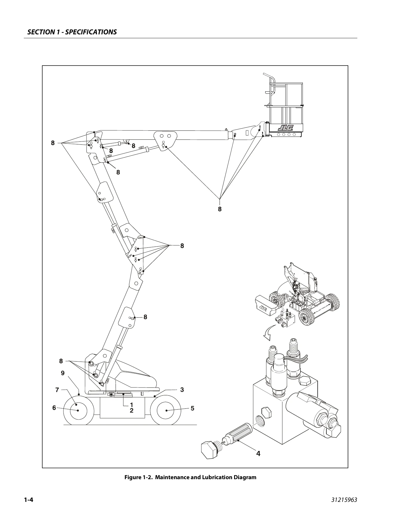
- Section 1 – Specifications: Operating Specifications, Tires, Capacities, Dimensional Data, Torque Specifications, Lubrication Specifications, Hydraulic Oil, Critical Stability Weights, Major Component Weights, Serial Number Locations, Battery Charger Specifications, Maintenance and Lubrication, Threadlocking Compound, SAE and Metric Torque Charts
- Section 2 – General: Machine Preparation, Inspection and Maintenance, Pre-Start Inspection, Pre-Delivery Inspection, Frequent Inspection, Annual Machine Inspection, Preventative Maintenance, Service and Guidelines, Cleanliness, Component Removal and Installation, Pressure-Fit Parts, Bearings, Gaskets, Bolt Usage and Torque Application, Hydraulic Lines and Electrical Wiring, Hydraulic System, Lubrication and Information, Cylinder Drift, Cylinder Leakage Test, Cylinder Thermal Drift, Pins and Composite Bearing Repair Guidelines, Welding on JLG Equipment
- Section 3 – Chassis and Turntable: Tires and Wheels, Tire Damage, Tire Replacement, Wheel Replacement, Wheel Installation, Spindle, Setting Wheel Bearing End Play, Tilt Module, Speed Sensor, Drive Hub, Roll and Leak Testing, Main Disassembly, Output Carrier Disassembly, Input Carrier Disassembly, Hub-Spindle Disassembly, Cover Disassembly, Input Carrier Assembly, Output Planet Gear Assembly, Output Carrier Assembly, Hub-Spindle Assembly, Cover Assembly, Main Assembly, Drive Motor, Swing Bearing, Turntable Bearing Mounting Bolt Condition Check, Wear Tolerance, Replacement of Swing Bearing, Swing Bearing Torque Value, Checking Worm Gear End Play, Adjusting End Play, Swing Motor, Battery Maintenance and Charging, Battery Charger, Generator, Engine, Alternator, Dynamo and Dynamo Voltage Regulator, Start Battery, Engine Starter, Start Control Relay, Fuel Control Relay, Glow Plug Control Relay, Glow Plug, Fuel Pump, Fuel Solenoid, Engine Low Oil Pressure Switch, Engine Oil Temperature Sensor, Alternator Output Current Sensor, Engine Speed Sensor, RBS Engine/Generator Controller, Supplementary Fuse for APU, Counterweight
- Section 4 – Boom and Platform: Platform Support Removal and Installation, Rotator and Platform Level Cylinder Removal and Installation, Main Boom Powertrack, Boom Maintenance, Removal, Disassembly, Inspection, Assembly, Installation, Wear Pads, Boom Cleanliness Guidelines, Boom Limit Switches, Articulating Jib Boom, Boom Synchronizing Procedure, Foot Switch Adjustment, Rotary Actuator, Theory of Operation, Tools Required, Disassembly, Inspection, Assembly, Installing Counterbalance Valve, Greasing Thrust Washers, Testing the Actuator, Installation and Bleeding, Troubleshooting, Powertrack Maintenance, Removing a Link, Installing a New Link, Replacing Fixed End Brackets, Replacing Moving End Brackets, SkyGuard, Operation, Function Test, Diagnostics and Troubleshooting, Bolt-On External Fall Arrest, Inspection Before Use, Installation
- Section 5 – Basic Hydraulic Information and Schematics: Lubricating O-Rings in the Hydraulic System, Cup and Brush, Dip Method, Spray Method, Brush-On Method, Hydraulic Connection Assembly and Torque Specification, Tapered Thread Types, Straight Thread Types, Flange Connection Types, Tightening Methods, Assembly and Torque Specifications, Assembly Instructions for NPTF, BSPT, JIC, SAE, ORFS, DIN 24 Cone, Bulkhead, ORB, MFF, MPP, BSPP, and Flange Connections, Double Wrench Method, FFWR and TFFT Methods, Adjustable Stud End Assembly, O-Ring Installation, Hydraulic Cylinders, Platform Level Cylinder, Jib Lift Cylinder, Lower Lift Cylinder, Mid Lift Cylinder, Upper Lift Cylinder, Master Cylinder, Steer Cylinder, Telescope Cylinder, Cylinder Removal and Installation, Lower Lift Cylinder Bleeding Procedure, Pressure Setting Procedures, Main Relief, Main Lift Down Relief, Lower Lift Down Relief, Telescope Relief, Platform Level Up Relief, Platform Level Down Relief, Steer Relief, Jib Lift Relief, Releveling Valve Relief, Hydraulic Schematic
- Section 6 – JLG Control System: Analyzer Kit Instructions, Introduction, To Connect the JLG Control System Analyzer, Using the Analyzer, Changing the Access Level, Adjusting Parameters, Machine Setup, Level Vehicle Description, Machine Configuration Programming Information, Machine Personality Settings, Machine Orientation When Performing Test, Test Notes, Function Speed, Help Descriptions and Fault Flash Codes, Analyzer Diagnostics Menu Structure, System Self Test, Calibrating Steer, Calibrating Tilt Sensor, Calibrating Load Sensing, LSS System, Diagnostic Menu, Calibration Procedure, Testing and Evaluation, Troubleshooting, Resetting the MSSO System, Drive Cutout Override Service Mode
- Section 7 – Basic Electrical Information and Electrical Schematics: General, Multimeter Basics, Grounding, Backprobing, Min/Max, Polarity, Scale, Voltage Measurement, Resistance Measurement, Continuity Measurement, Current Measurement, Checking Switches, Basic Check, Limit Switches, Automatic Switches, Switch Wiring Low Side and High Side, Applying Silicone Dielectric Compound to Electrical Connections, Dielectric Grease Application, AMP Mate-N-Lok, AMP Faston, AMP Micro-Fit, AMP Mini Fit Jr, Mini Fit Sr, DIN Connectors, Exceptions, AMP Connector, Applying Silicone Dielectric Compound to AMP Connectors, Assembly, Disassembly, Wedge Lock, Service Voltage Reading, DEUTSCH Connectors, DT/DTP Series Assembly and Disassembly, HD30/HDP20 Series Assembly and Disassembly, Wiring Harness Connector Labels, Connector Labels, Component Labels, Electrical Schematics
What This Manual Covers in Depth
This JLG E450AJ service manual opens with a full specifications section that gives you the operating parameters, capacities, and dimensional data for the machine. You get the maximum work load ratings for ANSI and CE/Australia markets, travel speed, gradeability, turning radius, tire load and pressure data, ground bearing pressure, system voltage, battery life per charge, battery recharge times, and gross machine weight. The torque specifications chapter lists wheel lug torque, swing bearing torque, and the intervals at which they must be checked. The lubrication section provides hydraulic oil recommendations by operating temperature range, including Premium Hydraulic Fluid VG 15, Biodegradable Synthetic VG 46, and Hydraulic Gear Fluid 80W-90, with complete specification tables for each. Major component weights and critical stability weights are also listed, along with serial number locations on the frame, turntable, and booms.
The chassis and turntable section covers the complete drive system. You get procedures for tire damage assessment and replacement, wheel installation with torque sequence, spindle end play setting, and greasing requirements. The drive hub chapter walks through roll and leak testing, bolt tightening and torquing, main disassembly, output carrier disassembly, input carrier disassembly, hub-spindle disassembly, cover disassembly, and the complete assembly sequences for each. The drive motor chapter covers removal, disassembly, inspection, assembly, and installation with torque values. The swing bearing chapter includes the turntable bearing mounting bolt condition check, wear tolerance measurement, replacement procedure with torque sequence, worm gear end play checking and adjustment, and the swing bearing torque value. The swing motor chapter provides a full teardown and rebuild procedure with inspection criteria, assembly steps, and final checks. Battery maintenance and charging, the Delta-Q battery charger with fault codes and algorithm selection, and the on-board generator with its RBS engine/generator controller, relays, sensors, and troubleshooting are all covered.
The boom and platform section gives you the procedures to remove and install the platform support, rotator, platform level cylinder, main boom powertrack, and the boom itself. You get wear pad thickness specifications and adjustment, boom cleanliness guidelines, boom limit switch adjustment, articulating jib boom removal and assembly, boom synchronizing procedure, foot switch adjustment, and the complete rotary actuator rebuild with exploded views, seal installation, timing marks, testing, and bleeding. Powertrack maintenance covers removing and installing links, replacing fixed and moving end brackets. SkyGuard operation, function testing, diagnostics and troubleshooting are included, along with the Bolt-On External Fall Arrest inspection and installation.
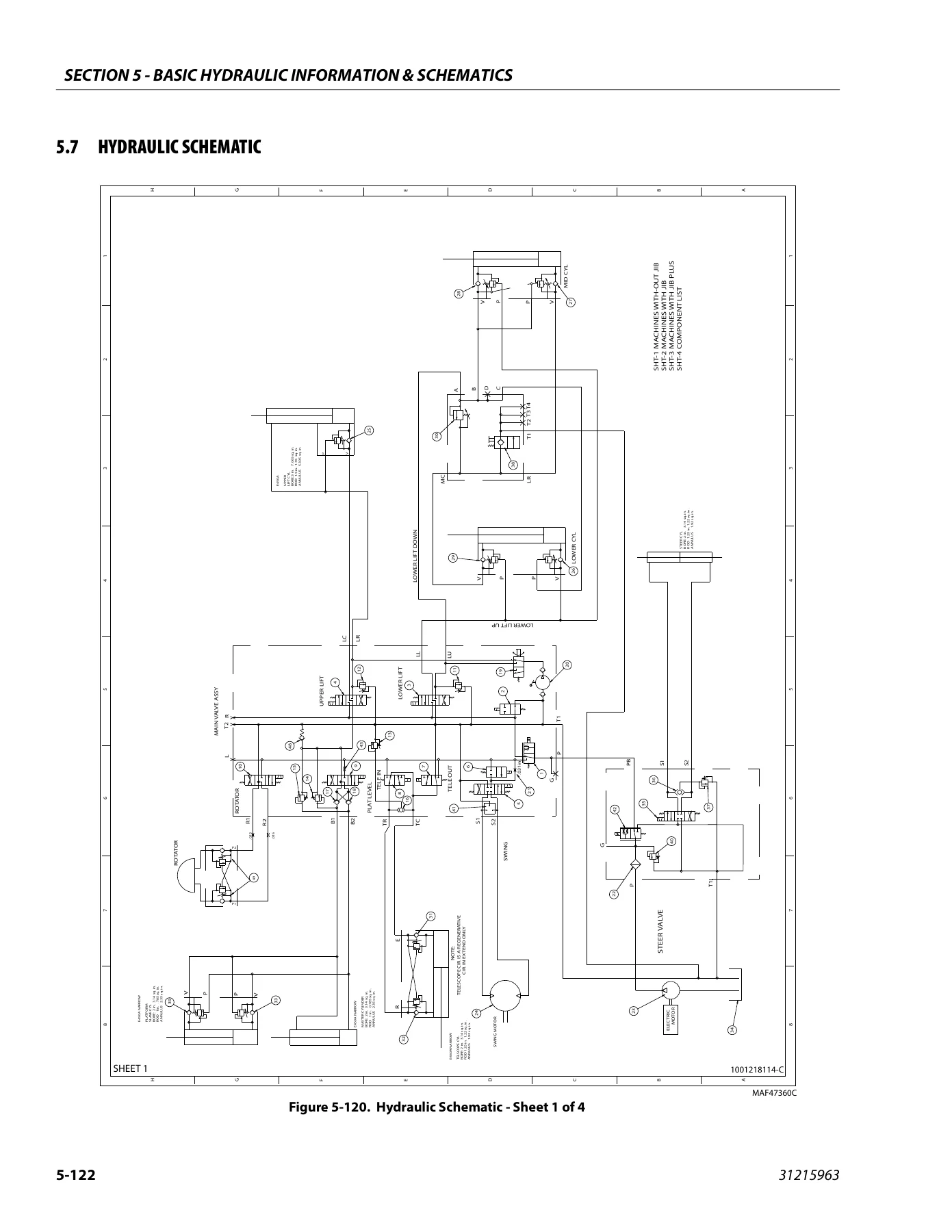
The hydraulic section is extensive. It begins with O-ring lubrication methods, then covers hydraulic connection assembly and torque specifications for NPTF, BSPT, JIC, SAE, ORFS, DIN 24 cone, bulkhead, ORB, MFF, MPP, BSPP, and flange connections, including the double wrench method, FFWR and TFFT methods, and adjustable stud end assembly. Each hydraulic cylinder on the machine has its own chapter with disassembly, cleaning and inspection, and assembly procedures, including the platform level cylinder, jib lift cylinder, lower lift cylinder, mid lift cylinder, upper lift cylinder, master cylinder, steer cylinder, and telescope cylinder. Cylinder removal and installation procedures are given for the main boom lift, mid boom lift, lower boom lift, and main boom telescope cylinders, along with the lower lift cylinder bleeding procedure. Pressure setting procedures cover the main relief, main lift down relief, lower lift down relief, telescope relief, platform level up and down relief, steer relief, jib lift relief, and relevering valve relief. The hydraulic schematic is included.
The JLG control system section explains how to use the hand-held analyzer, change access levels, adjust parameters, and navigate the machine setup. It provides the machine configuration programming information for version P1.12, personality ranges and defaults, function speed specifications, help descriptions and fault flash codes, and the complete analyzer diagnostics menu structure. Calibration procedures are given for steer, tilt sensor, and load sensing. The LSS system chapter covers the diagnostic menu, calibration, testing and evaluation, and troubleshooting. Resetting the MSSO system and the drive cutout override service mode are also documented. The electrical section covers multimeter basics, checking switches, applying dielectric compound, AMP and DEUTSCH connector assembly and disassembly, wiring harness connector labels, and the complete electrical schematics for the platform control box, load sensing system, main valve, turntable, ground control panel, chassis traction, chassis steer/brake, chassis head/tail light, inverter, platform work light, generator, SkyGuard, soft touch, Gen 2 platform interface, and Eboom ClearSky CAN harnesses.
Who This Manual Is For
This JLG E450AJ service manual is written for qualified JLG equipment mechanics, factory-trained service technicians, fleet maintenance managers, and owners who need to perform inspections, preventative maintenance, and repairs on the E450AJ and related models. It assumes you have the tools, training, and experience to work safely on mobile elevating work platforms. The procedures reference specific torque values, service limits, and calibration steps that require a calibrated torque wrench and, for the control system sections, the JLG hand-held analyzer. Whether you are performing a pre-delivery inspection, an annual machine inspection, a frequent inspection, or a full component rebuild, the procedures in this manual give you the sequence, specifications, and safety precautions to do the job correctly.
Why This Manual Matters
Working on a boom lift without the correct service information is risky. The JLG E450AJ has specific torque requirements for the swing bearing bolts, wheel lugs, and hydraulic connections. The hydraulic system operates at high pressures and requires clean assembly practices. The control system needs to be calibrated and configured properly for the machine to operate safely. This manual gives you the exact values, the correct procedures, and the safety precautions that JLG specifies. It covers the machine from the chassis to the platform, so whether you are troubleshooting an electrical fault, rebuilding a hydraulic cylinder, replacing a swing bearing, or calibrating the tilt sensor, you have the reference you need. The exploded views, schematics, and step-by-step procedures help you avoid damage to components and reduce downtime.
Instant PDF Delivery
This JLG E450AJ PVC 2101 Service and Maintenance Manual is delivered as an instant PDF download after payment. There is no shipping, no waiting for a physical book, and no risk of a lost package. You can access the file on any device that reads PDFs, including laptops, tablets, and smartphones. The manual is printable, so you can print the pages you need for the job and keep them in the shop. Whether you are a professional technician, a fleet manager, or an owner-operator, this PDF gives you the complete service and maintenance information for the JLG E450AJ in a convenient, searchable format.
Reviews
There are no reviews yet.