
★ TRUSTED BY 321,897+ PROFESSIONALS WORLDWIDE
🏢
Trusted Business
Verified & Licensed
🛡️
Virus Free Files
100% Safe Downloads
🔒
Secure Payment
SSL Protected
Instant Delivery
Available Immediately
Sale!

JLG G6-42A Telehandler Illustrated Parts Manual 91474001 PDF

Original price was: $44.95.Current price is: $26.95.

Illustrated parts manual for the JLG G6-42A telehandler, document 91474001, revised May 15, 2017. Covers frame, three-section boom, attachments, John Deere, Perkins and Cummins engine installations, Dana and ZF transmissions, Carraro and Dana axles, cab, controls, hydraulic circuits and components, electrical systems, options, recommended spare parts and a part number index. Includes extensive exploded illustrations, part numbers, quantities and serial-number-specific component listings.

Instant PDF Download
Available immediately
💾
Save to Your Device
Download & keep forever
🛡️
Antivirus Scanned
100% virus-free
🌍
Trusted Worldwide
175,000+ customers

Description

JLG G6-42A Telehandler Illustrated Parts Manual 91474001 PDF

This JLG G6-42A Telehandler Illustrated Parts Manual 91474001 PDF is an extensive parts reference for the G6-42A telehandler. The manual is organized around illustrated assemblies and matching parts lists, allowing components to be traced from the machine frame and boom through the drivetrain, hydraulics, electrical equipment, cab and numerous attachments and options. Its coverage is highly serial-number specific, with many assemblies divided into earlier and later configurations so the correct part arrangement can be identified for the machine being serviced.

With 848 PDF pages, this manual goes far beyond a simple replacement-parts list. Exploded and assembly illustrations are paired with item numbers, part numbers, quantities, descriptions and revision information. Many entries also identify replacement or superseded parts, applicable serial ranges, optional configurations, kits, seal kits and related assemblies. The final pages include recommended spare parts and a large part-number index for locating referenced components throughout the manual.

File Details

  • Manual Type: Illustrated Parts Manual
  • Brand: JLG
  • Model: G6-42A
  • Document Number: 91474001
  • Revision: N – Revised Manual
  • Revised: May 15, 2017
  • Language: English
  • Page Count: 850 pages
  • File Format: PDF

Serial Number Coverage

The JLG G6-42A illustrated parts manual identifies its principal machine coverage as SN 0190001 through 0190457 and SN 0160000022 through 0160048656. Individual figures frequently narrow the applicability further. These serial breaks are especially important because the manual shows changes in frame components, boom parts, attachments, engines, transmissions, axles, controls, hydraulic components, electrical harnesses and optional equipment as production configurations changed.

For example, separate illustrations are provided for early and later frame shrouding, axle installations, quick-switch assemblies, attachment configurations, engine installations and numerous hydraulic and electrical components. This makes document 91474001 useful when the same G6-42A component area has more than one production version.

Illustrated Parts and Assembly Reference

The manual uses detailed illustrated views to connect physical components with their corresponding parts listings. Assemblies such as the boom sections, carriage equipment, axles, transmissions, hydraulic cylinders and engine installations are broken down into serviceable items. Parts tables identify the illustrated item number together with the applicable part number, quantity and description. Where applicable, the listings also call out items that are no longer available, replacement part numbers, component kits and references to another section for a deeper breakdown.

IMAGES PREVIEW

JLG G6-42A Telehandler Illustrated Parts Manual 91474001 PDF — PDF page 1 preview
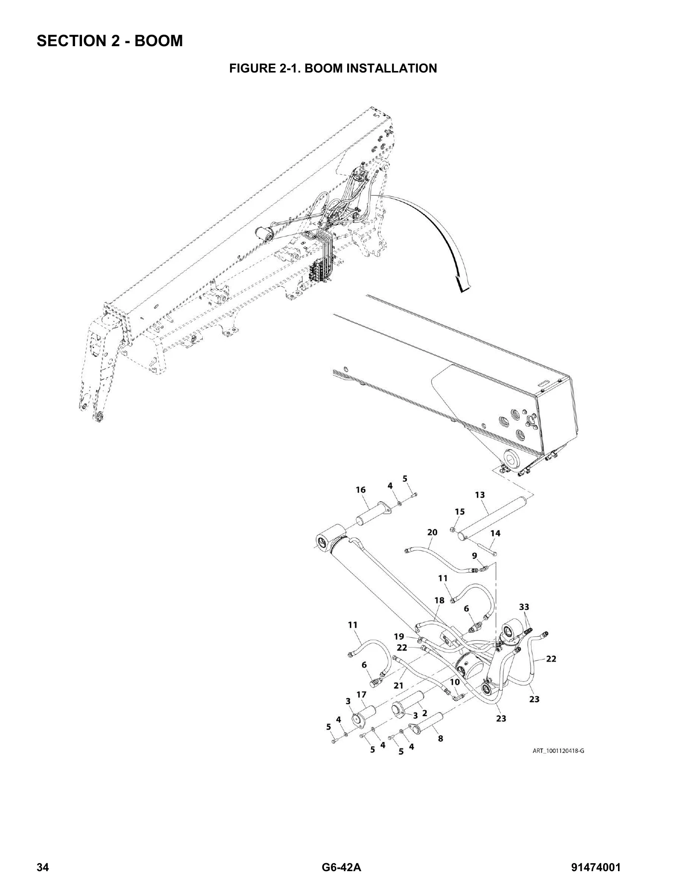
JLG G6-42A Telehandler Illustrated Parts Manual 91474001 PDF — PDF page 34 preview
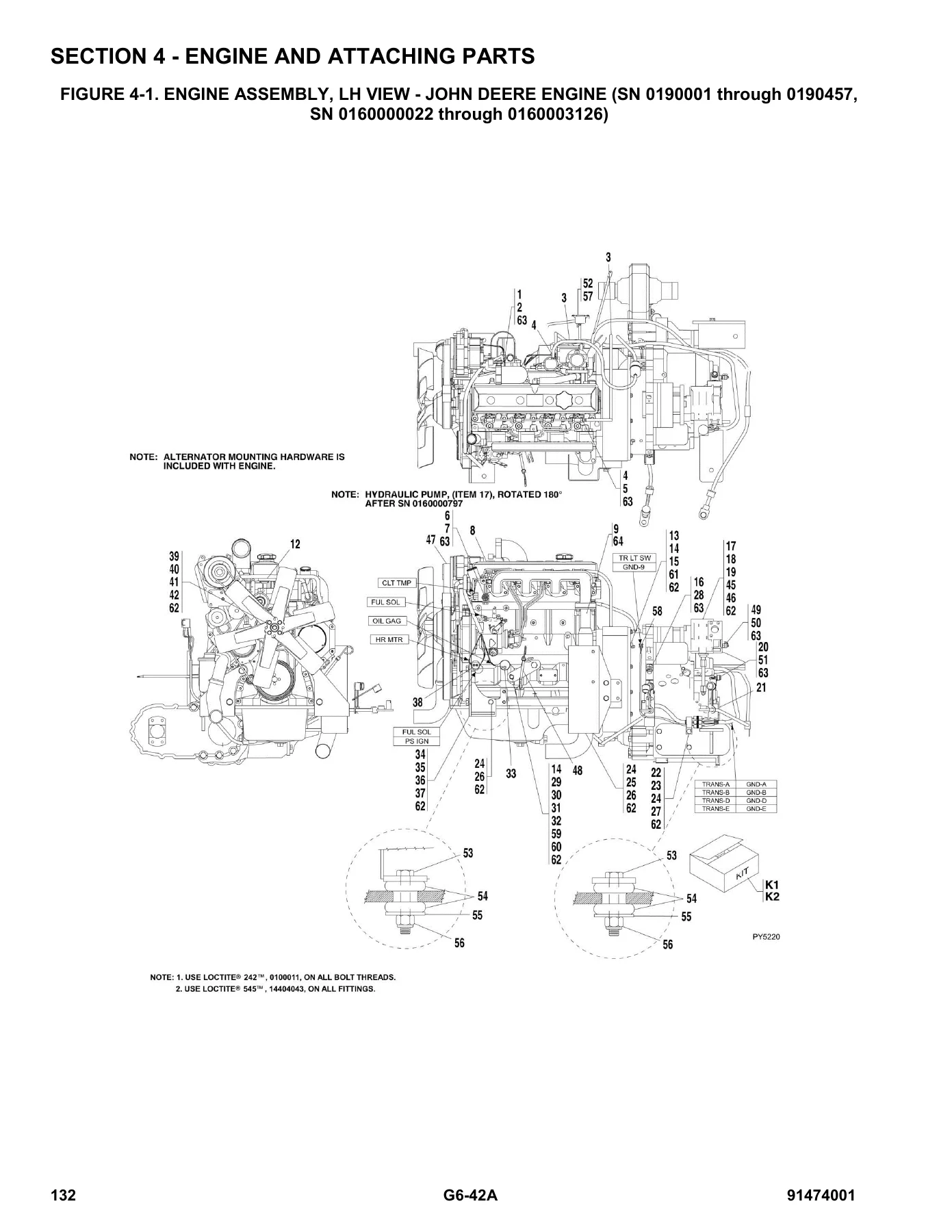
JLG G6-42A Telehandler Illustrated Parts Manual 91474001 PDF — PDF page 132 preview

This is particularly useful for complex assemblies where ordering by appearance alone can be unreliable. The JLG G6-42A parts manual lets the user follow the illustrated assembly, check the serial-number note and then locate the corresponding part listing. Numerous figures also contain fitting, hardware and torque information relevant to the assembly shown.

Engine, Transmission and Drivetrain Variations

The engine and attaching-parts section covers multiple powertrain configurations used in the G6-42A. The manual contains separate illustrated material for John Deere engines, a Perkins engine installation and later Cummins engine configurations. John Deere and Cummins listings in the manual include 99HP configurations, while the Perkins installation is identified by its applicable serial range. Related fuel tank and line arrangements, radiator assemblies, air-cleaner installations and exhaust installations are also divided by engine and serial applicability.

Transmission coverage is similarly detailed. Dana transmission material includes the converter housing, case and plate group, torque converter, gear groups, pump drive, charging pump, reverse idler, forward and reverse shafts, first through third shaft groups, output shaft, electric controls, drive plate and drop box. The later-production coverage also includes ZF transmission installation and assembly views covering the torque converter and input, gearbox housing, forward and reverse gear groups, first through fourth shafts, power take-off, control unit and pressure regulator, gearshift system, oil pump and filter, and transfer box.

The drive train section continues with both Carraro and Dana axle configurations. Front and rear axle assemblies are broken down into housings, steering components, gears, differentials, double joints, brakes, wheel hubs and reduction gears. Drive shaft assemblies plus tires and rims are also included.

Chapters Covered

  • Section 1 – Frame and Attaching Parts: frame shrouding and trim; axle mounting with serial-specific arrangements.
  • Section 2 – Boom: boom installation; first, second and third boom sections; bearing pads, spacers and shims; push beam, extend chain and roller assembly; manual quick switch assemblies.
  • Section 3 – Attachments: tilt and side-tilt carriages; buckets; truss booms and winch versions; adjustable truss boom; swing carriages; sheet material handler; winch installation; drywall swing carriage; personnel and fork-mounted platforms; forks; lifting hooks; grapple bucket; fork pin lock; dual fork positioning carriage; mast assemblies; side-shift carriage.
  • Section 4 – Engine and Attaching Parts: John Deere, Perkins and Cummins engine configurations; fuel tank and lines; radiator, air cleaner and exhaust assemblies; Dana transmission groups; ZF transmission groups.
  • Section 5 – Drive Train: Carraro and Dana front and rear axles; steering and gear components; differentials; brakes; wheel hubs; reduction gears; drive shafts; tires and rims.
  • Section 6 – Cab: open cab; cab enclosures and components; door and glass; suspension seat; dash and instrument panels; rear window exit; skylight wiper installation and motor assembly.
  • Section 7 – Controls: tilt and frame-level joystick; joystick assemblies; accelerator pedal; steering column; brake pedal; auxiliary hydraulic joystick; frame-level joystick.
  • Section 8 – Hydraulic Circuits: priority valve; dump circuit; steer select valve; service and parking circuits; joystick circuit; lift, crowd, tilt, compensating and sway cylinders; auxiliary hydraulics.
  • Section 9 – Hydraulic Components: lift, extend/retract, tilt, compensating and frame-level cylinders; main control valve; implement pump; hydraulic tank; sway and brake valves; priority and steer-select valves; attachment cylinders and auxiliary-control configurations.
  • Section 10 – Electrical: battery and cables; John Deere, Perkins and Cummins engine harnesses; transmission harnesses; cab and control harnesses; lighting harnesses; chassis and park-brake wiring; reverse sensing system; wiper motor harness.
  • Section 11 – Decals: cab and frame decals plus boom decals with serial-specific versions.
  • Section 12 – Options: turbo equipment; heater systems; work lights; cold-start and block-heater installations; stabilizers; auxiliary boom, hydraulic and electrical equipment; beacon and road lights; foam tires; remote oil-filter kits; winch components; seat options; cab glass shields; air-conditioning components; fender and Arctic packages.
  • Section 13 – Recommended Spare Parts: field-service stock recommendations covering boom, engine, drive train, hydraulic, electrical and miscellaneous components, followed by special-tool references and a part-number index.

Complete PDF Bookmark Tree

Complete Bookmarks

The complete bookmarks in the “JLG G6-42A Telehandler Illustrated Parts Manual 91474001 PDF” are as follows:

PM 91474001_N_G6-42A_JLG Partsp. 1
Effectivity Pagep. 3
Table of Contentsp. 5
SECTION 1 – FRAME AND ATTACHING PARTSp. 13
FIGURE 1-1. FRAME SHROUDING AND TRIM (SN 0190001 through 0190457, SN 0160000022 through 0160004023)p. 14
FIGURE 1-2. FRAME SHROUDING AND TRIM (SN 0160004041 through 0160040659)p. 18
FIGURE 1-3. FRAME SHROUDING AND TRIM (SN 0160040678 to Present)p. 22
FIGURE 1-4. AXLE MOUNTING (SN 0190001 through 0190457, SN 0160000022 through 0160000843)p. 28
FIGURE 1-5. AXLE MOUNTING (SN 0160000847 to Present)p. 30
SECTION 2 – BOOMp. 33
FIGURE 2-1. BOOM INSTALLATIONp. 34
FIGURE 2-2. FIRST BOOM SECTIONp. 36
FIGURE 2-3. BEARING PADS, SPACERS AND SHIMS, (FIRST BOOM SECTION)p. 38
FIGURE 2-4. SECOND BOOM SECTIONp. 40
FIGURE 2-5. BEARING PADS, SPACERS AND SHIMS, (SECOND BOOM SECTION)p. 42
FIGURE 2-6. THIRD BOOM SECTIONp. 46
FIGURE 2-7. BEARING PADS, SPACERS AND SHIMS, (THIRD BOOM SECTION)p. 48
FIGURE 2-8. PUSH BEAM/EXTEND CHAIN AND ROLLER ASSEMBLYp. 50
FIGURE 2-9. MANUAL QUICK SWITCH ASSEMBLY (Prior to SN 0160037722)p. 52
FIGURE 2-10. MANUAL QUICK SWITCH ASSEMBLY (SN 0160037722 to Present)p. 54
SECTION 3 – ATTACHMENTSp. 57
FIGURE 3-1. TILT CARRIAGE (Prior to SN 0160023798)p. 58
FIGURE 3-2. TILT CARRIAGE (SN 0160023798 to Present)p. 60
FIGURE 3-3. BUCKETSp. 62
FIGURE 3-4. SIDE TILT CARRIAGE (Prior to SN 0160037722)p. 64
FIGURE 3-5. SIDE TILT CARRIAGE (SN 0160037722 to Present)p. 66
FIGURE 3-6. TRUSS BOOM (Prior to SN 0160037722)p. 68
FIGURE 3-7. TRUSS BOOM (SN 0160037722 to Present)p. 70
FIGURE 3-8. TRUSS BOOM WITH WINCH (Prior to SN 0160037722)p. 72
FIGURE 3-9. TRUSS BOOM WITH WINCH (SN 0160037722 to Present)p. 74
FIGURE 3-10. ADJUSTABLE TRUSS BOOMp. 76
FIGURE 3-11. SWING CARRIAGE (Prior to SN 0160037722)p. 78
FIGURE 3-12. SWING CARRIAGE (SN 0160037722 to Present)p. 82
FIGURE 3-13. SHEET MATERIAL HANDLER (Prior to SN 0160037722)p. 84
FIGURE 3-14. SHEET MATERIAL HANDLER (SN 0160037722 to Present)p. 86
FIGURE 3-15. WINCH INSTALLATIONp. 88
FIGURE 3-16. 100, DRYWALL SWING CARRIAGE ASSEMBLY (Prior to SN 0160037722)p. 90
FIGURE 3-17. PERSONNEL PLATFORM ASSY (Prior to SN 0160037722)p. 94
FIGURE 3-18. FORK MOUNTED PLATFORMp. 96
FIGURE 3-19. 100, SWING CARRIAGE WITH SIDE SHIFT (Prior to SN 0160037722)p. 100
FIGURE 3-20. FORKSp. 104
FIGURE 3-21. FORK MOUNTED LIFTING HOOK PRIOR TO SN 2005134-01p. 106
FIGURE 3-22. FORK MOUNTED LIFTING HOOK SN 2005134-01 TO PRESENTp. 108
FIGURE 3-23. GRAPPLE BUCKETp. 110
FIGURE 3-24. FORK PIN LOCK INSTALLATIONp. 112
FIGURE 3-25. DUAL FORK POSITIONING CARRIAGE ASSEMBLYp. 114
FIGURE 3-26. 6 FT MAST WITH 72 IN CARRIAGE (Prior to SN 0160023798)p. 116
FIGURE 3-27. 8 FT STANDARD MAST (SN 0160023798 to Present)p. 118
FIGURE 3-28. 8 FT SIDE TILT ELECTRIC MAST (SN 0160023798 to Present)p. 122
FIGURE 3-29. 50 IN SIDE SHIFT CARRIAGE (SN 0160023798 to Present)p. 128
SECTION 4 – ENGINE AND ATTACHING PARTSp. 131
FIGURE 4-1. ENGINE ASSEMBLY, LH VIEW – JOHN DEERE ENGINE (SN 0190001 through 0190457, SN 0160000022 through 0160003126)p. 132
FIGURE 4-2. ENGINE ASSEMBLY, LH VIEW – JOHN DEERE ENGINE (SN 0160003208 through 0160040659)p. 136
FIGURE 4-3. ENGINE ASSEMBLY, RH VIEW – JOHN DEERE ENGINE (SN 0190001 through 0190457, SN 0160000022 through 0160003126)p. 140
FIGURE 4-4. ENGINE ASSEMBLY, RH VIEW – JOHN DEERE ENGINE (SN 0160003208 through 0160040659)p. 142
FIGURE 4-5. ENGINE ASSEMBLY – PERKINS ENGINE (SN 0160021195 through 0160040659)p. 146
FIGURE 4-6. ENGINE INSTALLATION – CUMMINS ENGINE (SN 0160040678 to Present)p. 150
FIGURE 4-7. JOHN DEERE ENGINE (SN 0190001 through 0190457, SN 0160000022 through 0160003126)p. 154
FIGURE 4-8. JOHN DEERE ENGINE (SN 0160003208 through 0160006554, Including 0160006659, 0160006662, 0160006665 and 0160006667)p. 158
FIGURE 4-9. JOHN DEERE ENGINE (SN 0160006593 through 0160040659, Excluding 0160006659, 0160006662, 0160006665 and 0160006667)p. 162
FIGURE 4-10. PERKINS ENGINE (SN 0160021195 through 0160040659)p. 166
FIGURE 4-11. CUMMINS ENGINE (SN 0160040678 to Present)p. 168
FIGURE 4-12. FUEL TANK AND LINES (Prior to SN 0160020148)p. 170
FIGURE 4-13. FUEL TANK AND LINES (SN 0160020148 through 0160040659)p. 172
FIGURE 4-14. FUEL TANK AND LINES (SN 0160040678 to Present)p. 174
FIGURE 4-15. RADIATOR ASSEMBLY – JOHN DEERE ENGINE (SN 0190001 through 0190457, SN 01600000022 through 0160003126)p. 176
FIGURE 4-16. RADIATOR ASSEMBLY – JOHN DEERE ENGINE (SN 0160003208 through 0160040659)p. 178
FIGURE 4-17. RADIATOR ASSEMBLY – PERKINS ENGINE (SN 0160021195 through 0160040659)p. 180
FIGURE 4-18. RADIATOR ASSEMBLY – CUMMINS ENGINE (SN 0160040678 to Present)p. 182
FIGURE 4-19. AIR CLEANER AND INSTALLATION – JOHN DEERE ENGINE (SN 0190001 through 0190457, SN 01600000022 through 0160001891)p. 186
FIGURE 4-20. AIR CLEANER AND INSTALLATION – JOHN DEERE ENGINE (SN 0160001893 through 0160003126)p. 188
FIGURE 4-21. AIR CLEANER AND INSTALLATION – JOHN DEERE ENGINE (SN 0160003208 through 0160040659)p. 190
FIGURE 4-22. AIR CLEANER AND INSTALLATION – PERKINS ENGINE (SN 0160021195 through 0160040659)p. 192
FIGURE 4-23. AIR CLEANER AND INSTALLATION – CUMMINS ENGINE (SN 0160040678 to Present)p. 194
FIGURE 4-24. EXHAUST INSTALLATION – JOHN DEERE ENGINE (SN 0190001 through 0190457, SN 01600000022 through 0160003126)p. 196
FIGURE 4-25. EXHAUST INSTALLATION – JOHN DEERE ENGINE (SN 0160003208 through 0160040659)p. 198
FIGURE 4-26. EXHAUST INSTALLATION – PERKINS ENGINE (SN 0160021195 through 0160040659)p. 200
FIGURE 4-27. EXHAUST INSTALLATION – CUMMINS ENGINE (SN 0160040678 to Present)p. 202
FIGURE 4-28. DANA TRANSMISSION INSTALLATION (SN 0160045464 to Present, Including 0160043800)p. 204
FIGURE 4-29. DANA TRANSMISSION – CONVERTER HOUSING GROUP (Prior to SN 0160040678, SN 0160045464 to Present, Including 0160043800)p. 206
FIGURE 4-30. DANA TRANSMISSION CASE AND PLATE GROUP (Prior to SN 0160040678, SN 0160045464 to Present, Including 0160043800)p. 208
FIGURE 4-31. DANA TRANSMISSION – TORQUE CONVERTER GROUP (Prior to SN 0160040678, SN 0160045464 to Present, Including 0160043800)p. 210
FIGURE 4-32. DANA TRANSMISSION – GEAR GROUP (Prior to SN 0160040678)p. 212
FIGURE 4-33. DANA TRANSMISSION – GEAR GROUP (Prior to SN 0160040678, SN 0160045464 to Present, Including 0160043800)p. 214
FIGURE 4-34. DANA TRANSMISSION – PUMP DRIVE GROUP (Prior to SN 0160040678, SN 0160045464 to Present, Including 0160043800)p. 216
FIGURE 4-35. DANA TRANSMISSION – CHARGING PUMP GROUP (Prior to SN 0160040678, SN 0160045464 to Present, Including 0160043800)p. 218
FIGURE 4-36. DANA TRANSMISSION – REVERSE IDLER GROUP (Prior to SN 0160040678, SN 0160045464 to Present, Including 0160043800)p. 220
FIGURE 4-37. DANA TRANSMISSION – FORWARD AND REVERSE SHAFT GROUP (Prior to SN 0160040678, SN 0160045464 to Present, Including 0160043800)p. 222
FIGURE 4-38. DANA TRANSMISSION – 3RD SHAFT GROUP (Prior to SN 0160040678)p. 224
FIGURE 4-39. DANA TRANSMISSION – 3RD SHAFT GROUP (Prior to SN 0160040678, SN 0160045464 to Present, Including 0160043800)p. 226
FIGURE 4-40. DANA TRANSMISSION – FIRST AND SECOND SHAFT GROUP (Prior to SN 0160040678, SN 0160045464 to Present, Including 0160043800)p. 228
FIGURE 4-41. DANA TRANSMISSION – OUTPUT SHAFT GROUP (Prior to SN 0160040678, SN 0160045464 to Present, Including 0160043800)p. 230
FIGURE 4-42. DANA TRANSMISSION – ELECTRIC CONTROL GROUP (Prior to SN 0160040678)p. 232
FIGURE 4-43. DANA TRANSMISSION – ELECTRIC CONTROL GROUP (SN 0190001 through 0190457, SN 01600000022 through 0160011034, Including 0160011878)p. 234
FIGURE 4-44. DANA TRANSMISSION – ELECTRIC CONTROL GROUP (SN 0160011059 through 0160040677, Except SN 0160045464 to Present, Including 0160043800, Excluding 0160011878)p. 236
FIGURE 4-45. DANA TRANSMISSION – DRIVE PLATE GROUP (Prior to SN 0160040678, SN 0160045464 to Present, Including 0160043800)p. 238
FIGURE 4-46. DANA TRANSMISSION – DROP BOX GROUP (Prior to SN 0160040678, SN 0160045464 to Present, Including 0160043800)p. 240
FIGURE 4-47. ZF TRANSMISSION INSTALLATION (SN 0160040678 through 0160045456, Excluding 0160043800)p. 242
FIGURE 4-48. ZF TRANSMISSION ASSEMBLY (SN 0160040678 through 0160045456, Excluding 0160043800)p. 244
FIGURE 4-49. ZF TRANSMISSION – TORQUE CONVERTER AND INPUT (SN 0160040678 through 0160045456, Excluding 0160043800)p. 246
FIGURE 4-50. ZF TRANSMISSION – GEARBOX HOUSING (SN 0160040678 through 0160045456, Excluding 0160043800)p. 248
FIGURE 4-51. ZF TRANSMISSION – FORWARD GEAR GROUP (SN 0160040678 through 0160045456, Excluding 0160043800)p. 250
FIGURE 4-52. ZF TRANSMISSION – REVERSE GEAR GROUP (SN 0160040678 through 0160045456, Excluding 0160043800)p. 252
FIGURE 4-53. ZF TRANSMISSION – 1ST SHAFT GROUP (SN 0160040678 through 0160045456, Excluding 0160043800)p. 254
FIGURE 4-54. ZF TRANSMISSION – 2ND SHAFT GROUP (SN 0160040678 through 0160045456, Excluding 0160043800)p. 256
FIGURE 4-55. ZF TRANSMISSION – 3RD SHAFT GROUP (SN 0160040678 through 0160045456, Excluding 0160043800)p. 258
FIGURE 4-56. ZF TRANSMISSION – 4TH SHAFT GROUP (SN 0160040678 through 0160045456, Excluding 0160043800)p. 260
FIGURE 4-57. ZF TRANSMISSION – POWER TAKE-OFF (SN 0160040678 through 0160045456, Excluding 0160043800)p. 262
FIGURE 4-58. ZF TRANSMISSION – CONTROL UNIT AND PRESSURE REGULATOR (SN 0160040678 through 0160045456, Excluding 0160043800)p. 264
FIGURE 4-59. ZF TRANSMISSION – GEARSHIFT SYSTEM (SN 0160040678 through 0160045456, Excluding 0160043800)p. 266
FIGURE 4-60. ZF TRANSMISSION – OIL PUMP, FILTER AND DIPSTICK (SN 0160040678 through 0160045456, Excluding 0160043800)p. 268
FIGURE 4-61. ZF TRANSMISSION – TRANSFER BOX (SN 0160040678 through 0160045456, Excluding 0160043800)p. 270
SECTION 5 – DRIVE TRAINp. 273
FIGURE 5-1. FRONT AXLE INSTALLATION – CARRARO (SN 0190001 through 0190457, SN 0160000022 through 0160000843)p. 274
FIGURE 5-2. FRONT AXLE – CARRARO (SN 0190001 through 0190457, SN 0160000022 through 0160000843)p. 276
FIGURE 5-3. FRONT AXLE HOUSING ASSEMBLY – CARRARO (SN 0190001 through 0190457, SN 0160000022 through 0160000843)p. 278
FIGURE 5-4. FRONT STEERING COMPONENTS – CARRARO (SN 0190001 through 0190457, SN 0160000022 through 0160000843)p. 280
FIGURE 5-5. FRONT GEAR COMPONENTS – CARRARO (SN 0190001 through 0190457, SN 0160000022 through 0160000843)p. 282
FIGURE 5-6. FRONT DIFFERENTIAL – CARRARO (SN 0190001 through 0190457, SN 0160000022 through 0160000843)p. 284
FIGURE 5-7. FRONT DOUBLE JOINT – CARRARO (SN 0190001 through 0190457, SN 0160000022 through 0160000843)p. 286
FIGURE 5-8. FRONT BRAKES – CARRARO (SN 0190001 through 0190457, SN 0160000022 through 0160000843)p. 288
FIGURE 5-9. FRONT WHEEL HUB – CARRARO (SN 0190001 through 0190457, SN 0160000022 through 0160000843)p. 290
FIGURE 5-10. FRONT REDUCTION GEARS – CARRARO (SN 0190001 through 0190457, SN 0160000022 through 0160000843)p. 292
FIGURE 5-11. REAR AXLE INSTALLATION – CARRARO (SN 0190001 through 0190457, SN 0160000022 through 0160000843)p. 294
FIGURE 5-12. REAR AXLE – CARRARO (SN 0190001 through 0190457, SN 0160000022 through 0160000843)p. 296
FIGURE 5-13. REAR AXLE HOUSING ASSEMBLY – CARRARO (SN 0190001 through 0190457, SN 0160000022 through 0160000843)p. 298
FIGURE 5-14. REAR STEERING COMPONENTS – CARRARO (SN 0190001 through 0190457, SN 0160000022 through 0160000843)p. 300
FIGURE 5-15. REAR GEAR COMPONENTS – CARRARO (SN 0190001 through 0190457, SN 0160000022 through 0160000843)p. 302
FIGURE 5-16. REAR DIFFERENTIAL – CARRARO (SN 0190001 through 0190457, SN 0160000022 through 0160000843)p. 304
FIGURE 5-17. REAR DOUBLE JOINT – CARRARO (SN 0190001 through 0190457, SN 0160000022 through 0160000843)p. 306
FIGURE 5-18. REAR WHEEL HUB – CARRARO (SN 0190001 through 0190457, SN 0160000022 through 0160000843)p. 308
FIGURE 5-19. REAR REDUCTION GEARS – CARRARO (SN 0190001 through 0190457, SN 0160000022 through 0160000843)p. 310
FIGURE 5-20. FRONT AXLE INSTALLATION – DANA (SN 0160000847 through 0160040659)p. 312
FIGURE 5-21. FRONT AXLE INSTALLATION – DANA (SN 0160040678 to Present)p. 314
FIGURE 5-22. FRONT AXLE – DANA (SN 0160000847 to Present)p. 316
FIGURE 5-23. FRONT AXLE HOUSING ASSEMBLY – DANA (SN 0160000847 to Present)p. 318
FIGURE 5-24. FRONT STEERING COMPONENTS – DANA (SN 0160000847 to Present)p. 320
FIGURE 5-25. FRONT GEAR COMPONENTS – DANA (SN 0160000847 to Present)p. 322
FIGURE 5-26. FRONT DIFFERENTIAL – DANA (SN 0160000847 to Present)p. 324
FIGURE 5-27. FRONT DOUBLE JOINT – DANA (SN 0160000847 to Present)p. 326
FIGURE 5-28. FRONT BRAKES – DANA (SN 0160000847 to Present)p. 328
FIGURE 5-29. FRONT WHEEL HUB – DANA (SN 0160000847 to Present)p. 330
FIGURE 5-30. FRONT REDUCTION GEARS – DANA (SN 0160000847 to Present)p. 332
FIGURE 5-31. REAR AXLE INSTALLATION – DANA (SN 0160000847 through 0160040659)p. 334
FIGURE 5-32. REAR AXLE INSTALLATION – DANA (SN 0160040678 to Present)p. 336
FIGURE 5-33. REAR AXLE – DANA (SN 0160000847 to Present)p. 338
FIGURE 5-34. REAR AXLE HOUSING ASSEMBLY – DANA (SN 0160000847 to Present)p. 340
FIGURE 5-35. REAR STEERING COMPONENTS – DANA (SN 0160000847 to Present)p. 342
FIGURE 5-36. REAR GEAR COMPONENTS – DANA (SN 0160000847 to Present)p. 344
FIGURE 5-37. REAR DIFFERENTIAL – DANA (SN 0160000847 to Present)p. 346
FIGURE 5-38. REAR DOUBLE JOINT – DANA (SN 0160000847 to Present)p. 348
FIGURE 5-39. REAR BRAKES – DANA (SN 0160000847 through 0160037722, Including 0160037786)p. 350
FIGURE 5-40. REAR BRAKES – DANA (SN 0160037749 to Present, Excluding 0160037786)p. 352
FIGURE 5-41. REAR WHEEL HUB – DANA (SN 0160000847 to Present)p. 354
FIGURE 5-42. REAR REDUCTION GEARS – DANA (SN 0160000847 to Present)p. 356
FIGURE 5-43. DRIVE SHAFT ASSEMBLY (SN 0190001 through 0190457, SN 0160000022 through 0160000843)p. 358
FIGURE 5-44. DRIVE SHAFT ASSEMBLY (SN 0160000847 to Present)p. 360
FIGURE 5-45. TIRES AND RIMSp. 362
SECTION 6 – CABp. 365
FIGURE 6-1. OPEN CABp. 366
FIGURE 6-2. CAB ENCLOSURESp. 368
FIGURE 6-3. CAB COMPONENTSp. 370
FIGURE 6-4. CAB DOOR ASSEMBLYp. 372
FIGURE 6-5. CAB GLASSp. 374
FIGURE 6-6. SUSPENSION SEATp. 376
FIGURE 6-7. DASH PANEL (Prior to SN 0160040678)p. 378
FIGURE 6-8. DASH PANEL (SN 0160040678 to Present)p. 380
FIGURE 6-9. INSTRUMENT PANEL (SN 0190001 through 0190457, SN 0160000022 through 0160001277)p. 382
FIGURE 6-10. INSTRUMENT PANEL (SN 0160001283 through 0160040659)p. 384
FIGURE 6-11. INSTRUMENT PANEL (SN 0160040678 to Present)p. 386
FIGURE 6-12. REAR WINDOW EXIT INSTALLATIONp. 390
FIGURE 6-13. SKYLIGHT WIPER INSTALLATIONp. 392
FIGURE 6-14. SKYLIGHT WIPER MOTOR ASSEMBLYp. 394
SECTION 7 – CONTROLSp. 397
FIGURE 7-1. TILT AND FRAME LEVEL JOYSTICK INSTALLATIONp. 398
FIGURE 7-2. JOYSTICK ASSEMBLYp. 400
FIGURE 7-3. ACCELERATOR PEDAL INSTALLATION (Prior to SN 0160038504, Excluding 0160025238)p. 402
FIGURE 7-4. ACCELERATOR PEDAL INSTALLATION (SN 0160038504 through 0160040659, Including 0160025238)p. 404
FIGURE 7-5. ACCELERATOR PEDAL INSTALLATION (SN 0160040678 to Present)p. 406
FIGURE 7-6. STEERING COLUMN AND ATTACHING PARTS (Prior to SN 0160040678)p. 408
FIGURE 7-7. STEERING COLUMN AND ATTACHING PARTS (SN 0160040678 to Present)p. 410
FIGURE 7-8. BRAKE PEDAL INSTALLATION (SN 0190001 through 0190457, SN 0160000022 through 0160000843)p. 412
FIGURE 7-9. BRAKE PEDAL INSTALLATION (SN 0160000847 through 0160029241)p. 414
FIGURE 7-10. BRAKE PEDAL INSTALLATION (SN 0160029242 through 0160040659)p. 416
FIGURE 7-11. BRAKE PEDAL INSTALLATION (SN 0160040678 to Present)p. 418
FIGURE 7-12. JOYSTICK ASSEMBLYp. 420
FIGURE 7-13. JOYSTICK ASSEMBLYp. 422
FIGURE 7-14. AUXILIARY HYDRAULIC JOYSTICK INSTALLATIONp. 424
FIGURE 7-15. FRAME LEVEL JOYSTICK INSTALLATIONp. 426
SECTION 8 – HYDRAULIC CIRCUITSp. 429
FIGURE 8-1. PRIORITY VALVE (SN 0190001 through 0190457, SN 0160000022 through 0160021166)p. 430
FIGURE 8-2. PRIORITY VALVE (SN 0160021195 through 0160022113)p. 432
FIGURE 8-3. PRIORITY VALVE (SN 0160022163 through 0160040659)p. 434
FIGURE 8-4. PRIORITY VALVE (SN 0160040678 to Present)p. 436
FIGURE 8-5. DUMP CIRCUIT (Prior to SN 0160040678)p. 440
FIGURE 8-6. DUMP CIRCUIT (SN 0160040678 to Present)p. 442
FIGURE 8-7. STEER SELECT VALVE (Prior to SN 0160040678)p. 444
FIGURE 8-8. STEER SELECT VALVE (SN 0160040678 to Present)p. 446
FIGURE 8-9. SERVICE/PARKING (SN 0190001 through 0190457, SN 0160000022 through 0160000843)p. 448
FIGURE 8-10. SERVICE/PARKING (SN 0160000847 through 0160040659)p. 450
FIGURE 8-11. SERVICE/PARKING (SN 0160040678 to Present)p. 452
FIGURE 8-12. JOYSTICK CIRCUIT (Prior to SN 0160040678)p. 454
FIGURE 8-13. JOYSTICK CIRCUIT (SN 0160040678 to Present)p. 456
FIGURE 8-14. LIFT CYLINDER (Prior to SN 0160040678)p. 458
FIGURE 8-15. LIFT CYLINDER (SN 0160040678 to Present)p. 460
FIGURE 8-16. CROWD CYLINDER (Prior to SN 0160040678)p. 462
FIGURE 8-17. CROWD CYLINDER (SN 0160040678 to Present)p. 464
FIGURE 8-18. TILT AND TILT COMPENSATING CYLINDER (Prior to SN 0160040678)p. 466
FIGURE 8-19. TILT AND TILT COMPENSATING CYLINDER (SN 0160040678 to Present)p. 470
FIGURE 8-20. SWAY CYLINDER (Prior to SN 0160040678)p. 472
FIGURE 8-21. SWAY CYLINDER (SN 0160040678 to Present)p. 474
FIGURE 8-22. AUXILIARY HYDRAULICS (SN 0160040678 to Present)p. 476
SECTION 9 – HYDRAULIC COMPONENTSp. 479
FIGURE 9-1. LIFT CYLINDER (SN 0190001 through 0190457, SN 0160000022 through 0160007820)p. 480
FIGURE 9-2. LIFT CYLINDER (SN 0160007868 through 0160007974)p. 482
FIGURE 9-3. LIFT CYLINDER (SN 0160008059 through 0160010475)p. 484
FIGURE 9-4. LIFT CYLINDER (SN 0160010497 through 0160033619)p. 486
FIGURE 9-5. LIFT CYLINDER (SN 0160033656 to Present)p. 488
FIGURE 9-6. LIFT CYLINDER (SN 0160035857 to Present)p. 490
FIGURE 9-7. EXTEND/RETRACT CYLINDER – IOWA (SN 0190001 through 0190457, SN 0160000022 through 0160033619)p. 492
FIGURE 9-8. EXTEND/RETRACT CYLINDER – TEXAS HYDRAULICS (SN 0160033656 to Present)p. 494
FIGURE 9-9. EXTEND/RETRACT CYLINDERp. 496
FIGURE 9-10. TILT CYLINDER – IOWA (SN 0190001 through 0190457, SN 0160000022 through 0160033619)p. 498
FIGURE 9-11. TILT CYLINDER – TEXAS HYDRAULICS (SN 0160033656 to Present)p. 500
FIGURE 9-12. COMPENSATING CYLINDER (SN 0190001 through 0190457, SN 0160000022 through 0160007820)p. 502
FIGURE 9-13. COMPENSATING CYLINDER (SN 0160007868 through 0160007974)p. 504
FIGURE 9-14. COMPENSATING CYLINDER (SN 0160008059 through 0160017476)p. 506
FIGURE 9-15. COMPENSATING CYLINDER (SN 0160017503 to Present)p. 508
FIGURE 9-16. FRAME LEVEL CYLINDER (SN 0190001 through 0190446)p. 510
FIGURE 9-17. FRAME LEVEL CYLINDER (SN 0190447 through 0190457, SN 0160000022 through 0160033619)p. 512
FIGURE 9-18. FRAME LEVEL CYLINDER (SN 0160033656 to Present)p. 514
FIGURE 9-19. FRAME LEVEL CYLINDER (ARCTIC)p. 516
FIGURE 9-20. MAIN CONTROL VALVE (Prior to SN 0160037722)p. 518
FIGURE 9-21. MAIN CONTROL VALVE (SN 0160037722 to Present)p. 522
FIGURE 9-22. IMPLEMENT PUMP (SN 0190001 through 0190457, SN 0160000022 through 0160000715)p. 526
FIGURE 9-23. IMPLEMENT PUMP (SN 0160000797 through 0160040677)p. 528
FIGURE 9-24. IMPLEMENT PUMP (SN 0160040678 to Present)p. 530
FIGURE 9-25. HYDRAULIC TANK ASSEMBLY (Prior to SN 0160040678)p. 532
FIGURE 9-26. HYDRAULIC TANK ASSEMBLY (SN 0160040678 to Present)p. 534
FIGURE 9-27. SWAY CYLINDER VALVE (SN 0190001 through 0190357)p. 536
FIGURE 9-28. SWAY CYLINDER VALVE (SN 0160000022 to Present, SN 0190358 through 0190457)p. 538
FIGURE 9-29. BRAKE VALVE (SN 0190001 through 0190457, SN 0160000022 through 0160000843)p. 540
FIGURE 9-30. BRAKE VALVE (SN 0160000847 through 0160029212)p. 544
FIGURE 9-31. BRAKE VALVE (SN 0160029242 through 0160040659)p. 548
FIGURE 9-32. BRAKE VALVE (SN 0160040678 to Present)p. 552
FIGURE 9-33. PRIORITY VALVE (SN 0190001 through 0190457, SN 0160000022 through 0160001862)p. 556
FIGURE 9-34. PRIORITY VALVE (SN 0160001866 through 0160022230)p. 558
FIGURE 9-35. PRIORITY VALVE (SN 0160022231 to Present)p. 560
FIGURE 9-36. STEER SELECT VALVE (Prior to SN 0160004856)p. 562
FIGURE 9-37. STEER SELECT VALVE (SN 0160004856 through 0160040659)p. 564
FIGURE 9-38. STEER SELECT VALVE (SN 0160040678 to Present)p. 566
FIGURE 9-39. GRAPPLE BUCKET CYLINDERp. 568
FIGURE 9-40. SIDE TILT CARRIAGE CYLINDERp. 570
FIGURE 9-41. 72IN 90, SWING CARRIAGE CYLINDERp. 572
FIGURE 9-42. MAIN CONTROL VALVE, TILT ON JOYSTICK WITH AUX (SN 0160040678 to Present)p. 574
FIGURE 9-43. 50 IN SIDE SHIFT CARRIAGE CYLINDER (SN 0160023798 to Present)p. 578
SECTION 10 – ELECTRICALp. 581
FIGURE 10-1. BATTERY AND CABLES (Prior to SN 0160040678)p. 582
FIGURE 10-2. BATTERY AND CABLES (SN 0160040678 to Present)p. 584
FIGURE 10-3. ENGINE HARNESS – JOHN DEERE ENGINE (SN 0190001 through 0190457, SN 0160000022 through 0160002053)p. 586
FIGURE 10-4. ENGINE HARNESS – JOHN DEERE ENGINE (SN 0160002056 through 0160006654, Including 0160006659, 0160006662, 0160006665 and 0160006667)p. 588
FIGURE 10-5. ENGINE HARNESS – JOHN DEERE ENGINE (SN 0160006593 through 0160011034, Excluding 0160006659, 0160006662, 0160006665 and 0160006667)p. 590
FIGURE 10-6. ENGINE HARNESS – JOHN DEERE ENGINE (SN 0160011059 through 0160018126)p. 592
FIGURE 10-7. ENGINE HARNESS – JOHN DEERE ENGINE (SN 0160018150 through 0160021166)p. 594
FIGURE 10-8. ENGINE HARNESS – JOHN DEERE ENGINE (SN 0160021195 through 0160040659)p. 596
FIGURE 10-9. ENGINE HARNESS – PERKINS ENGINE (SN 0160021195 through 0160040659)p. 598
FIGURE 10-10. ENGINE HARNESS – CUMMINS ENGINE (SN 0160040678 to Present)p. 602
FIGURE 10-11. TRANSMISSION HARNESS (SN 0160045464 to Present, SN 0160021195 through 0160040677, Including 0160043800)p. 604
FIGURE 10-12. TRANSMISSION HARNESS (SN 0160040678 through 0160045456, Excluding 0160043800)p. 606
FIGURE 10-13. CAB WORK LIGHT HARNESS (SN 0160035560 to Present)p. 608
FIGURE 10-14. ENCLOSED CAB HARNESS (SN 0160040678 to Present)p. 610
FIGURE 10-15. CAB CONTROL HARNESS (Prior to SN 0160045456, Excluding 0160043800)p. 612
FIGURE 10-16. CAB CONTROL HARNESS (SN 0160045464 to Present, Including 0160043800)p. 614
FIGURE 10-17. CAB DASH HARNESS (SN 0160040678 to Present)p. 616
FIGURE 10-18. VEC BOX HARNESS (SN 0160040678 to Present)p. 618
FIGURE 10-19. TILT AND AUX CONTROL MODULE (SN 0160040678 to Present)p. 620
FIGURE 10-20. ACCESSORY MODULE HARNESS (SN 0160040678 to Present)p. 622
FIGURE 10-21. FRAME ROAD LIGHTS HARNESSp. 624
FIGURE 10-22. CAB ROAD LIGHTS HARNESSp. 626
FIGURE 10-23. CAB WORK LIGHT HARNESSp. 628
FIGURE 10-24. BOOM WORK LIGHTS HARNESSp. 630
FIGURE 10-25. CAB WORK LIGHT AND BEACON LIGHT HARNESS (Prior to SN 0160040678)p. 632
FIGURE 10-26. CHASSIS HARNESS (SN 0160040678 to Present)p. 634
FIGURE 10-27. PARK BRAKE HARNESSp. 638
FIGURE 10-28. REVERSE SENSING SYSTEM INSTALLATIONp. 640
FIGURE 10-29. REVERSE SENSOR HARNESSp. 642
FIGURE 10-30. WIPER MOTOR HARNESSp. 644
SECTION 11 – DECALSp. 647
FIGURE 11-1. CAB AND FRAME DECALS (SN 0190001 through 0190457, SN 0160000022 through 0160003959)p. 648
FIGURE 11-2. CAB AND FRAME DECALS (SN 0160003986 through 0160040063)p. 652
FIGURE 11-3. CAB AND FRAME DECALS (SN 0160040169 to Present)p. 656
FIGURE 11-4. BOOM DECALS (SN 0190001 through 0190457, SN 0160000022 through 0160006219)p. 662
FIGURE 11-5. BOOM DECALS (SN 0160006238 to Present)p. 664
SECTION 12 – OPTIONSp. 667
FIGURE 12-1. TURBO OPTION (SN 0190001 through 0190457, SN 0160000022 through 0160003126)p. 668
FIGURE 12-2. TURBO ENGINE ASSEMBLY, LH VIEW (SN 0190001 through 0190457, SN 0160000022 through 0160003126)p. 670
FIGURE 12-3. TURBO ENGINE ASSEMBLY, RH VIEW (SN 0190001 through 0190457, SN 0160000022 through 0160003126)p. 674
FIGURE 12-4. JOHN DEERE TURBO ENGINE (SN 0190001 through 0190457, SN 0160000022 through 0160003126)p. 676
FIGURE 12-5. TURBO RADIATOR ASSEMBLY (SN 0190001 through 0190457, SN 0160000022 through 0160003126)p. 680
FIGURE 12-6. TURBO AIR CLEANER AND INSTALLATION (SN 0190001 through 0190457, SN 0160000022 through 0160001891)p. 682
FIGURE 12-7. TURBO AIR CLEANER AND INSTALLATION (SN 0160001893 through 0160003126)p. 684
FIGURE 12-8. TURBO EXHAUST INSTALLATION (SN 0190001 through 0190457, SN 0160000022 through 0160003126)p. 686
FIGURE 12-9. ENCLOSED CAB HEATER COMPONENTS (SN 0190001 through 0190457, SN 0160000022 through 0160015432)p. 688
FIGURE 12-10. ENCLOSED CAB HEATER COMPONENTS (SN 0160015458 through 0160040659)p. 692
FIGURE 12-11. ENCLOSED CAB HEATER COMPONENTS (SN 0160040678 to Present)p. 696
FIGURE 12-12. OPEN CAB HEATER COMPONENTS (SN 0160015458 through 0160040659)p. 698
FIGURE 12-13. OPEN CAB HEATER COMPONENTS (SN 0160021195 through 0160040659)p. 700
FIGURE 12-14. OPEN CAB HEATER COMPONENTS (SN 0160040678 to Present)p. 702
FIGURE 12-15. ENGINE HEATER COMPONENTSp. 704
FIGURE 12-16. WORKLIGHT PACKAGE (SN 0190001 through 0160000843, SN 0160000847 through 0160031618)p. 706
FIGURE 12-17. COLD START INSTALLATION – JOHN DEERE ENGINE (Prior to SN 0160040678)p. 712
FIGURE 12-18. BLOCK HEATER INSTALLATION – JOHN DEERE ENGINE (Prior to SN 0160040678)p. 714
FIGURE 12-19. STABILIZER OPTION (SN 0190001 through 0190457, SN 0160000022 through 0160000843)p. 716
FIGURE 12-20. STABILIZER OPTION (SN 0160000847 through 0160040659)p. 718
FIGURE 12-21. STABILIZER CYLINDERp. 720
FIGURE 12-22. TILT ON JOYSTICK WITH RH FRAME LEVEL (Prior to SN 0160040678)p. 722
FIGURE 12-23. AUXILIARY BOOM ASSEMBLY (Prior to SN 0160037722)p. 726
FIGURE 12-24. AUXILIARY BOOM ASSEMBLY (SN 0160037722 to Present)p. 728
FIGURE 12-25. LH AUXILIARY HYDRAULIC ASSEMBLY (Prior to SN 0160040678)p. 730
FIGURE 12-26. AUXILIARY ELECTRICS ASSEMBLY (Prior to SN 0160037722)p. 732
FIGURE 12-27. AUXILIARY ELECTRICS ASSEMBLY (SN 0160037722 through 0160040659)p. 736
FIGURE 12-28. MAIN CONTROL VALVE WITH AUXILIARY HYDRAULICS (Prior to SN 0160037722)p. 740
FIGURE 12-29. BEACON LIGHT PACKAGE (Prior to SN 0160031634)p. 744
FIGURE 12-30. FOAM TIRE OPTIONp. 746
FIGURE 12-31. REMOTE OIL FILTER KIT (Prior to SN 0160040678)p. 748
FIGURE 12-32. TURBO REMOTE ENGINE OIL FILTER KIT (Prior to SN 0160040678)p. 750
FIGURE 12-33. SWAY CYLINDER (Prior to SN 0160038600)p. 752
FIGURE 12-34. SWING CYLINDERp. 754
FIGURE 12-35. TRUSS BOOM WINCHp. 756
FIGURE 12-36. WINCH MOTORp. 760
FIGURE 12-37. TRUSS BOOM PRESSURE REDUCER VALVE – 1200 PSIp. 762
FIGURE 12-38. TRUSS BOOM PRESSURE REDUCER VALVE – 1360 PSIp. 764
FIGURE 12-39. STARTER KIT (SN 0190001 through 0190457, SN 0160000022 through 016006554, Including 0160006659, 0160006662, 0160006665 and 0160006667)p. 766
FIGURE 12-40. FUEL/WATER SEPARATOR INSTALLATION – JOHN DEERE ENGINE (Prior to SN 0160040678)p. 768
FIGURE 12-41. SUSPENSION SEAT OPTION (SN 0190001 through 0190457, SN 0160000022 through 0160015432)p. 770
FIGURE 12-42. STANDARD SEAT REPLACEMENT KIT (SN 0160015458 to Present)p. 772
FIGURE 12-43. HEAVY SEAT REPLACEMENT KIT (SN 0160015458 through 0160040659)p. 774
FIGURE 12-44. WORK LIGHT INSTALLATION (SN 0160031634 through 0160040659)p. 776
FIGURE 12-45. WORK LIGHT INSTALLATION (SN 0160040678 to Present)p. 780
FIGURE 12-46. ROAD LIGHTS INSTALLATION (Prior to SN 0160040678)p. 782
FIGURE 12-47. ROAD LIGHTS INSTALLATION (SN 0160040678 to Present)p. 786
FIGURE 12-48. BEACON LIGHT INSTALLATION (SN 0160031634 through 0160040659)p. 788
FIGURE 12-49. BEACON LIGHT INSTALLATION (SN 0160040678 to Present)p. 790
FIGURE 12-50. COUNTERWEIGHT WITH PINTLE HOOKp. 792
FIGURE 12-51. TOP CAB GLASS SHIELDp. 794
FIGURE 12-52. FRONT CAB GLASS SHIELDp. 796
FIGURE 12-53. ENGINE AIR CONDITIONING COMPONENTS PERKINS (Prior to SN 0160040678)p. 798
FIGURE 12-54. ENGINE AIR CONDITIONING COMPONENTS JOHN DEERE (Prior to SN 0160040678)p. 800
FIGURE 12-55. ENGINE AIR CONDITIONING COMPONENTS CUMMINS (SN 0160040678 to Present)p. 802
FIGURE 12-56. AIR CONDITIONING COMPONENTS (Prior to SN 0160040678)p. 804
FIGURE 12-57. AIR CONDITIONING COMPONENTS (SN 0160040678 to Present)p. 808
FIGURE 12-58. WINCHp. 812
FIGURE 12-59. FENDER INSTALLATIONp. 814
FIGURE 12-60. SWING CYLINDERp. 816
FIGURE 12-61. ARCTIC PACKAGE (SN 0160021195 through 0160040659)p. 818
FIGURE 12-62. ARCTIC PACKAGE (SN 0160040678 to Present)p. 820
SECTION 13 – RECOMMENDED SPARE PARTSp. 823
FIGURE 13-1. RECOMMENDED SPARE PARTSp. 824
PART NUMBER INDEXp. 829

Taken together, these chapters provide a machine-wide illustrated parts reference rather than coverage of only one subsystem. The user can move from the main structure and boom into attachment hardware, powertrain configurations, axle assemblies, operator-station parts, hydraulic circuits and individual hydraulic components, then continue into electrical equipment and optional packages. The extensive part-number index at the rear provides another route for tracing a known number back to its location in the manual.

Attachments and Optional Equipment

A major strength of the JLG G6-42A Telehandler Illustrated Parts Manual 91474001 PDF is the breadth of attachment coverage. The manual illustrates several carriage configurations as well as buckets, forks, grapple equipment, lifting hooks, truss booms, winch arrangements, material-handling platforms, dual fork positioning equipment and mast assemblies. Earlier and later attachment designs are separated where the production serial break requires it.

The options section adds further detail for equipment that may not appear on every machine. It covers turbo-related components, enclosed and open cab heater arrangements, engine heaters, work-light packages, cold-start equipment, stabilizers, auxiliary boom and hydraulic assemblies, auxiliary electrical systems, beacon lights, remote oil-filter arrangements, truss-boom winch components, seat configurations, road lights, glass shields, air-conditioning arrangements for the different engine installations, and Arctic packages.

Recommended Spare Parts and Part Number Index

Near the end of the manual, JLG provides a recommended spare-parts section intended to identify field-replaceable stock for fleets. It includes items associated with the boom, engine configurations, drive train, hydraulic systems, electrical equipment and miscellaneous machine items. Examples include filter kits, belts, cylinder seal kits, hydraulic filters, electrical senders and switches, starters, alternators and selected axle-related service parts. Special tools associated with Carraro axles, Dana axles and the Dana transmission are also referenced.

The part-number index begins after the recommended-spares section and links individual part numbers back to pages where they appear. For anyone starting with an existing JLG number rather than an assembly location, this index can significantly simplify navigation through such a large parts manual.

Identify the Correct G6-42A Parts Before Ordering

The JLG G6-42A Telehandler Illustrated Parts Manual 91474001 PDF is designed to support accurate component identification across the machine’s frame, boom, attachments, engines, transmissions, axles, cab, controls, hydraulics, electrical system and options. Exploded illustrations, item references, part numbers, quantities and detailed serial-number breaks help you compare the actual machine configuration with the correct parts arrangement before ordering or planning service work.

That detail matters on a G6-42A because many assemblies changed across production ranges and the manual documents those differences directly. Using the appropriate illustration and serial-specific listing helps reduce the risk of selecting a component from the wrong configuration and provides a practical reference when inspecting or dismantling an assembly.

After purchase, the manual is supplied as an instant PDF download. There is no physical book and no shipping delay. You can open the PDF on a computer, tablet or compatible mobile device and print the pages or sections you need for workshop or parts-counter reference.
Reviews

There are no reviews yet.

Be the first to review “JLG G6-42A Telehandler Illustrated Parts Manual 91474001 PDF”

What Our Customers Say

★★★★★ Live reviews from customers
Loading customer reviews...
0
    0
    Your Cart
    Your cart is emptyReturn to Shop
    🛒
    Recently Purchased
    🕒 verified order