
★ TRUSTED BY 321,897+ PROFESSIONALS WORLDWIDE
🏢
Trusted Business
Verified & Licensed
🛡️
Virus Free Files
100% Safe Downloads
🔒
Secure Payment
SSL Protected
Instant Delivery
Available Immediately
Sale!

SkyTrak 8042 10042 10054 Illustrated Parts Manual – 8990395 Telehandler Parts Catalog PDF

Original price was: $34.95.Current price is: $19.95.

Complete illustrated parts manual for SkyTrak 8042, 10042 and 10054 telehandlers. Publication 8990395 covering frame, boom, attachments, engine, drive train, cab, hydraulics, electrical and decals with exploded views and part numbers.

Instant PDF Download
Available immediately
💾
Save to Your Device
Download & keep forever
🛡️
Antivirus Scanned
100% virus-free
🌍
Trusted Worldwide
175,000+ customers

Description

SkyTrak 8042, 10042 and 10054 Illustrated Parts Manual – Publication 8990395

This illustrated parts manual covers the SkyTrak 8042, 10042 and 10054 telehandlers. It is the complete parts catalog identified by publication number 8990395, organized into sections that mirror the machine’s assembly: frame, boom, attachments, engine, drive train, cab, controls, hydraulic circuits, hydraulic components, electrical, decals, options and recommended spare parts. Every figure is an exploded illustration with a corresponding parts table listing item numbers, part numbers, quantities and descriptions.

File Details

  • Manual type: Illustrated Parts Manual
  • Brand: SkyTrak (JLG)
  • Models covered: 8042, 10042, 10054
  • Publication number: 8990395
  • Language: English
  • Page count: 602 pages
  • File format: PDF

Chapters Covered

  • Section 1 – Frame and Attaching Parts: Main frame components, hoods and guards, outrigger mounting
  • Section 2 – Boom: First boom section, second boom section, third boom section, fourth boom section, quick attach, boom extend chains, boom retract chains
  • Section 3 – Attachments: Buckets, tilt carriage, side tilt carriage, swing carriage, sheet material handler, truss booms, lifting hook, forks, concrete bucket, sweeper assembly, fork mounted platform, grapple bucket, fork pin lock, dual fork positioning carriage, 8 ft standard mast, side shift carriage
  • Section 4 – Engine and Attaching Parts: Engine mounting, fuel system, radiator and oil cooler mounting, air cleaner assembly, exhaust system, isolation coupler
  • Section 5 – Drive Train: Drive train components, front axle, rear axle, ZF transmission, drive shafts, tires and rims
  • Section 6 – Cab: Open cab, closed cab, soft cab enclosure, cab door, operators seat, windshield wipers, cab heater
  • Section 7 – Controls: Service brake pedal, throttle pedal, steering wheel and shifter, control console, boom lift/lower and extend/retract control, frame sway and attachment tilt control, auxiliary hydraulic control
  • Section 8 – Hydraulic Circuits: Service brake and de-clutch, boom lift/lower and extend/retract, attachment tilt and slave, frame sway and stabil-trak, outriggers, power steering, control valve, auxiliary hydraulic, transmission cooler
  • Section 9 – Hydraulic Components: Extend/retract cylinder, lift/lower cylinder, attachment tilt cylinder, frame sway cylinder, stabil-trak cylinder, slave cylinder, outrigger cylinder, piston pump, main control valve, directional control valve, fuel/hydraulic tank, side tilt carriage cylinder, swing carriage cylinder, grapple bucket cylinder, brake valve, side shift carriage cylinder
  • Section 10 – Electrical: Cab harness, engine harness, outrigger harness, jumper harness
  • Section 11 – Decals: Decals prior to SN 0160029593, decals SN 0160029593 to present
  • Section 12 – Options: Worklight system, roadlight system, swing carriage cylinder, side tilt carriage cylinder, fender installation, rotating beacon, first boom section service kit, remote oil filler, ignition switch weather kit, exhaust upgrade kit
  • Section 13 – Recommended Spare Parts: Recommended spare parts list
  • Part Number Index

Complete PDF Bookmark Tree

Complete Bookmarks

The complete bookmarks in the “SkyTrak 8042 10042 10054 Illustrated Parts Manual – 8990395 Telehandler Parts Catalog PDF” are as follows:

8990395_U_8042_10042_10054_SkyTrak_Partsp. 1
EFFECTIVITY PAGEp. 3
TABLE OF CONTENTSp. 5
SECTION 1 – FRAME AND ATTACHING PARTSp. 13
FIGURE 1-1. MAIN FRAME COMPONENTS (SN 13198 through 19987, SN 0160002332 through 0160004669)p. 14
FIGURE 1-2. MAIN FRAME COMPONENTS (8042 SN 0160004670 through 0160033642; 10042 SN 0160004670 through 0160033649; 10054 SN 0160004670 through 0160033644)p. 16
FIGURE 1-3. MAIN FRAME COMPONENTS (8042 SN 0160033643 to Present; 10042 SN 0160033650 to Present; 10054 SN 0160033645 to Present)p. 20
FIGURE 1-4. HOODS AND GUARDS (8042 SN 13198 through 0160029592; 10042 SN 13198 through 0160029606; 10054 SN 13198 through 0160029593)p. 22
FIGURE 1-5. HOODS AND GUARDS (8042 SN 0160029593 to Present; 10042 SN 0160029607 to Present; 10054 SN 0160029594 to Present)p. 24
FIGURE 1-6. OUTRIGGER MOUNTING 10042/10054p. 26
SECTION 2 – BOOMp. 29
FIGURE 2-1. FIRST BOOM SECTION (SN 13198 through 19987, SN 0160002332 through 0160004670)p. 30
FIGURE 2-2. FIRST BOOM SECTION (SN 0160004671 through 0160015024)p. 32
FIGURE 2-3. FIRST BOOM SECTION (SN 0160015042 to Present)p. 34
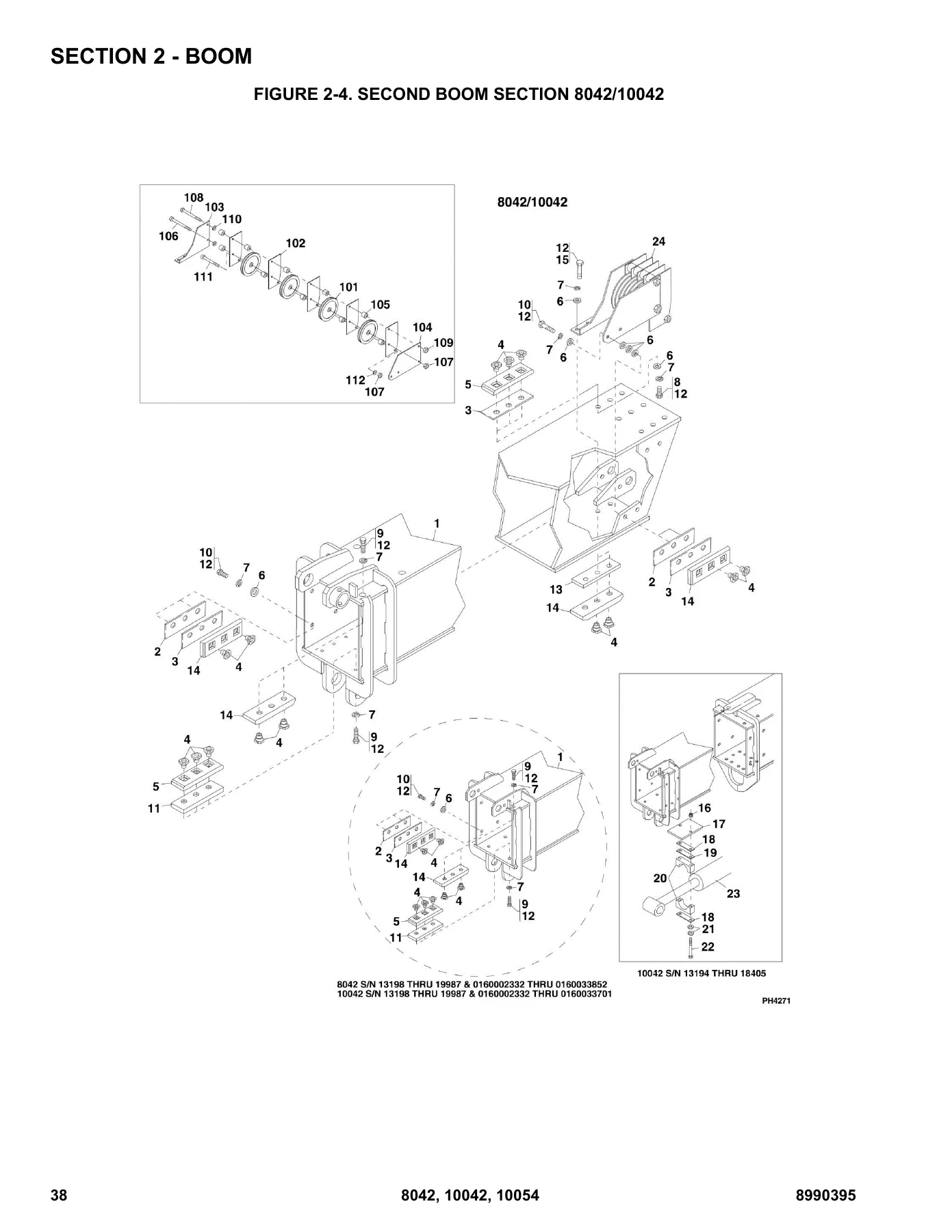
FIGURE 2-4. SECOND BOOM SECTION 8042/10042p. 38
FIGURE 2-5. SECOND BOOM SECTION 10054p. 40
FIGURE 2-6. THIRD BOOM SECTION 8042/10042p. 42
FIGURE 2-7. THIRD BOOM SECTION 10054p. 44
FIGURE 2-8. FOURTH BOOM SECTION 10054p. 46
FIGURE 2-9. QUICK ATTACHp. 48
FIGURE 2-10. BOOM EXTEND CHAINS 8042/10042p. 50
FIGURE 2-11. BOOM EXTEND CHAINS 10054p. 52
FIGURE 2-12. BOOM RETRACT CHAINS 8042/10042p. 54
FIGURE 2-13. BOOM RETRACT CHAINS 10054p. 56
SECTION 3 – ATTACHMENTSp. 59
FIGURE 3-1. BUCKETSp. 60
FIGURE 3-2. TILT CARRIAGE (8042 SN 13198 through 19987, SN 0160002332 through 0160034158; 10042 SN 13198 through 19987, SN 0160002332 through 0160033709; 10054 SN 13198 through 19987, SN 0160002332 through 0160034159)p. 62
FIGURE 3-3. TILT CARRIAGE (8042 SN 0160034159 to Present; 10042 SN 0160033710 to Present; 10054 SN 0160034160 to Present)p. 64
FIGURE 3-4. SIDE TILT CARRIAGE (8042 Prior to SN 0160037799; 10042 Prior to SN 0160037798; 10054 Prior to SN 0160037793)p. 66
FIGURE 3-5. SIDE TILT CARRIAGE (8042 SN 0160037799 to Present; 10042 SN 0160037798 to Present; 10054 SN 0160037793 to Present)p. 68
FIGURE 3-6. SWING CARRIAGE (8042 Prior to SN 0160037799; 10042 Prior to SN 0160037798; 10054 Prior to SN 0160037793)p. 70
FIGURE 3-7. SWING CARRIAGE (8042 SN 0160037799 to Present; 10042 SN 0160037798 to Present; 10054 SN 0160037793 to Present)p. 72
FIGURE 3-8. SHEET MATERIAL HANDLER (8042 Prior to SN 0160037799; 10042 Prior to SN 0160037798; 10054 Prior to SN 0160037793)p. 74
FIGURE 3-9. SHEET MATERIAL HANDLER (8042 SN 0160037799 to Present; 10042 SN 0160037798 to Present; 10054 SN 0160037793 to Present)p. 76
FIGURE 3-10. 3 FT TRUSS BOOM WITH WINCHp. 78
FIGURE 3-11. 12 FT TRUSS BOOM WITH WINCHp. 80
FIGURE 3-12. TRUSS BOOM (8042 Prior to SN 0160037799; 10042 Prior to SN 0160037798; 10054 Prior to SN 0160037793)p. 82
FIGURE 3-13. TRUSS BOOM (8042 SN 0160037799 to Present; 10042 SN 0160037798 to Present; 10054 SN 0160037793 to Present)p. 84
FIGURE 3-14. LIFTING HOOKp. 86
FIGURE 3-15. FORKSp. 88
FIGURE 3-16. CONCRETE BUCKETp. 90
FIGURE 3-17. SWEEPER ASSEMBLYp. 92
FIGURE 3-18. FORK MOUNTED PLATFORMp. 94
FIGURE 3-19. GRAPPLE BUCKETp. 98
FIGURE 3-20. FORK PIN LOCK INSTALLATIONp. 100
FIGURE 3-21. DUAL FORK POSITIONING CARRIAGE ASSEMBLYp. 102
FIGURE 3-22. 8 FT STANDARD MASTp. 104
FIGURE 3-23. SIDE SHIFT CARRIAGE ASSEMBLY (50 INCH), (INCLUDES ALL ITEMS)p. 108
SECTION 4 – ENGINE AND ATTACHING PARTSp. 111
FIGURE 4-1. ENGINE MOUNTING (8042 SN 13198 through 18990; 10042 SN 13198 through 19030; 10054 SN 13198 through 19079)p. 112
FIGURE 4-2. ENGINE MOUNTING (8042 SN 18991 through 19987, SN 0160002332 through 0160029586; 10042 SN 19031 through 19987, SN 0160002332 through 0160029586; 10054 SN 19080 through 19987, SN 0160002332 through 0160029586)p. 114
FIGURE 4-3. ENGINE MOUNTING (8042 SN 0160029593 through 0160038983; 10054 SN 0160029593 through 0160038983; 10042 SN 0160029593 through 0160038370)p. 118
FIGURE 4-4. ENGINE MOUNTING (8042 & 10054 SN 0160038984 through 0160040218, Excluding 0160039850, 0160040126, 0160040127, 0160040128, 0160040129 and 0160040171; 10042 SN 0160038371 through 0160040218, Excluding 0160039850, 0160040126, 0160040127, 0160…p. 122
FIGURE 4-5. ENGINE MOUNTING (SN 0160040220 to Present, Including 0160039850, 0160040126, 0160040127, 0160040128, 0160040129 and 0160040171)p. 126
FIGURE 4-6. FUEL SYSTEM (8042 SN 13198 through 18990; 10042 SN 13198 through 19030; 10054 SN 13198 through 19079)p. 130
FIGURE 4-7. FUEL SYSTEM (8042 SN 18991 through 19987, SN 0160002332 through 0160029592; 10042 SN 19031 through 19987, SN 0160002332 through 0160029606; 10054 SN 19080 through 19987, SN 0160002332 through 0160029593)p. 132
FIGURE 4-8. FUEL SYSTEM (8042 & 10054 SN 0160029593 through 0160040218, Excluding 0160039850, 0160040126, 0160040127, 0160040128, 0160040129 and 0160040171; 10042 SN 0160029607 through 0160040218, Excluding 0160039850, 0160040126, 0160040127, 01600401…p. 134
FIGURE 4-9. FUEL SYSTEM (SN 0160040220 to Present, SN 0160040126 through 0160040129, Including 0160039850 and 0160040171)p. 136
FIGURE 4-10. RADIATOR AND OIL COOLER MOUNTING (8042 SN 13198 through 18990; 10042 SN 13198 through 19030; 10054 SN 13198 through 19079)p. 138
FIGURE 4-11. RADIATOR AND OIL COOLER MOUNTING (8042 SN 18991 through 19987, SN 0160002332 through 0160010788; 10042 SN 19031 through 19987, SN 0160002332 through 0160010788; 10054 SN 19080 through 19987, SN 0160002332 through 0160010788)p. 140
FIGURE 4-12. RADIATOR AND OIL COOLER MOUNTING (8042 SN 0160010789 through 0160029592; 10042 SN 0160010789 through 0160029606; 10054 SN 0160010789 through 0160029592)p. 144
FIGURE 4-13. RADIATOR AND OIL COOLER MOUNTING (8042 & 10054 SN 0160029593 through 0160038983; 10042 SN 0160029607 through 0160038370)p. 146
FIGURE 4-14. RADIATOR AND OIL COOLER MOUNTING (8042 SN 0160038984 through 0160040218, Excluding 0160039850, 0160040126, 0160040127, 0160040128, 0160040129 and 0160040171; 10054 SN 0160038984 through 0160040218, Excluding 0160039850, 0160040126, 016004…p. 150
FIGURE 4-15. RADIATOR AND OIL COOLER MOUNTING (SN 0160040220 to Present, Including 0160039850, 0160040126, 0160040127, 0160040128, 0160040129 and 0160040171)p. 154
FIGURE 4-16. AIR CLEANER ASSEMBLY (8042 SN 13198 through 18990; 10042 SN 13198 through 19030; 10054 SN 13198 through 19079)p. 156
FIGURE 4-17. AIR CLEANER ASSEMBLY (8042 SN 18991 through 19987, SN 0160002332 through 0160029592; 10042 SN 19031 through 19987, SN 0160002332 through 0160029606; 10054 SN 19080 through 19987, SN 0160002332 through 0160029592)p. 158
FIGURE 4-18. AIR CLEANER ASSEMBLY (8042 SN 0160029593 through 0160040218, Excluding 0160039850, 0160040126, 0160040127, 0160040128, 0160040129 and 0160040171; 10054 SN 0160029593 through 0160040218, Excluding 0160039850, 0160040126, 0160040127, 016004…p. 160
FIGURE 4-19. AIR CLEANER ASSEMBLY (SN 0160040220 to Present, Including 0160039850, 0160040126, 160040127, 160040128, 160040129 and 0160040171)p. 162
FIGURE 4-20. EXHAUST SYSTEM (8042 SN 13198 through 18990; 10042 SN 13198 through 19030; 10054 SN 13198 through 19079)p. 164
FIGURE 4-21. EXHAUST SYSTEM (8042 SN 18991 through 19987, SN 0160002332 through 0160029592; 10042 SN 19031 through 19987, SN 0160002332 through 0160029606; 10054 SN 19080 through 19987, SN 0160002332 through 0160029592)p. 166
FIGURE 4-22. EXHAUST SYSTEM (8042 SN 0160029593 through 0160035236; 10042 SN 0160029607 through 0160035245; 10054 SN 0160029594 through 0160035235)p. 168
FIGURE 4-23. EXHAUST SYSTEM (8042 SN 0160035236 through 0160040218, Excluding 0160039850, 0160040126, 0160040127, 0160040128, 0160040129 and 0160040171; 10054 SN 0160035236 through 0160040218, Excluding 0160039850, 0160040126, 0160040127, 0160040128, …p. 170
FIGURE 4-24. EXHAUST SYSTEM (SN 0160040220 to Present, Including 0160039850, 0160040126, 0160040127, 0160040128, 0160040129 and 0160040171)p. 172
FIGURE 4-25. ISOLATION COUPLER (8042 SN 13198 through 18990; 10042 SN 13198 through 19030; 10054 SN 13198 through 19079)p. 174
FIGURE 4-26. ISOLATION COUPLER (8042 SN 18991 through 19987, SN 0160002332 to Present; 10042 SN 19031 through 19987, SN 0160002332 to Present; 10054 SN 19080 through 19987, SN 0160002332 to Present)p. 176
SECTION 5 – DRIVE TRAINp. 179
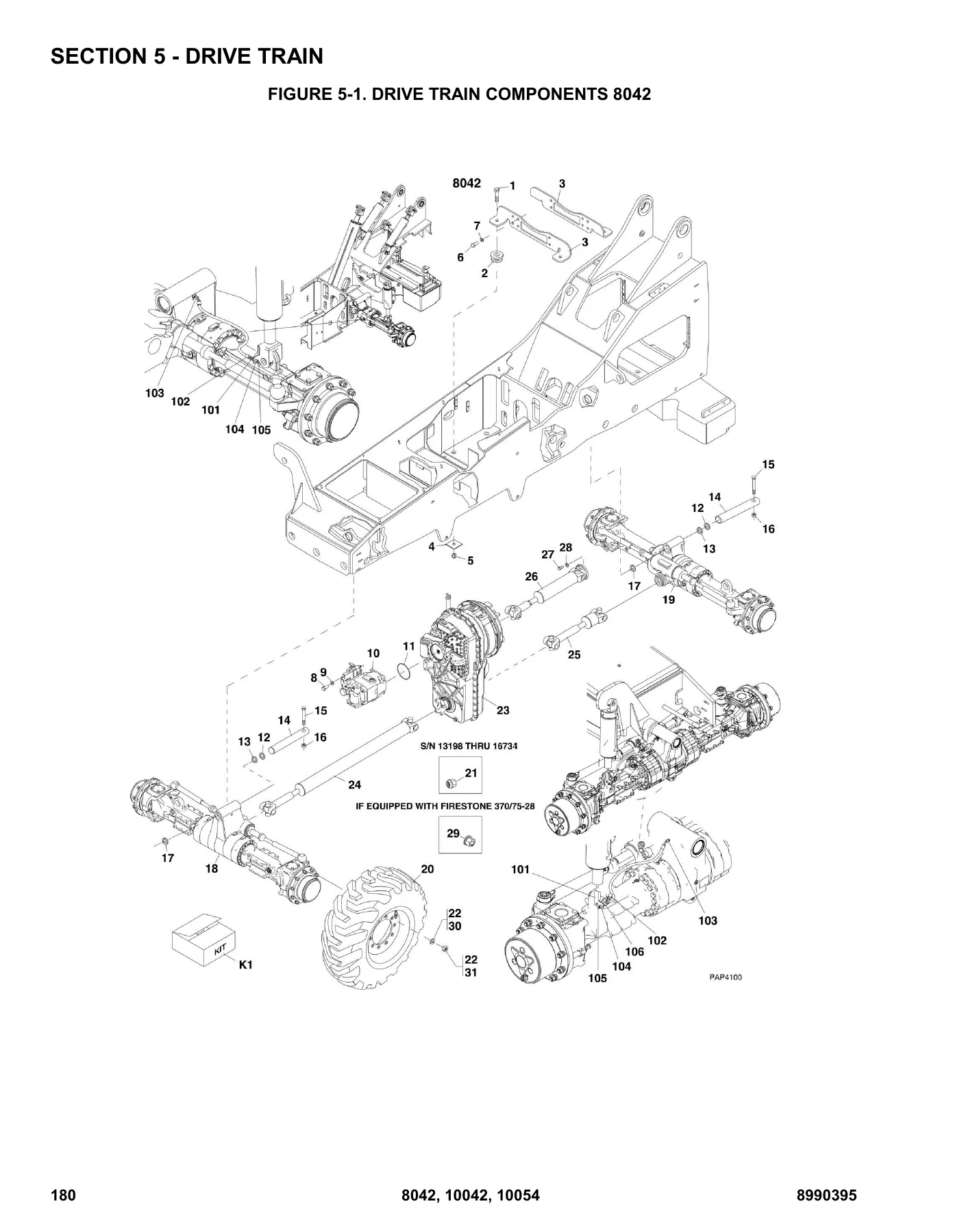
FIGURE 5-1. DRIVE TRAIN COMPONENTS 8042p. 180
FIGURE 5-2. DRIVE TRAIN COMPONENTS 10042 AND 10054p. 184
FIGURE 5-3. FRONT AXLEp. 188
FIGURE 5-4. FRONT AXLE – INPUT (8042 Prior to SN 0160038967, Including 0160038971 and 0160038984; 10042 Prior to SN 0160038368, Including 0160038375, 0160038378, 0160038379, 0160038381 and 0160038383; 10054 Prior to SN 0160038740, Excluding 0160021270…p. 190
FIGURE 5-5. FRONT AXLE – INPUT (8042 SN 0160038967 to Present, Excluding 0160038971 and 0160038984; 10042 SN 0160038368 to Present, Excluding 0160038375, 0160038378, 0160038379, 0160038381 and 0160038383; 10054 SN 0160038740 to Present, Including 0160…p. 194
FIGURE 5-6. FRONT AXLE – LIMITED SLIP DIFFERENTIAL (8042 Prior to SN 0160038967, Including 0160038971 and 0160038984; 10042 Prior to SN 0160038368, Including 0160038368, 0160038375, 0160038378, 0160038379, 0160038381 and 0160038383; 10054 Prior to SN …p. 198
FIGURE 5-7. FRONT AXLE – LIMITED SLIP DIFFERENTIAL (8042 SN 0160038967 to Present, Excluding 0160038971 and 0160038984; 10042 SN 0160038368 to Present, Excluding 0160038375, 0160038378, 0160038379, 0160038381 and 0160038383; 10054 SN 0160038740 to Pre…p. 200
FIGURE 5-8. FRONT AXLE – AXLE CASING (8042 Prior to SN 0160038967, Including 0160038971 and 0160038984; 10042 Prior to SN 0160038368, Including 0160038375, 0160038378, 016003837910042 and 0160038383; 10054 Prior to SN 0160038740, Excluding 0160021270,…p. 202
FIGURE 5-9. FRONT AXLE – AXLE CASING (8042 SN 0160038967 to Present, Excluding 0160038971 and 0160038984; 10042 SN 0160038368 to Present, Excluding 0160038375, 0160038378, 0160038379, 0160038381 and 0160038383; 10054 SN 0160038740 to Present, Includin…p. 204
FIGURE 5-10. FRONT AXLE – M-DISC BRAKE (8042 Prior to SN 0160038967; Including 0160038971 and 0160038984)p. 206
FIGURE 5-11. FRONT AXLE – M-DISC BRAKE (10042 Prior to SN 0160038368, Including 0160038375, 0160038378, 0160038379, 0160038381 and 0160038383; 10054 Prior to SN 0160038740, Excluding 0160021270, 0160036713, 0160036715, 0160036721 and 0160036723)p. 210
FIGURE 5-12. FRONT AXLE – M-DISC BRAKE (8042 SN 0160038967 to Present, Excluding 0160038971 and 0160038984; 10042 SN 0160038368 to Present, Excluding 0160038375, 0160038378, 0160038379, 0160038381 and 0160038383; 10054 SN 0160038740 to Present, Includ…p. 214
FIGURE 5-13. FRONT AXLE – BRAKE (8042 Prior to SN 0160038967, Including 0160038971 and 0160038984; 10042 Prior to SN 0160038368, Including 0160038375, 0160038378, 0160038379, 0160038381 and 0160038383; 10054 Prior to SN 0160038740, Excluding 016002127…p. 216
FIGURE 5-14. FRONT AXLE – BRAKE (8042 SN 0160038967 to Present, Excluding 0160038971 and 0160038984; 10042 SN 0160038368 to Present, Excluding 0160038375, 0160038378, 0160038379, 0160038381 and 0160038383; 10054 SN 0160038740 to Present, Including 016…p. 218
FIGURE 5-15. FRONT AXLE – JOINT HOUSING (8042 Prior to SN 0160038967, Including 0160038971 and 0160038984; 10042 Prior to SN 0160038368, Including 0160038375, 0160038378, 0160038379, 0160038381 and 0160038383; 10054 Prior to SN 0160038740, Excluding 0…p. 220
FIGURE 5-16. FRONT AXLE – JOINT HOUSING (8042 SN 0160038967 to Present, Excluding 0160038971 and 0160038984; 10042 SN 0160038368 to Present, Excluding 0160038375, 0160038378, 0160038379, 0160038381 and 0160038383; 10054 SN 0160038740 to Present, Inclu…p. 224
FIGURE 5-17. FRONT AXLE – PLANETARY DRIVE (8042 Prior to SN 0160038967, Including 0160038971 and 0160038984; 10042 Prior to SN 0160038368, Including 0160038375, 0160038378, 0160038379, 0160038381 and 0160038383; 10054 Prior to SN 0160038740, Excluding…p. 226
FIGURE 5-18. FRONT AXLE – PLANETARY DRIVE (8042 SN 0160038967 to Present, Excluding 0160038971 and 0160038984; 10042 SN 0160038368 to Present, Excluding 0160038375, 0160038378, 0160038379, 0160038381 and 0160038383; 10054 SN 0160038740 to Present, Inc…p. 228
FIGURE 5-19. REAR AXLEp. 230
FIGURE 5-20. REAR AXLE – INPUT (8042 Prior to SN 0160038967, Including 0160038971 and 0160038984; 10042 Prior to SN 0160038368, Including 0160038375, 0160038378, 0160038379, 0160038381 and 0160038383; 10054 Prior to SN 0160038740, Excluding 0160021270…p. 232
FIGURE 5-21. REAR AXLE – INPUT (8042 SN 0160038967 to Present, Excluding 0160038971 and 0160038984; 10042 SN 0160038368 to Present, Excluding 0160038375, 0160038378, 0160038379, 0160038381 and 0160038383; 10054 SN 0160038740 to Present, Including 0160…p. 236
FIGURE 5-22. REAR AXLE – DIFFERENTIAL 8 (8042 Prior to SN 0160038967, Including 0160038971 and 0160038984; 10042 Prior to SN 0160038368, Including 0160038375, 0160038378, 0160038379, 0160038381 and 0160038383; 10054 Prior to SN 0160038740; 10058 Exclu…p. 240
FIGURE 5-23. REAR AXLE – DIFFERENTIAL (8042 SN 0160038967 to Present, Excluding 0160038971 and 0160038984; 10042 SN 0160038368 to Present, Excluding 0160038375, 0160038378, 0160038379, 0160038381 and 0160038383; 10054 SN 0160038740 to Present, Includi…p. 242
FIGURE 5-24. REAR AXLE – AXLE CASING (8042 Prior to SN 0160038967, Including 0160038971 and 0160038984; 10042 Prior to SN 0160038368, Including 0160038375, 0160038378, 0160038379, 0160038381 and 0160038383; 10054 Prior to SN 0160038740, Excluding 0160…p. 244
FIGURE 5-25. REAR AXLE – AXLE CASING (8042 SN 0160038967 to Present, Excluding 0160038971 and 0160038984; 10042 SN 0160038368 to Present, Excluding 0160038375, 0160038378, 0160038379, 0160038381 and 0160038383; 10054 SN 0160038740 to Present, Includin…p. 248
FIGURE 5-26. REAR AXLE – M-DISC BRAKE (8042 Prior to SN 0160038967, Including 0160038971 and 0160038984; 10042 Prior to SN 0160038368, Including 0160038375, 0160038378, 0160038379, 0160038381 and 0160038383; 10054 Prior to SN 0160038740, Excluding 016…p. 250
FIGURE 5-27. REAR AXLE – M-DISC BRAKE (8042 SN 0160038967 to Present, Excluding 0160038971 and 0160038984; 10042 SN 0160038368 to Present, Excluding 0160038375, 0160038378, 0160038379, 0160038381 and 0160038383; 10054 SN 0160038740 to Present, Includi…p. 254
FIGURE 5-28. REAR AXLE – BRAKE (8042 Prior to SN 0160038967, Including 0160038971 and 0160038984; 10042 Prior to SN 0160038368, Including 0160038375, 0160038378, 0160038379, 0160038381 and 0160038383; 10054 Prior to SN 0160038740, Excluding 0160021270…p. 256
FIGURE 5-29. REAR AXLE – JOINT HOUSING (8042 Prior to SN 0160038967, Including 0160038971 and 0160038984; 10042 Prior to SN 0160038368, Including 0160038375, 0160038378, 0160038379, 0160038381 and 0160038383; 10054 Prior to SN 0160038740, Excluding 01…p. 258
FIGURE 5-30. REAR AXLE – JOINT HOUSING (8042 SN 0160038967 to Present, Excluding 0160038971 and 0160038984; 10042 SN 0160038368 to Present, Excluding 0160038375, 0160038378, 0160038379, 0160038381 and 0160038383; 10054 SN 0160038740 to Present, Includ…p. 262
FIGURE 5-31. REAR AXLE – PLANETARY DRIVE (8042 Prior to SN 0160038967, Including 0160038971 and 0160038984; 10042 Prior to SN 0160038368, Including 0160038375, 0160038378, 0160038379, 0160038381 and 0160038383; 10054 Prior to SN 0160038740, Excluding …p. 264
FIGURE 5-32. REAR AXLE – PLANETARY DRIVE (8042 SN 0160038967 to Present, Excluding 0160038971 and 0160038984; 10042 SN 0160038368 to Present, Excluding 0160038375, 0160038378, 0160038379, 0160038381 and 0160038383; 10054 SN 0160038740 to Present, Incl…p. 266
FIGURE 5-33. ZF TRANSMISSIONp. 268
FIGURE 5-34. ZF TRANSMISSION – ENGINE CONNECTION AND CONVERTORp. 270
FIGURE 5-35. ZF TRANSMISSION – INPUT SHAFTSp. 272
FIGURE 5-36. ZF TRANSMISSION – GEARBOX HOUSINGp. 274
FIGURE 5-37. ZF TRANSMISSION – COUPLING GROUP 1p. 276
FIGURE 5-38. ZF TRANSMISSION – COUPLING GROUP 2p. 278
FIGURE 5-39. ZF TRANSMISSION – COUPLING GROUP 3p. 280
FIGURE 5-40. ZF TRANSMISSION – COUPLING GROUP 4p. 282
FIGURE 5-41. ZF TRANSMISSION – REVERSING GEAR GROUP 1p. 284
FIGURE 5-42. ZF TRANSMISSION – REVERSING GEAR GROUP 2p. 286
FIGURE 5-43. ZF TRANSMISSION – OUTPUTp. 288
FIGURE 5-44. ZF TRANSMISSION – CONTROL UNITp. 290
FIGURE 5-45. ZF TRANSMISSION – VALVE HOUSING ASSEMBLYp. 292
FIGURE 5-46. ZF TRANSMISSION – VALVE BLOCK ASSEMBLYp. 294
FIGURE 5-47. ZF TRANSMISSION – OIL PUMP AND FILTERp. 296
FIGURE 5-48. DRIVE SHAFTSp. 298
FIGURE 5-49. TIRES AND RIMS 8042p. 300
FIGURE 5-50. TIRES AND RIMS 10042 AND 10054p. 304
SECTION 6 – CABp. 307
FIGURE 6-1. OPEN CABp. 308
FIGURE 6-2. CLOSED CAB (SN 13198 through 19987, SN 0160002332 through 0160008806)p. 312
FIGURE 6-3. CLOSED CAB (SN 0160008822 to Present)p. 316
FIGURE 6-4. SOFT CAB ENCLOSUREp. 320
FIGURE 6-5. CAB DOORp. 322
FIGURE 6-6. CAB DOOR (SN 0160050420 to Present, Excluding 0160050281, 0160050282, 0160050283 and 0160050284)p. 324
FIGURE 6-7. OPERATORS SEAT (SN 13198 through 19987, SN 0160002332 through 0160010386)p. 326
FIGURE 6-8. OPERATORS SEAT (SN 0160010401 to Present)p. 328
FIGURE 6-9. FRONT WINDSHIELD WIPERp. 330
FIGURE 6-10. SKYLIGHT WINDSHIELD WIPERp. 332
FIGURE 6-11. CAB HEATER (8042 SN 13198 through 19987, SN 0160002332 through 0160031884; 10042 SN 13198 through 19987, SN 0160002332 through 0160031656; 10054 SN 13198 through 19987, SN 0160002332 through 0160031886)p. 334
FIGURE 6-12. CAB HEATER (8042 SN 0160031885 to Present; 10042 SN 0160031657 to Present; 10054 SN 0160031887 to Present)p. 336
SECTION 7 – CONTROLSp. 339
FIGURE 7-1. SERVICE BRAKE PEDAL CONTROLp. 340
FIGURE 7-2. THROTTLE PEDAL CONTROL (8042 SN 13198 through 18990; 10042 SN 13198 through 19030; 10054 SN 13198 through 19079)p. 342
FIGURE 7-3. THROTTLE PEDAL CONTROL (8042 SN 18991 through 19987, SN 0160002332 through 0160016590; 10042 SN 19031 through 19987, SN 0160002332 through 0160016667; 10054 SN 19080 through 19987, SN 0160002332 through 0160016706)p. 344
FIGURE 7-4. THROTTLE PEDAL CONTROL (8042 SN 0160016610 to Present; 10042 SN 0160016668 to Present; 10054 SN 0160016729 to Present)p. 346
FIGURE 7-5. STEERING WHEEL AND SHIFTERp. 348
FIGURE 7-6. CONTROL CONSOLE (8042 SN 13198 through 18990; 10042 SN 13198 through 19030; 10054 SN 13198 through 19079)p. 350
FIGURE 7-7. CONTROL CONSOLE (8042 SN 18991 through 19987, SN 0160002332 to Present; 10042 SN 19031 through 19987, SN 0160002332 to Present; 10054 SN 19080 through 19987, SN 0160002332 to Present)p. 352
FIGURE 7-8. BOOM LIFT/LOWER AND EXTEND/RETRACT CONTROLp. 354
FIGURE 7-9. FRAME SWAY AND ATTACHMENT TILT CONTROLp. 356
FIGURE 7-10. AUXILIARY HYDRAULIC CONTROLp. 358
SECTION 8 – HYDRAULIC CIRCUITSp. 361
FIGURE 8-1. SERVICE BRAKE AND DE-CLUTCH ; ; (8042 Prior to SN 0160038967, Including 0160038971 and 0160038984; 10042 Prior to SN 0160038368, Including 0160038375, 0160038378, 0160038379, 0160038381 and 0160038383; 10054 Prior to SN 0160038740; Excludi…p. 362
FIGURE 8-2. SERVICE BRAKE AND DE-CLUTCH ; ; (8042 SN 0160038967 to Present, Excluding 0160038971 and 0160038984; 10042 SN 0160038368 to Present, Excluding 0160038375, 0160038378, 0160038379, 0160038381 and 0160038383; 10054 SN 0160038740 to Present, I…p. 366
FIGURE 8-3. BOOM LIFT/LOWER AND EXTEND/RETRACT (Prior to SN 0160040220, Excluding 0160039850, 0160040126, 0160040127, 0160040128, 0160040129 and 0160040171)p. 370
FIGURE 8-4. BOOM LIFT/LOWER AND EXTEND/RETRACT (SN 0160040220 to Present, Including 0160039850, 0160040126, 0160040127, 0160040128, 0160040129 and 0160040171)p. 374
FIGURE 8-5. ATTACHMENT TILT AND SLAVEp. 376
FIGURE 8-6. FRAME SWAY AND STABIL-TRAKp. 378
FIGURE 8-7. OUTRIGGERS 10042/10054p. 382
FIGURE 8-8. POWER STEERINGp. 384
FIGURE 8-9. CONTROL VALVE (8042 SN 13198 through 18990; 10042 SN 13198 through 19030; 10054 SN 13198 through 19079)p. 388
FIGURE 8-10. CONTROL VALVE (8042 SN 18991 through 19987, SN 0160002332 through 0160003203; 10042 SN 19031 through 19987, SN 0160002332 through 0160003631; 10054 SN 19080 through 19987, SN 0160002332 through 0160003204)p. 392
FIGURE 8-11. CONTROL VALVE (8042 SN 0160003204 through 0160029592; 10042 SN 0160003632 through 0160029606; 10054 SN 0160003205 through 0160029593)p. 396
FIGURE 8-12. CONTROL VALVE (8042 SN 0160029593 through 0160038983; 10054 SN 0160029593 through 0160038983; 10042 SN 0160029607 through 0160038370)p. 400
FIGURE 8-13. CONTROL VALVE (8042 SN 0160038984 through 0160040218, Except SN 0160040126 through 0160040129, Excluding 0160039850 and 0160040171; 10054 SN 0160038984 through 0160040218, Except SN 0160040126 through 0160040129, Excluding 0160039850 and …p. 404
FIGURE 8-14. CONTROL VALVE (SN 0160040220 to Present, Including 0160039850, 0160040126, 0160040127, 0160040128, 0160040129 and 0160040171)p. 408
FIGURE 8-15. AUXILIARY HYDRAULICp. 412
FIGURE 8-16. TRANSMISSION COOLER (8042 SN 13198 through 18990; 10042 SN 13198 through 19030; 10054 SN 13198 through 19079)p. 416
FIGURE 8-17. TRANSMISSION COOLER (8042 SN 18991 through 19987, SN 0160002332 through 0160029592; 10042 SN 19031 through 19987, SN 0160002332 through 0160029606; 10054 SN 19080 through 19987, SN 0160002332 through 0160029593)p. 418
FIGURE 8-18. TRANSMISSION COOLER AND (8042 SN 0160029593 through 0160038983, Excluding 39850, 40126, 40127, 40128, 40129 and 40171; 10054 SN 0160029593 through 0160038983; 10042 SN 0160029607 through 0160038370)p. 420
FIGURE 8-19. TRANSMISSION COOLER (8042 SN 0160038984 through 0160040218, Excluding 39850, 40126, 40127, 40128, 40129 and 40171; 10054 SN 0160038984 through 0160040218, Excluding 39850, 40126, 40127, 40128, 40129 and 40171; 10042 SN 0160038371 through …p. 422
FIGURE 8-20. TRANSMISSION COOLER (SN 0160040220 to Present, Including 0160039850, 0160040126, 0160040127, 0160040128, 0160040129 and 0160040171)p. 424
SECTION 9 – HYDRAULIC COMPONENTSp. 427
FIGURE 9-1. EXTEND/RETRACT CYLINDER (8042 SN 13198 through 19987, SN 0160002332 to Present; 10042 SN 13198 through 18397; 10054 SN 13198 through 19987, SN 0160002332 to Present)p. 428
FIGURE 9-2. EXTEND/RETRACT CYLINDER (10042 SN 18398 through 19987, SN 0160002332 to Present)p. 430
FIGURE 9-3. LIFT/LOWER CYLINDER (8042 SN 13198 through 19145; 10042 SN 13198 through 19241; 10054 SN 13198 through 19113)p. 432
FIGURE 9-4. LIFT/LOWER CYLINDER (8042 SN 19146 through 19987, SN 0160002332 through 0160004653; 10042 SN 19242 through 19987, SN 0160002332 through 0160004259; 10054 SN 19114 through 19987, SN 0160002332 through 0160004654)p. 434
FIGURE 9-5. LIFT/LOWER CYLINDER (8042 SN 0160004670 through 0160014285; 10042 SN 0160004673 through 0160015021; 10054 SN 0160004667 through 0160015024)p. 436
FIGURE 9-6. LIFT/LOWER CYLINDER (8042 SN 0160015042 through 0160030716; 10042 SN 0160015195 through 0160030708; 10054 SN 0160015044 through 0160030712)p. 438
FIGURE 9-7. LIFT/LOWER (8042 SN 0160030721 to Present; 10042 SN 0160030767 to Present; 10054 SN 0160030719 to Present)p. 440
FIGURE 9-8. ATTACHMENT TILT CYLINDER (8042 SN 13198 through 19791; 10042 SN 13198 through 19788; 10054 SN 13198 through 19745)p. 442
FIGURE 9-9. ATTACHMENT TILT CYLINDER (8042 SN 19792 through 19987, SN 0160002332 through 0160004653; 10042 SN 19789 through 19987, SN 0160002332 through 0160004558; 10054 SN 19746 through 19987, SN 0160002332 through 0160006099)p. 444
FIGURE 9-10. ATTACHMENT TILT CYLINDER (8042 SN 0160004670 to Present; 10042 SN 0160004673 to Present; 10054 SN 0160006120 to Present)p. 446
FIGURE 9-11. FRAME SWAY CYLINDER (8042 SN 13198 through 19987, SN 0160002332 through 0160004653; 10042 SN 13198 through 19987, SN 0160002332 through 0160004558; 10054 SN 13198 through 19987, SN 0160002332 through 0160004654)p. 448
FIGURE 9-12. FRAME SWAY CYLINDER (8042 SN 0160004670 through 0160005649; 10042 SN 0160004673 through 0160005333; 10054 SN 0160004673 through 0160005650)p. 450
FIGURE 9-13. FRAME SWAY CYLINDER (8042 SN 0160005695 to Present; 10042 SN 0160005669 to Present; 10054 SN 0160005697 to Present)p. 452
FIGURE 9-14. STABIL-TRAK CYLINDER (8042 SN 13198 through 19145; 10042 SN 13198 through 19241; 10054 SN 13198 through 19113)p. 454
FIGURE 9-15. STABIL-TRAK CYLINDER (8042 SN 19146 through 19987, SN 0160002332 to Present; 10042 SN 19242 through 19987, SN 0160002332 to Present; 10054 SN 19114 through 19987, SN 0160002332 to Present; Including )p. 456
FIGURE 9-16. SLAVE CYLINDER (8042 SN 13198 through 19987, SN 0160002332 through 0160003866; 10042 SN 13198 through 19987, SN 0160002332 through 0160003858; 10054 SN 13198 through 19987, SN 0160002332 through 0160003864)p. 458
FIGURE 9-17. SLAVE CYLINDER (8042 SN 0160003866 through 0160004653; 10042 SN 0160003899 through 0160004558; 10054 SN 0160003587 through 0160004667)p. 460
FIGURE 9-18. SLAVE CYLINDER (8042 SN 0160004670 to Present; 10042 SN 0160004673 to Present; 10054 SN 0160004676 to Present)p. 462
FIGURE 9-19. OUTRIGGER CYLINDER (SN 13198 through 19987, SN 0160002332 through 0160002914)p. 464
FIGURE 9-20. OUTRIGGER CYLINDER (SN 0160002940 to Present)p. 466
FIGURE 9-21. PISTON PUMPp. 468
FIGURE 9-22. PISTON PUMPp. 472
FIGURE 9-23. PISTON PUMPp. 474
FIGURE 9-24. PISTON PUMPp. 476
FIGURE 9-25. MAIN CONTROL VALVEp. 478
FIGURE 9-26. DIRECTIONAL CONTROL VALVEp. 482
FIGURE 9-27. FUEL/HYDRAULIC TANK ASSEMBLYp. 486
FIGURE 9-28. SIDE TILT CARRIAGE CYLINDERp. 488
FIGURE 9-29. SIDE TILT CARRIAGE CYLINDERp. 490
FIGURE 9-30. 72 IN 90, SWING CARRIAGE CYLINDERp. 492
FIGURE 9-31. GRAPPLE BUCKET CYLINDERp. 494
FIGURE 9-32. BRAKE VALVE (8042 Prior to SN 0160038988; 10042 Prior to SN 0160038383; 10054 Prior to SN 0160038738)p. 496
FIGURE 9-33. BRAKE VALVE (8042 SN 0160038988 to Present; 10042 SN 0160038383 to Present; 10054 SN 0160038738 to Present)p. 498
FIGURE 9-34. SIDE SHIFT CARRIAGE CYLINDER, 50 INCH, (INCLUDES ALL ITEMS)p. 502
SECTION 10 – ELECTRICALp. 505
FIGURE 10-1. CAB HARNESS (Prior to SN 0160040220, Excluding 0160039850, 0160040126, 0160040127, 0160040128, 0160040129 and 0160040171)p. 506
FIGURE 10-2. CAB HARNESS (SN 0160040220 to Present, Including 0160039850, 0160040126, 0160040127, 0160040128, 0160040129 and 0160040171)p. 510
FIGURE 10-3. ENGINE HARNESS (8042 SN 13198 through 18990; 10042 SN 13198 through 19030; 10054 SN 13198 through 19079)p. 514
FIGURE 10-4. ENGINE HARNESS (8042 SN 18991 through 19987, SN 0160002332 through 0160014865; 10042 SN 19031 through 19987, SN 0160002332 through 0160014697; 10054 SN 19080 through 19987, SN 0160002332 through 0160014864)p. 516
FIGURE 10-5. ENGINE HARNESS (8042 SN 0160014888 through 0160029584; 10042 SN 0160014861 through 0160029583; 10054 SN 0160014890 through 0160029586)p. 520
FIGURE 10-6. ENGINE HARNESS (8042 SN 0160029593 through 0160040218, Excluding 0160039850, 0160040126, 0160040127, 0160040128, 0160040129 and 0160040171; 10054 SN 0160029593 through 0160040218, Excluding 0160040126, 0160040127, 0160040128, 0160040129 a…p. 524
FIGURE 10-7. ENGINE HARNESS THRU (SN 0160040220 to Present, Including 0160039850, 0160040126, 0160040127, 0160040128, 0160040129 and 0160040171)p. 530
FIGURE 10-8. OUTRIGGER HARNESSp. 534
FIGURE 10-9. JUMPER HARNESS (Prior to SN 0160040220, Excluding 0160039850, 0160040126, 0160040127, 0160040128, 0160040129 and 0160040171)p. 536
SECTION 11 – DECALSp. 539
FIGURE 11-1. DECALS (Prior to SN 0160029593)p. 540
FIGURE 11-2. DECALS (SN 0160029593 to Present)p. 544
SECTION 12 – OPTIONSp. 549
FIGURE 12-1. WORKLIGHT SYSTEMp. 550
FIGURE 12-2. ROADLIGHT SYSTEM (SN 13198 through 19987, SN 0160002332 through 0160015215)p. 552
FIGURE 12-3. ROADLIGHT SYSTEM (SN 0160015216 to Present)p. 556
FIGURE 12-4. SWING CARRIAGE CYLINDER (8042 SN 13198 through 19234; 10042 SN 13198 through 19241; 10054 SN 13198 through 19080)p. 560
FIGURE 12-5. SWING CARRIAGE CYLINDER (8042 SN 19235 through 19987, SN 0160002332 to Present; 10042 SN 19242 through 19987, SN 0160002332 to Present; 10054 SN 19081 through 19987, SN 0160002332 to Present)p. 562
FIGURE 12-6. SIDE TILT CARRIAGE CYLINDER (SN 13198 through 19987, SN 0160002332 to Present)p. 564
FIGURE 12-7. FENDER INSTALLATION 8042p. 566
FIGURE 12-8. FENDER INSTALLATION 10042 & 10054p. 568
FIGURE 12-9. ROTATING BEACON INSTALLATIONp. 570
FIGURE 12-10. FIRST BOOM SECTION SERVICE KITp. 572
FIGURE 12-11. REMOTE OIL FILLER (8042 SN 18991 through 19987, SN 0160002332 to Present; 10042 SN 19031 through 19987, SN 0160002332 to Present; 10054 SN 19080 through 19987, SN 0160002332 to Present)p. 574
FIGURE 12-12. IGNITION SWITCH WEATHER KIT (8042 SN 13198 through 19987, SN 0160002332 through 0160023104; 10042 SN 13198 through 19987, SN 0160002332 through 0160023093; 10054 SN 13198 through 19987, SN 0160002332 through 0160023101)p. 576
FIGURE 12-13. EXHAUST UPGRADE KITp. 578
SECTION 13 – RECOMMENDED SPARE PARTSp. 581
FIGURE 13-1. RECOMMENDED SPARE PARTSp. 582
PART NUMBER INDEXp. 587

This SkyTrak 8042, 10042 and 10054 illustrated parts manual is built for parts identification, not repair procedures. Its value sits in the exploded diagrams: every major assembly is broken down into individual components, each tagged with an item number that keys back to a table of part numbers, quantities and descriptions. For a technician or parts counter, that means you can identify a single wear pad, a specific shim thickness, a particular hydraulic fitting or a chain sheave without guessing. The manual spans the whole machine – from the frame weldment and counterweight hardware through the four boom sections and their extend and retract chains, into the ZF transmission, front and rear axles, cab assemblies, hydraulic control valves and the full electrical harness layout. Serial number breakpoints are noted throughout, so you can confirm whether a given part number applies to your machine before ordering. The Part Number Index at the back lets you search by number directly when you already know what you need.

IMAGES PREVIEW

SkyTrak 8042 10042 10054 Illustrated Parts Manual - 8990395 Telehandler Parts Catalog PDF — PDF page 1 preview
SkyTrak 8042 10042 10054 Illustrated Parts Manual - 8990395 Telehandler Parts Catalog PDF — PDF page 38 preview
SkyTrak 8042 10042 10054 Illustrated Parts Manual - 8990395 Telehandler Parts Catalog PDF — PDF page 180 preview

What This Parts Manual Enables

With this SkyTrak 8042, 10042 and 10054 parts catalog on hand, you can build an accurate parts list for a rebuild, track down the correct seal kit for a hydraulic cylinder, identify the right wear pad or shim for a boom section, or verify a part number against your machine’s serial number before placing an order. It supports anyone maintaining or repairing these telehandlers: mechanics, fleet workshops, parts departments and owners who prefer to source components themselves. Correct part numbers matter – a wrong seal or a mismatched fitting can mean a second teardown. This manual removes that guesswork by tying every component to its illustration and table entry.

Delivered as an instant PDF download after payment. No shipping, no waiting. View it on any device – laptop, tablet or phone – and print the pages you need for the workshop. The file stays with you for the life of the machine.
Reviews

There are no reviews yet.

Be the first to review “SkyTrak 8042 10042 10054 Illustrated Parts Manual – 8990395 Telehandler Parts Catalog PDF”

What Our Customers Say

★★★★★ Live reviews from customers
Loading customer reviews...
0
    0
    Your Cart
    Your cart is emptyReturn to Shop
    🛒
    Recently Purchased
    🕒 verified order