
John Crane-Lips Controllable Pitch Propeller Installation Instruction Handbook Part 1
Original price was: $34.95.$19.95Current price is: $19.95.
Complete Part 1 instruction handbook for the John Crane-Lips controllable pitch propeller installation, covering shaft line assembly, hydraulic system setup, maintenance procedures, and commissioning for Sietas Typ 167 bulk carriers (order H04062/H04071).
Description
This John Crane-Lips Controllable Pitch Propeller Installation Instruction Handbook Part 1 provides the complete assembly, commissioning, and maintenance documentation for the LIPS controllable pitch propeller (CPP) installation supplied for J.J. Sietas newbuilding hulls 1176 and 1177, covering order numbers H04062 and H04071. The handbook is divided into Part 1A, covering general information, first-hand procedures, tools, spare parts, and numerical data, and Part 1B, covering the shaft line and hydraulic system in full detail. Whether you are installing, servicing, or maintaining this specific CPP system, this John Crane-Lips Controllable Pitch Propeller Installation Instruction Handbook Part 1 gives you the procedures and specifications needed to work confidently.
File Details
- Manual Type: Instruction Handbook (Installation, Operation, and Maintenance)
- Brand: John Crane-Lips (LIPS BV, Drunen, The Netherlands)
- Product: Controllable Pitch Propeller Installation
- Order Numbers: H04062, H04071
- Yard Newbuilding Numbers: 1176, 1177
- Vessel Type: Bulk Carrier (Sietas Typ 167)
- Language: English
- Page Count: 147
- File Format: PDF
Chapters Covered
Part 1A, General and First-Hand Information:
- Main Particulars
- Scope of Supply
- Tools
- Spare Parts
- Numerical Information
- Preparations, Commissioning and Testing
Part 1B, Shaft Line and Hydraulic System:
- System Description
- Assembly and Disassembly of the Shaft Line
- Hydraulic System
- Maintenance
- Items and Equipments
- Drawings
What This Manual Enables You To Do
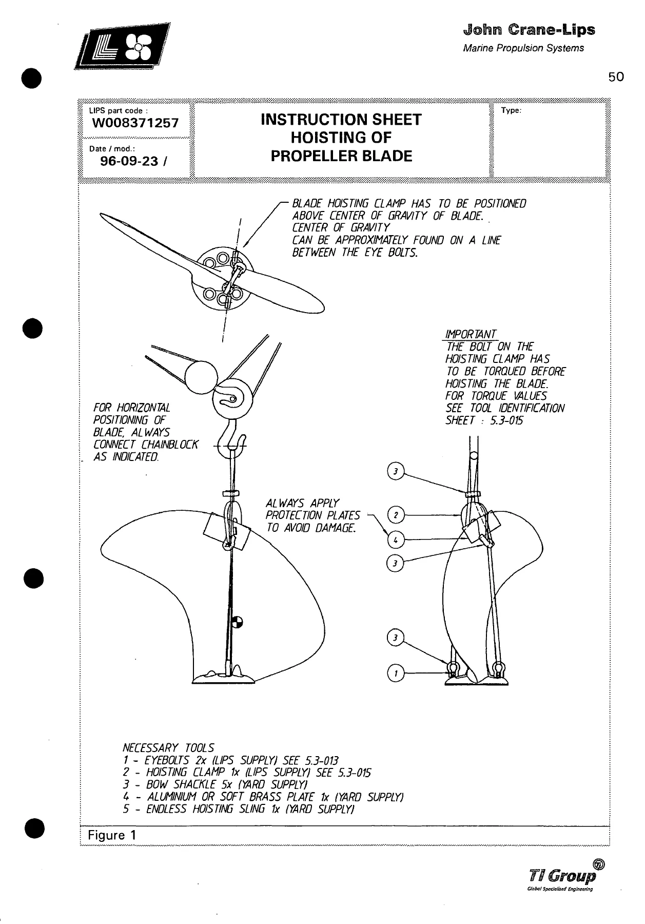
This John Crane-Lips Controllable Pitch Propeller Installation Instruction Handbook Part 1 is the definitive reference for the LIPS controllable pitch propeller system aboard the Sietas Typ 167 bulk carrier. It walks you through the complete shaft line assembly sequence, including hydraulic flange coupling mounting and demounting, propeller blade mounting and demounting, and pitch adjustment procedures. The hydraulic system chapter provides detailed instructions for filling, flushing, draining, and oil sampling, along with operational checks for pitch adjusting time, safety valve settings, and pump switch-over systems. The maintenance chapter covers inspection intervals, adjustment data, faultfinding, and remedies for common system malfunctions.
Key Systems and Components Covered
- Propeller: 4-blade controllable pitch propeller, 4800 mm diameter, NiAl bronze blades and hub, C-type hub
- Shaft Line: Propeller shaft 9051 mm length, 404/360 mm diameter, C45E material, with moving oil pipes and blocking valve
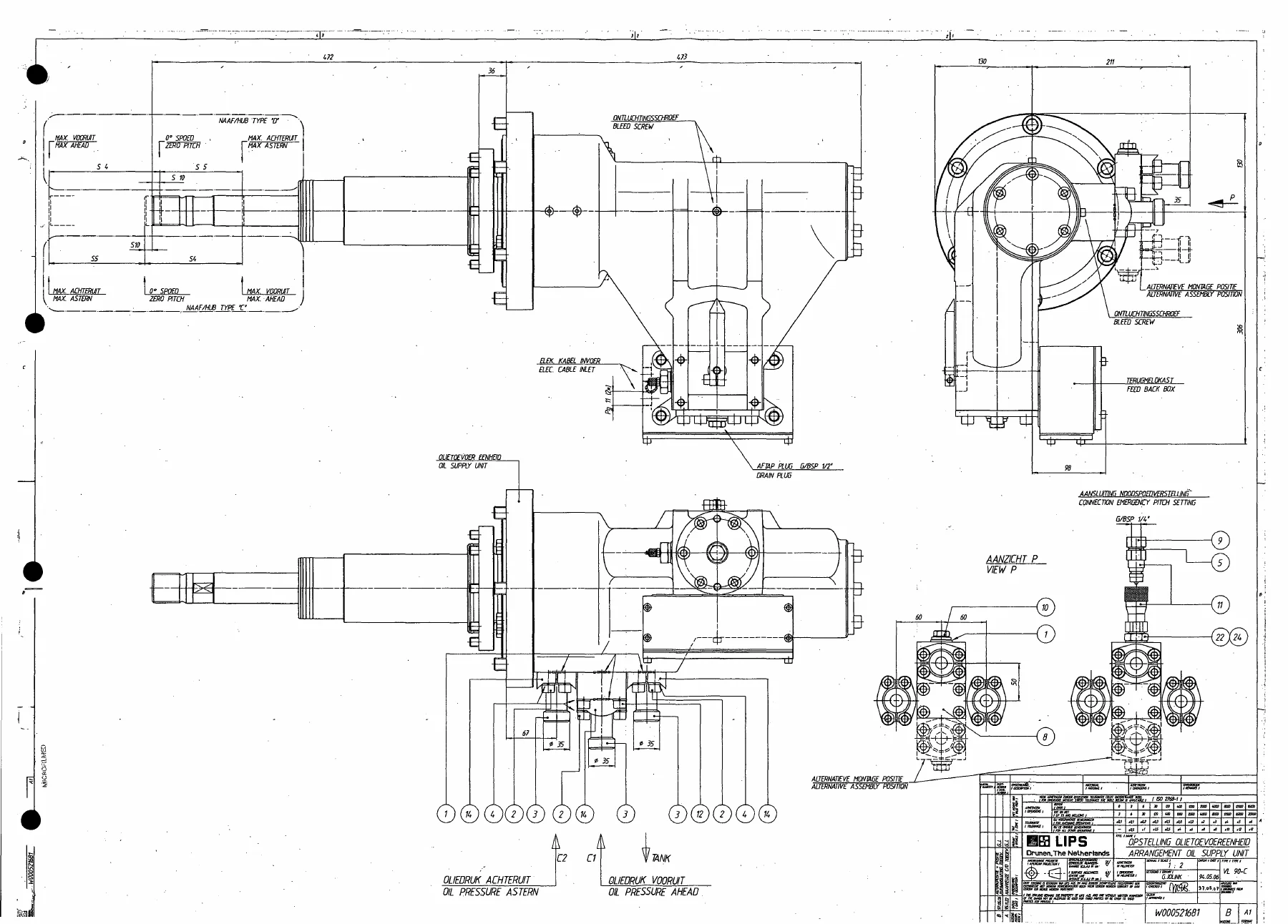
- Pitch Servo Unit: Type VL 90-C oil distribution box, guide bush, transmitter box, emergency pitch setting connection
- Hydraulic Power Equipment: Power pack with 400 dm³ tank, two electrically driven pumpsets, oil cooler, proportional valve, load sensing system, hub pressure pump
- Control System: Pitch control valve, pressure switches, alarm signals, emergency pitch setting procedure
The John Crane-Lips Controllable Pitch Propeller Installation Instruction Handbook Part 1 also includes comprehensive technical data including pitch values, hydraulic system pressures and capacities, oil types, torque specifications, and alignment procedures using the Gap and Sag method. Emergency pitch setting procedures are covered in detail for situations where hydraulic power is lost or the control system fails, allowing the propeller to be locked in a suitable ahead position for continued operation.
Why This Manual Matters
Working on a controllable pitch propeller system without the correct procedures and specifications can lead to equipment damage, operational hazards, and costly downtime. This John Crane-Lips Controllable Pitch Propeller Installation Instruction Handbook Part 1 ensures that every step of assembly, commissioning, and maintenance is carried out correctly according to the manufacturer’s instructions. From hydraulic coupling drive-up measurements to blade bolt tightening torques and hydraulic system flushing requirements, the manual provides the exact figures and sequences needed for safe and effective work.
IMAGES PREVIEW
Upon purchase, you receive an instant PDF download of the John Crane-Lips Controllable Pitch Propeller Installation Instruction Handbook Part 1 that can be viewed on any device, printed for use in the workshop or engine room, and kept as a permanent reference for the life of the vessel.

Reviews
There are no reviews yet.