
John Crane-Lips FT300 Transverse Thruster Mechanical Manual – Maintenance & Service PDF
Original price was: $39.95.$24.95Current price is: $24.95.
The complete John Crane-Lips FT300 Transverse Thruster Mechanical Manual (LIPS order B02363) covering propeller, lower gearbox, structure, lubrication and shaft brake procedures, with bearing clearance, gear pattern and backlash adjustment data.
Description
John Crane-Lips FT300 Transverse Thruster Mechanical Manual
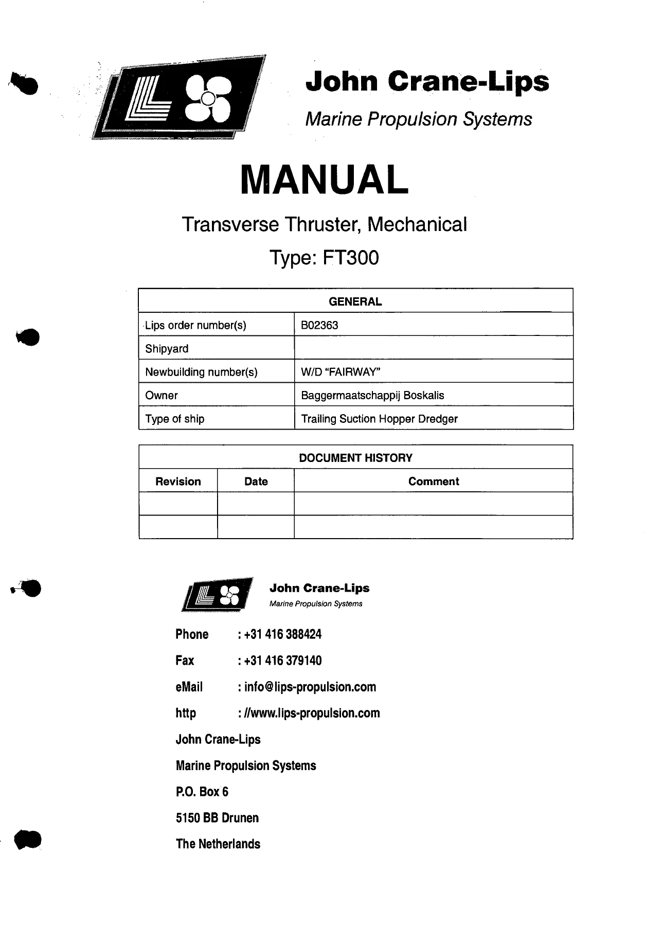
The John Crane-Lips FT300 Transverse Thruster Mechanical Manual is the full mechanical maintenance publication for the FT300 tunnel thruster, issued under LIPS order number B02363 for the trailing suction hopper dredger W/D “FAIRWAY” owned by Baggermaatschappij Boskalis, and dated 2002-02-01. Across roughly 318 pages it documents the propulsion system, transmission system, structure, lubrication system and auxiliary shaft brake, with step-by-step removal, disassembly, assembly, installation and change procedures backed by warnings, cautions, required conditions, support equipment lists and consumables. If you maintain, repair or overhaul an FT300 transverse thruster, this is the reference document that shows how the mechanical side of the unit is built and how to take it apart without damaging it.
File Details
- Manual type: Mechanical Maintenance Manual
- Brand: John Crane-Lips Marine Propulsion Systems
- Model: Transverse Thruster, Type FT300
- LIPS order number: B02363
- Shipyard newbuilding: W/D “FAIRWAY”
- Owner: Baggermaatschappij Boskalis
- Vessel type: Trailing Suction Hopper Dredger
- Language: English
- Page count: Approx. 318 pages
- File format: PDF
- Date: 2002-02-01
Chapters Covered
- Chapter 00 – Front Matter: Introduction, Warnings and Cautions, Symbols, Abbreviations, Classification and Technical Data
- Chapter 01 – General: System Description, Component Location, Scheduled Inspections, Removal Procedures, Disassembly Procedures, Assembly Procedures, Installation Procedures, Change Procedures
- Chapter 02 – Propulsion System: Description, Propeller Removal, Propeller Installation
- Chapter 03 – Transmission System: Description, Gear System Description, Lower Gearbox Description, Lower Gearbox Gearset Adjustment/Test, Lower Gearbox Removal, Disassembly, Assembly and Installation, Propeller Shaft Disassembly/Assembly, Input Shaft Disassembly/Assembly, Propeller Shaft Seal and Oil Seals Change, Flexible Shaft Coupling Removal/Installation
- Chapter 05 – Structure: Description, Outer Rope Guard Assembly Removal/Installation, Tunnel Assembly Removal/Installation, Sacrificial Anodes Change
- Chapter 08 – Lubrication System: Description, Filling, Draining, Flushing, Oil-Pressure Filter Cartridge Change
- Chapter 09 – Auxiliary Systems: Description, Shaft Brake Description, Shaft Brake Pad Change
- Appendix: Drawing list, parts lists and cross-reference, Loctite product information, torque manual, flexible coupling instructions, Safeset ST-B 180 instructions, hydraulic pump, pressure filter, pressure switch and pneumatic valve data, Hempel coating specifications
The manual is organised as a set of data modules, each carrying a Data Module Code (DMC) that identifies its position in the system hierarchy and its location code – whether the ship is afloat, in dry dock, or the component is in the workshop. That structure lets a technician jump straight to the exact procedure for the job at hand rather than reading the whole document. Chapter 04 (Pitch Control System), Chapter 06 (Steering System) and Chapter 07 (Hydraulic Power System) are marked as not applicable to the FT300, so the mechanical content stays focused on the systems the thruster actually uses.
What the FT300 Manual Covers in Practice
The propulsion chapter deals with the propeller itself – the four-blade Cunial monobloc hub, the taper interference fit on the propeller shaft, and the adjusting plate that seals the shaft end and stops the propeller springing off after installation. The propeller removal and installation procedures are written around a high-pressure oil pump, a hydraulic nut and the plug holes in the propeller hub, with the start-point load and maximum pressure values taken from the Propeller Mounting drawing.
The transmission chapter is the largest part of the manual. It opens with the gear system and the lower gearbox, then works through the Klingelnberg HPG cyclo-palloid gearset, the input and propeller shafts, the roller bearing arrangements, and the adjusting rings that set bearing clearance, gear pattern and gear backlash. Separate procedures cover lower gearbox removal, disassembly, assembly and installation, plus dedicated disassembly and assembly sequences for the propeller shaft and the input shaft. The oil seal change on the propeller shaft seal is covered too, along with the flexible shaft coupling and its intermediate shaft.
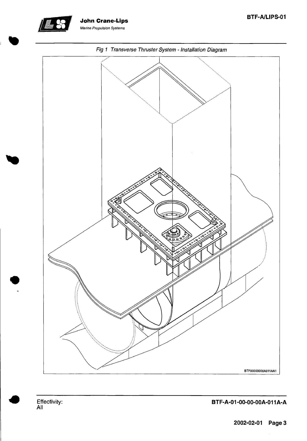
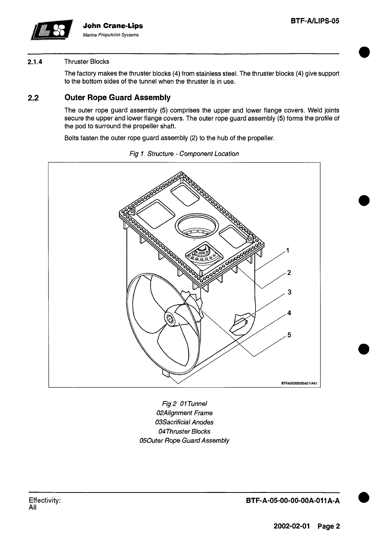
Structure procedures explain the tunnel assembly, the alignment frame, the outer rope guard assembly and the sacrificial anodes. The lubrication chapter describes the header tank, the lubrication pump set and the valve settings for normal operation, filling, draining and flushing the lower gearbox. The auxiliary chapter covers the shaft brake – the disc-brake caliper, the pad assemblies and the brake control panel.
Adjustment, Test and Measurement Data
One of the most valuable parts of this FT300 manual is the lower gearbox gearset adjustment and test procedure. It walks through measuring input shaft and propeller shaft bearing clearances with a dial gauge and chain hoist, machining the adjusting rings to the correct thickness, checking the gear pattern with dye paste, and measuring gear backlash with a dial gauge on a magnetic support. The manual includes the axial clearance tables for each pod type, the temperature compensation values for the input shaft adapter ring, and the gearset backlash tolerances for each pinion and crown wheel tooth count.
Flexible Shaft Coupling and Torque Protection
The flexible shaft coupling connects the torque protection device to the input shaft of the lower gearbox, and the manual covers its removal and installation in detail – upper and lower hubs, spacer, brake disc, intermediate shaft and the torque values for the coupling screws. The appendix includes the Rexnord BSD Thomas coupling installation, service and maintenance instructions, plus the Voith Safeset ST-B 180 torque-limiting coupling instruction with its assembly, lubrication, pressure setting and calibration diagram details.
Technical Data Included
The classification and technical data section gives the FT300’s headline figures, including the tunnel inside diameter of 2895 mm and length of 2581 mm, the 2850 mm propeller running at 223 rpm with four blades, the lower gearbox gear ratio of 750:223 and gear module of 15.5, the lubrication oil system with a 10 litre/min pump at 0.5 bar operating pressure, and the propeller drive motor rated at 2650 kW and 750 rpm. Mass figures are given for the thruster without drive motor, the tunnel, the cover, the propeller and the lower gearbox.
Safety and Consumables
Every procedure is preceded by the warnings and cautions that apply, covering pressurised oil, lifting equipment, welding earth connections, rotating components and the specific hazards of removing a propeller with a high-pressure oil pump. Consumable lists name the Loctite products, Molykote greases, O-rings, sealing rings and cleaning agents the job requires, with part numbers where the manual gives them. A separate Loctite information sheet and a torque manual with metric thread torque values and locking compound symbols are included in the appendix.
Reference Drawings and Parts Lists
The appendix lists the drawings used during manufacture – arrangement of the transverse thruster, arrangement flex coupling, lubrication oil connections, propeller and mounting, assembly of the pod, thruster seal, lubrication oil diagram, lubrication pump set, brake control panel, arrangement shaft brake, cover and coating specifications. A part-number-to-part-list cross-reference lets you find the location of a specific part number for maintenance, repair and overhaul, and the pod assembly parts list runs through the gearset, bearings, seals, housings and fasteners with article numbers and quantities.
Who This Manual Is For
This is a workshop-level document for marine engineers, shipyard fitters and maintenance technicians responsible for the FT300 transverse thruster. It assumes access to the lower gearbox, the tunnel and the propeller, and it tells you which procedures need the vessel afloat, which need dry dock, and which can be done with the component on the bench. The level of detail – down to torque values, bearing clearances, gear backlash tolerances and adjusting ring machining – makes it suitable for both scheduled maintenance and full overhaul.
Get the FT300 Transverse Thruster Manual as an Instant PDF
IMAGES PREVIEW
With the John Crane-Lips FT300 Transverse Thruster Mechanical Manual on hand you can carry out scheduled inspections, remove and refit the propeller, strip and rebuild the lower gearbox, reset bearing clearance, gear pattern and backlash, change the propeller shaft oil seals, service the lubrication system and replace the shaft brake pads – all using the procedures, tolerances and torque figures the manufacturer set out. Getting the bearing clearances, gear pattern and backlash right is what keeps the gearset and bearings alive, and the manual gives you the tables and measurement methods to do it. Delivered as an instant PDF download after payment, no shipping and no waiting, readable on a laptop, tablet or phone and printable for the workshop so the pages you need are next to the machine.

Reviews
There are no reviews yet.