★ TRUSTED BY 321,897+ PROFESSIONALS WORLDWIDE
🏒
Trusted Business
Verified & Licensed
πŸ›‘οΈ
Virus Free Files
100% Safe Downloads
πŸ”’
Secure Payment
SSL Protected
⚑
Instant Delivery
Available Immediately
Sale!

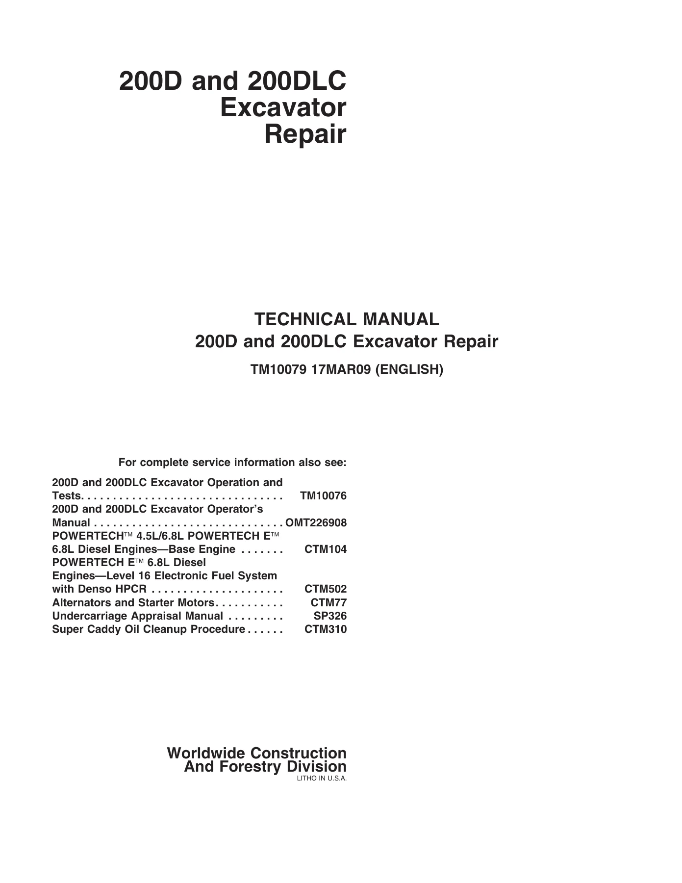
John Deere 200D and 200DLC Excavator Repair Technical Manual TM10079

Original price was: $39.95.Current price is: $23.95.

Complete John Deere 200D and 200DLC Excavator Repair Technical Manual TM10079 in PDF. Covers tracks, engine, hydraulics, swing system, operator’s station, travel gearbox, and more – the full factory repair reference for these excavators.

⚑
Instant PDF Download
Available immediately
πŸ’Ύ
Save to Your Device
Download & keep forever
πŸ›‘οΈ
Antivirus Scanned
100% virus-free
🌍
Trusted Worldwide
175,000+ customers

Description

John Deere 200D and 200DLC Excavator Repair Technical Manual TM10079

This is the full John Deere 200D and 200DLC Excavator Repair Technical Manual TM10079, the repair half of the factory technical documentation set for these tracked excavators. It is the book you reach for when a component has to come off, be disassembled, inspected against tolerance, resealed, and put back together to John Deere’s procedures. From track rollers and recoil springs to the hydraulic pumps, swing gearbox, travel motor, and the operator’s station, TM10079 walks a technician through removal, teardown, reassembly, and torque specs with diagrams and photographic step-by-step callouts.

File Details

  • Manual type: Repair Technical Manual (component repair and overhaul)
  • Brand / Manufacturer: John Deere (Deere & Company, Moline, Illinois)
  • Models covered: 200D Excavator, 200DLC Excavator
  • Document number: TM10079
  • Edition / Date: 17MAR09 (English)
  • Language: English
  • Format: PDF (instant digital download)
  • Approximate length: Around 400 pages across 11 sections
  • Companion reference: TM10076 (Operation and Tests), OMT226908 (Operator’s Manual)

Chapters Covered in This 200D and 200DLC Excavator Repair Technical Manual

The manual is organised into groups, each prefaced by its own summary of essential tools, service equipment, service parts kits, specifications, wear tolerances and torque values. Top-level contents:

  • Section 00 – General Information: Safety; Torque Values (metric and unified inch bolts, O-ring boss fittings, 37Β° flare and 30Β° cone seat connectors, flat face O-ring seals, four bolt flange fittings)
  • Section 01 – Tracks: Track Roller remove / disassemble / pressure test; Carrier Roller; Metal Face Seals repair; Track Shoe; Track Chain remove / disassemble / repair; Sprocket; Front Idler remove, disassemble and assemble; Track Adjuster and Recoil Spring; Track Adjuster Cylinder
  • Section 02 – Axles, Differentials and Suspension Systems: Travel Gearbox remove and disassemble; Travel Motor and Park Brake; Counterbalance Valve; Crossover Relief Valve; Make-Up Check Valve; Travel Speed Selector Valve; Travel Motor and Park Brake Start-Up
  • Section 04 – Engine: Engine Removal and Installation
  • Section 05 – Engine Auxiliary System: Cooling System (radiator, hydraulic oil cooler, intercooler, fuel cooler, cooling package, fan, fan guard, fan shroud, coolant surge tank); Intake System (air cleaner); External Fuel Supply System (fuel tank, primary fuel filter / water separator, final fuel filter)
  • Section 07 – Dampener Drive (Flex Coupling): Flex coupling removal and installation
  • Section 17 – Frame or Supporting Structure: Frame installation; chassis counterweight removal and installation; welding repair of major structure
  • Section 18 – Operator’s Station: Cab removal and installation; sliding windows and windowpanes; seat and seat belt; heating and air conditioning (compressor, condenser, receiver-dryer, refrigerant recovery and charging)
  • Section 33 – Excavator: Bucket remove and install and bucket pin-up data; front attachment frames (bucket links, arm, boom, pin and bushing inspection); Hydraulic System (pump 1 and 2, regulators, pilot pump, pilot pressure regulating valve, pilot shutoff solenoid, fan drive pump and motor, control valve 5-spool and 4-spool, hydraulic oil tank, boom / arm / bucket cylinders, hydraulic cylinder bleed)
  • Section 43 – Swing or Pivoting System: Swing gearbox remove and disassemble; swing gearbox start-up; upperstructure removal; swing bearing removal, disassembly and seal installation; Center Joint remove, disassemble and air test; swing motor and park brake remove, disassemble, inspection and assembly; crossover relief valve and make-up check valve; swing park brake release valve
  • Section 99 – Dealer Fabricated Tools: Drawings and material requirements for DF1063 Lift Bracket, ST4920 Track Recoil Spring tool, DFT1087 Guard, DFT1110 Spacer, DFT1130 Adapter, DFT1036A Travel Gearbox Nut Wrench, DF1038 Torque Adapter, DFT1109 Holding Bar, Center Joint Lifting Tool, DFT1144 Guide Pin, DFT1119 Pump Support, DFT1220 Swing Gearbox Nut Spanner Wrench

What the John Deere 200D and 200DLC Excavator Repair Technical Manual Gives You

TM10079 is written for the experienced technician. It does not waste space on basic theory – that is covered in companion publications – and instead concentrates on how a specific component on the 200D or 200DLC comes apart, what to measure while it is open, and how it goes back together. Each group starts with a listing of the essential tools, service equipment, service parts kits, specifications, wear tolerances, and torque values that apply to that job, so you can lay out everything you need before you start pulling bolts. Exploded-view illustrations and photographic sequences call out fasteners, O-rings, metal face seals, snap rings, spacers and shims by number so the correct order and orientation are unambiguous. Where a measurement determines whether a part can be reused – front idler flange height, three bar grouser height, metal face seal wear pattern, pump drive gear backlash, servo piston clearance, slipper thickness, friction plate thickness, cylinder rod curvature – the value is given on the spot.

Complete PDF Bookmark Tree

Complete Bookmarks

The complete bookmarks in the β€œJohn Deere 200D and 200DLC Excavator Repair Technical Manual TM10079” are as follows:

Contentsp. 5
General Informationp. 9
Safetyp. 11
Recognize Safety Informationp. 11
Follow Safety Instructionsp. 11
Operate Only If Qualifiedp. 11
Wear Protective Equipmentp. 12
Avoid Unauthorized Machine Modificationsp. 12
Add Cab Guarding for Special Usesp. 13
Inspect Machinep. 13
Stay Clear of Moving Partsp. 13
Avoid High-Pressure Fluidsp. 14
Avoid High-Pressure Oilsp. 14
Beware of Exhaust Fumesp. 15
Prevent Firesp. 15
Prevent Battery Explosionsp. 15
Handle Chemical Products Safelyp. 16
Dispose of Waste Properlyp. 16
Prepare for Emergenciesp. 16
Use Steps and Handholds Correctlyp. 17
Start Only From Operator's Seatp. 17
Use and Maintain Seat Beltp. 17
Prevent Unintended Machine Movementp. 18
Avoid Work Site Hazardsp. 19
Keep Riders Off Machinep. 19
Avoid Backover Accidentsp. 20
Avoid Machine Tip Overp. 20
Use Special Care When Lifting Objectsp. 21
Add and Operate Attachments Safelyp. 21
Park and Prepare for Service Safelyp. 22
Service Cooling System Safelyp. 22
Remove Paint Before Welding or Heatingp. 23
Make Welding Repairs Safelyp. 24
Drive Metal Pins Safelyp. 24
Torque Valuesp. 25
Torque Valuep. 25
Metric Bolt and Cap Screwp. 25
Additional Metric Cap Screw Torque Valuesp. 26
Torque Valuep. 28
Unified Inch Bolt and Cap Screwp. 28
Service Recommendations for 37Β° Flare and 30Β° Cone Seat Connectorsp. 29
Service Recommendations for O-Ring Boss Fittingsp. 30
Service Recommendationp. 32
O-Ring Boss Fittings In Aluminum HousingExcavatorsp. 32
Service Recommendations For Flared Connectionsβ€”Straight or Tapered Threadsp. 34
Service Recommendations For Flat Face O-Ring Seal Fittingsp. 35
Service Recommendationp. 36
O-Ring Face Seal Fittings with SAE Inch Hex Nut and Stud End for High Pressurep. 36
O-Ring Face Seal Fittings with Metric Hex Nut and Stud End for Standard Pressurep. 38
O-Ring Face Seal Fittings with Metric Hex Nut and Stud End for High Pressurep. 40
Service Recommendations for Metric Series Four Bolt Flange Fittingp. 42
Service Recommendations For Inch Series Four Bolt Flange Fittingsp. 43
Inch Series Four Bolt Flange Fitting For High Pressure Service Recommendationsp. 44
Tracksp. 45
Track Systemp. 47
Track Roller Remove and Installp. 47
Track Roller Disassemble and Assemblep. 49
Track Roller Pressure Testp. 51
Track Carrier Roller Remove and Installp. 52
Metal Face Seals Repairp. 54
Track Shoe Remove and Installp. 57
Track Chain Remove and Installp. 58
Track Chain Disassemble and Assemblep. 62
Track Chain Repairp. 63
Sprocket Remove and Installp. 65
Front Idler Remove and Installp. 66
Front Idler Disassemble and Assemblep. 67
Track Adjuster and Recoil Spring Remove and Installp. 69
Track Adjuster and Recoil Spring Disassemble and Assemblep. 71
Track Adjuster Cylinder Disassemble and Assemblep. 76
Axles, Differentials and Suspension Systemsp. 79
Axle Shaft, Bearings, and Reduction Gearsp. 81
Travel Gearbox Remove and Installp. 81
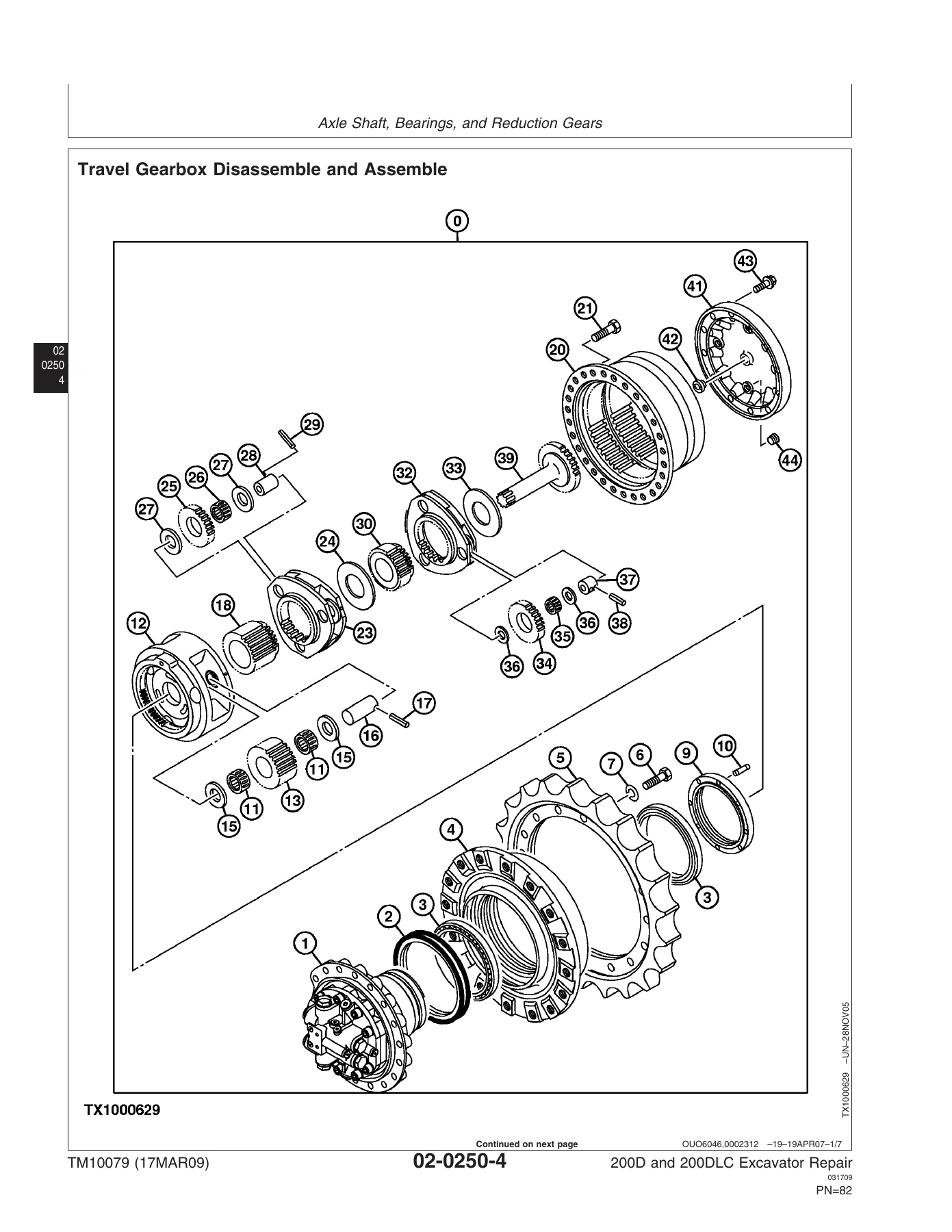
Travel Gearbox Disassemble and Assemblep. 84
Hydraulic Systemp. 92
Travel Motor and Park Brake Remove and Installp. 92
Travel Motor and Park Brake Disassemble and Assemblep. 100
Counterbalance Valve Remove and Installp. 103
Crossover Relief Valve Remove and Installp. 105
Make-Up Check Valve Remove and Installp. 107
Travel Speed Selector Valve Remove and Installp. 109
Travel Motor and Park Brake Start-Up Procedurep. 111
Enginep. 113
Removal and Installationp. 115
Engine Remove and Installp. 115
Engine Auxiliary Systemp. 125
Cooling Systemp. 127
Radiator Remove and Installp. 127
Hydraulic Oil Cooler Remove and Installp. 131
Intercooler Remove and Installp. 133
Fuel Cooler Remove and Installp. 138
Cooling Package Remove and Installp. 138
Fan, Fan Guard, and Fan Shroud Remove and Installp. 145
Coolant Surge Tank Remove and Installp. 149
Intake Systemp. 152
Air Cleaner Remove and Installp. 152
External Fuel Supply Systemp. 155
Fuel Tank Remove and Installp. 155
Primary Fuel Filter (Water Separator) Remove and Installp. 157
Final Fuel Filter Remove and Installp. 158
Dampener Drive (Flex Coupling)p. 159
Elementsp. 161
Dampener Drive (Flex Coupling) Remove and Installp. 161
Frame or Supporting Structurep. 163
Frame Installationp. 165
Welding On Machinep. 165
Welding Repair of Major Structurep. 167
Chassis Weightsp. 169
Counterweight Remove and Installp. 169
Operator's Stationp. 171
Removal and Installationp. 173
Cab Remove and Installp. 173
Operator Enclosurep. 179
Sliding Windows Remove and Installp. 179
Windowpanes Remove and Installp. 180
Windowpanes Dimensionsp. 181
Seat and Seat Beltp. 187
Seat Remove and Installp. 187
Seat Belt Remove and Installp. 188
Mechanical Suspension Seat Disassemble and Assemblep. 189
Air Suspension Seat Disassemble and Assemblep. 190
Left and Right Console Covers Remove and Installp. 191
Heating and Air Conditioningp. 195
Refrigerant Cautions and Proper Handlingp. 195
Flush and Purge Air Conditioner Systemp. 197
R134a Refrigerant Oil Informationp. 200
R134a Refrigerant Recovery/Recycling and Charging Station Installation Procedurep. 201
Recover R134a Refrigerantp. 202
Evacuate R134a Systemp. 203
Charge R134a Systemp. 204
Compressor Remove and Installp. 205
Condenser Remove and Installp. 205
Heater and Air Conditioner Remove and Installp. 207
Receiver-Dryer Remove and Installp. 211
Excavatorp. 213
Bucketsp. 215
Bucket Remove and Installp. 215
Bucket Pin-Up Datap. 216
Framesp. 219
Bucket Links Remove and Installp. 219
Arm Remove and Installp. 220
Boom Remove and Installp. 224
Inspect Pins, Bushings and Bossesβ€”Front Attachmentp. 229
Bushings and Seal Remove and Installp. 232
Hydraulic Systemp. 233
Apply Vacuum to Hydraulic Oil Tankp. 233
Hydraulic Oil Cleanup Procedure Using Portable Filter Caddyp. 235
Pump 1 and 2 Remove and Installp. 236
Pump 1 and 2 Disassemble and Assemblep. 242
Pump 1 and 2 Inspectionp. 254
Pump 1 and 2 Start-Up Procedurep. 257
Pump 1 and 2 Regulator Remove and Installp. 258
Pump 1 and 2 Regulator Disassemble and Assemblep. 260
Pilot Pump Remove and Installp. 262
Pilot Pump Disassemble and Assemblep. 264
Pilot Pump Drive Shaft Remove and Installp. 266
Pilot Pressure Regulating Valve and Filter Remove and Installp. 267
Pilot Pressure Regulating Valve and Filter Disassemble and Assemblep. 268
Pilot Shutoff Solenoid Valve Remove and Installp. 268
Pilot Shutoff Solenoid Valve Disassemble and Assemblep. 270
Fan Drive Pump Remove and Installp. 271
Fan Drive Motor Remove and Installp. 272
Fan Drive Control Valve Remove and Installp. 275
Solenoid Valve Manifold Remove and Installp. 277
Solenoid Valve Remove and Installβ€”Power Dig (SG), Travel Speed (SI), Boom Mode (SC), and Boom Flow Rate (SF)p. 279
Pilot Valve (Left and Right) Remove and Installp. 280
Pilot Valve (Left and Right) Disassemble and Assemblep. 284
Travel Pilot Valve Remove and Installp. 286
Travel Pilot Valve Disassemble and Assemblep. 288
Pilot Signal Manifold Remove and Installp. 290
Pilot Signal Manifold Disassemble and Assemblep. 292
Control Valve Remove and Installp. 295
Control Valve (5-Spool) Disassemble and Assemblep. 297
Control Valve (4-Spool) Disassemble and Assemblep. 305
Hydraulic Oil Tank Remove and Installp. 311
Hydraulic Oil Tank Disassemble and Assemblep. 314
Restriction Valve Remove and Installp. 315
Hydraulic Oil Cooler Bypass Valve Remove and Installp. 317
Boom Cylinder Remove and Installp. 319
Boom Cylinder Disassemble and Assemblep. 323
Arm Cylinder Remove and Installp. 325
Arm Cylinder Disassemble and Assemblep. 330
Bucket Cylinder Remove and Installp. 333
Bucket Cylinder Disassemble and Assemblep. 337
Hydraulic Cylinder Bleed Procedurep. 340
Swing or Pivoting Systemp. 341
Mechanical Drive Elementsp. 343
Swing Gearbox Remove and Installp. 343
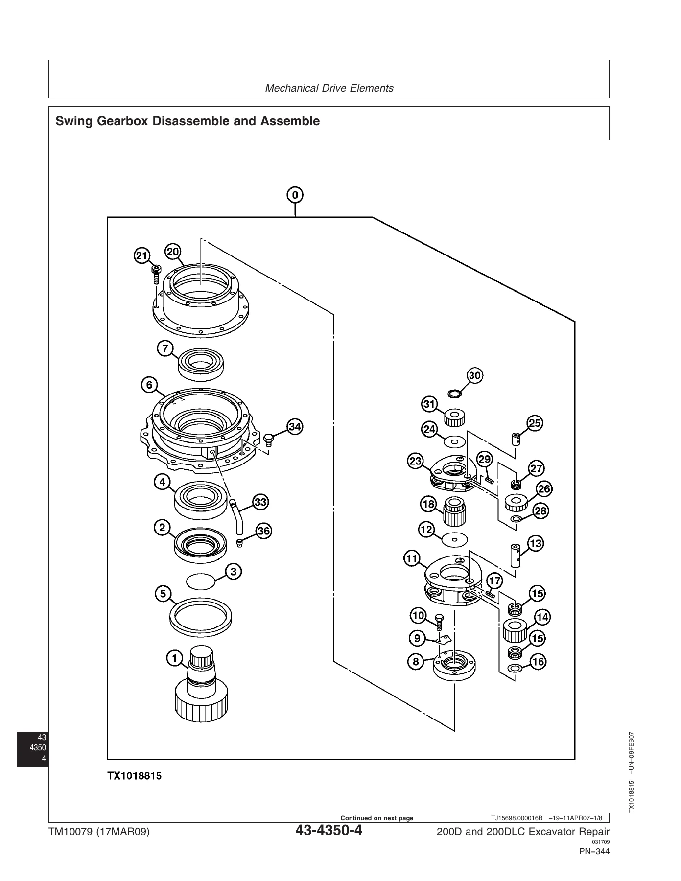
Swing Gearbox Disassemble and Assemblep. 346
Swing Gearbox Start-Up Procedurep. 353
Upperstructure Remove And Installp. 353
Swing Bearing Remove and Installp. 356
Swing Bearing Disassemble and Assemblep. 358
Swing Bearing Upper Seal Installp. 361
Swing Bearing Lower Seal Installp. 361
Hydraulic Systemp. 363
Center Joint Remove and Installp. 363
Center Joint Disassemble and Assemblep. 366
Center Joint Air Testp. 367
Swing Motor and Park Brake Remove and Installp. 368
Swing Motor and Park Brake Disassemblep. 372
Swing Motor and Park Brake Inspectionp. 374
Swing Motor and Park Brake Assemblep. 376
Swing Motor and Park Brake Start-Up Procedurep. 378
Crossover Relief Valve and Make-Up Check Valve Remove and Installp. 379
Make-Up Check Valve Disassemble and Assemblep. 380
Swing Park Brake Release Valve Remove and Installp. 381
Dealer Fabricated Toolsp. 383
Dealer Fabricated Toolsp. 385
DF1063 Lift Bracketp. 385
ST4920 Track Recoil Spring Disassembly and Assembly Toolp. 387
DFT1087 Track Recoil Spring Disassembly and Assembly Guard Toolp. 391
DFT1110 Spacerp. 392
DFT1130 Adapterp. 393
DFT1036A Travel Gearbox Nut Wrenchp. 394
DF1038 Torque Adapterp. 395
DFT1109 Holding Barp. 396
Center Joint (Rotary Manifold) Lifting Toolp. 397
DFT1144 Guide Pinp. 397
DFT1119 Pump Supportp. 398
DFT1220 Swing Gearbox Nut Spanner Wrenchp. 400
Page Numbersp. 5
Section 00p. 9
Group 01p. 11
1p. 11
2p. 12
3p. 13
4p. 14
5p. 15
6p. 16
7p. 17
8p. 18
9p. 19
10p. 20
11p. 21
12p. 22
13p. 23
14p. 24
Group 0003p. 25
1p. 25
2p. 26
3p. 27
4p. 28
5p. 29
6p. 30
7p. 31
8p. 32
9p. 33
10p. 34
11p. 35
12p. 36
13p. 37
14p. 38
15p. 39
16p. 40
17p. 41
18p. 42
19p. 43
20p. 44
21p. 45
22p. 46
Section 01p. 45
Group 0130p. 47
1p. 47
2p. 48
3p. 49
4p. 50
5p. 51
6p. 52
7p. 53
8p. 54
9p. 55
10p. 56
11p. 57
12p. 58
13p. 59
14p. 60
15p. 61
16p. 62
17p. 63
18p. 64
19p. 65
20p. 66
21p. 67
22p. 68
23p. 69
24p. 70
25p. 71
26p. 72
27p. 73
28p. 74
29p. 75
30p. 76
31p. 77
32p. 78
33p. 79
34p. 80
Section 02p. 79
Group 0250p. 81
1p. 81
2p. 82
3p. 83
4p. 84
5p. 85
6p. 86
7p. 87
8p. 88
9p. 89
10p. 90
Group 0260p. 92
1p. 91
2p. 92
3p. 93
4p. 94
5p. 95
6p. 96
7p. 97
8p. 98
9p. 99
10p. 100
11p. 101
12p. 102
13p. 103
14p. 104
15p. 105
16p. 106
17p. 107
18p. 108
19p. 109
20p. 110
21p. 111
22p. 112
23p. 113
24p. 114
Section 04p. 113
Group 0400p. 115
1p. 115
2p. 116
3p. 117
4p. 118
5p. 119
6p. 120
7p. 121
8p. 122
9p. 123
10p. 124
11p. 125
12p. 126
Section 05p. 125
Group 0510p. 127
1p. 127
2p. 128
3p. 129
4p. 130
5p. 131
6p. 132
7p. 133
8p. 134
9p. 135
10p. 136
11p. 137
12p. 138
13p. 139
14p. 140
15p. 141
16p. 142
17p. 143
18p. 144
19p. 145
20p. 146
21p. 147
22p. 148
23p. 149
24p. 150
Group 0520p. 152
1p. 151
2p. 152
3p. 153
4p. 154
Group 0560p. 155
1p. 155
2p. 156
3p. 157
4p. 158
5p. 159
6p. 160
Section 07p. 159
Group 0752p. 161
1p. 161
2p. 162
3p. 163
4p. 164
Section 17p. 163
Group 1740p. 165
1p. 165
2p. 166
3p. 167
4p. 168
Group 1749p. 169
1p. 169
2p. 170
3p. 171
4p. 172
Section 18p. 171
Group 1800p. 173
1p. 173
2p. 174
3p. 175
4p. 176
5p. 177
6p. 178
Group 1810p. 179
1p. 179
2p. 180
3p. 181
4p. 182
5p. 183
6p. 184
7p. 185
8p. 186
Group 1821p. 187
1p. 187
2p. 188
3p. 189
4p. 190
5p. 191
6p. 192
7p. 193
8p. 194
Group 1830p. 195
1p. 195
2p. 196
3p. 197
4p. 198
5p. 199
6p. 200
7p. 201
8p. 202
9p. 203
10p. 204
11p. 205
12p. 206
13p. 207
14p. 208
15p. 209
16p. 210
17p. 211
18p. 212
19p. 213
20p. 214
Section 33p. 213
Group 3302p. 215
1p. 215
2p. 216
3p. 217
4p. 218
Group 3340p. 219
1p. 219
2p. 220
3p. 221
4p. 222
5p. 223
6p. 224
7p. 225
8p. 226
9p. 227
10p. 228
11p. 229
12p. 230
13p. 231
14p. 232
Group 3360p. 233
1p. 233
2p. 234
3p. 235
4p. 236
5p. 237
6p. 238
7p. 239
8p. 240
9p. 241
10p. 242
11p. 243
12p. 244
13p. 245
14p. 246
15p. 247
16p. 248
17p. 249
18p. 250
19p. 251
20p. 252
21p. 253
22p. 254
23p. 255
24p. 256
25p. 257
26p. 258
27p. 259
28p. 260
29p. 261
30p. 262
31p. 263
32p. 264
33p. 265
34p. 266
35p. 267
36p. 268
37p. 269
38p. 270
39p. 271
40p. 272
41p. 273
42p. 274
43p. 275
44p. 276
45p. 277
46p. 278
47p. 279
48p. 280
49p. 281
50p. 282
51p. 283
52p. 284
53p. 285
54p. 286
55p. 287
56p. 288
57p. 289
58p. 290
59p. 291
60p. 292
61p. 293
62p. 294
63p. 295
64p. 296
65p. 297
66p. 298
67p. 299
68p. 300
69p. 301
70p. 302
71p. 303
72p. 304
73p. 305
74p. 306
75p. 307
76p. 308
77p. 309
78p. 310
79p. 311
80p. 312
81p. 313
82p. 314
83p. 315
84p. 316
85p. 317
86p. 318
87p. 319
88p. 320
89p. 321
90p. 322
91p. 323
92p. 324
93p. 325
94p. 326
95p. 327
96p. 328
97p. 329
98p. 330
99p. 331
100p. 332
101p. 333
102p. 334
103p. 335
104p. 336
105p. 337
106p. 338
107p. 339
108p. 340
109p. 341
110p. 342
Section 43p. 341
Group 4350p. 343
1p. 343
2p. 344
3p. 345
4p. 346
5p. 347
6p. 348
7p. 349
8p. 350
9p. 351
10p. 352
11p. 353
12p. 354
13p. 355
14p. 356
15p. 357
16p. 358
17p. 359
18p. 360
19p. 361
20p. 362
Group 4360p. 363
1p. 363
2p. 364
3p. 365
4p. 366
5p. 367
6p. 368
7p. 369
8p. 370
9p. 371
10p. 372
11p. 373
12p. 374
13p. 375
14p. 376
15p. 377
16p. 378
17p. 379
18p. 380
19p. 381
20p. 382
21p. 383
22p. 384
Section 99p. 383
Group 9900p. 385
1p. 385
2p. 386
3p. 387
4p. 388
5p. 389
6p. 390
7p. 391
8p. 392
9p. 393
10p. 394
11p. 395
12p. 396
13p. 397
14p. 398
15p. 399
16p. 400
17p. 401
18p. 402

Hydraulic work is covered in depth. Pump 1 and 2 teardown and assembly includes bearing pre-load torque, gear timing marks, valve plate orientation, regulator cartridge service, and the start-up procedure that must be performed whenever a pump or gearbox has been drained – so the machine is not damaged on the first start after a rebuild. Cylinder overhaul is documented with piston nut torque values, seal ring installers, cushion seal orientation and staking of the set screw. Swing gearbox and travel gearbox sections give bearing nut torque, dowel pin alignment procedures, and the correct arrangement of planetary pinion carriers. The swing bearing section explains the loading plug, taper pin and steel ball arrangement, and the correct installation position of the tooth marked with the letter G or S relative to the machine.

Track and undercarriage work is fully documented: track roller disassembly and pressure testing, carrier roller replacement, metal face seal inspection and reseating, track chain disassembly with pin and bushing identification, sprocket replacement, front idler overhaul, and the compression tool procedure for safely releasing the extreme preload on the recoil spring. The general information section includes the complete torque value tables – metric and unified inch, lubricated and dry, for every property class – plus the correct procedures for 37Β° flare, 30Β° cone seat, O-ring boss, flat face O-ring seal and four bolt flange fittings, along with the reduced values that apply when a fitting is threaded into an aluminium housing.

Jobs This John Deere 200D / 200DLC Repair Manual Supports

  • Removing and overhauling travel gearboxes, travel motors, counterbalance valves, crossover relief valves and travel speed selector valves
  • Rebuilding swing gearboxes, swing motors, park brakes and swing bearings, and installing swing bearing upper and lower seals
  • Servicing the hydraulic pumps and regulators, pilot pump, control valve (4-spool and 5-spool), hydraulic oil tank, and all three front attachment cylinders
  • Complete undercarriage work – track rollers, carrier rollers, front idlers, sprockets, track chains, track shoes, and track adjuster / recoil spring service
  • Engine removal and installation on the 200D and 200DLC, including muffler, fuel filters, oil filter, hydraulic pump and drive gearbox separation
  • Cooling package work – radiator, hydraulic oil cooler, intercooler, fuel cooler, fan drive motor and shroud
  • Operator’s station service – cab removal, windows, seat and seat belt, and full R134a air conditioning recovery, evacuation and charging
  • Frame and counterweight removal, and approved welding repair of major structure with preheat and electrode guidance
  • Building the dealer fabricated tools needed for the jobs above, with material specs and dimensions

Why This Manual Matters

Excavator repair is unforgiving of guesswork. A bearing nut torqued to the wrong figure, a metal face seal installed with the seal ring pair mismatched, a recoil spring released without the correct compression tool, a hydraulic pump started dry, or a fitting over-tightened into aluminium will all lead to premature failure, repeat labour, or a safety incident. The John Deere 200D and 200DLC Excavator Repair Technical Manual TM10079 gives the exact figure, the correct sequence and the specific tool for each of those situations, taken directly from John Deere’s own repair documentation for the 200D and 200DLC. It is the reference used at the bench when a component is stripped down, not a general overview.

IMAGES PREVIEW

John Deere 200D and 200DLC Excavator Repair Technical Manual TM10079 β€” PDF page 1 preview
John Deere 200D and 200DLC Excavator Repair Technical Manual TM10079 β€” PDF page 84 preview
John Deere 200D and 200DLC Excavator Repair Technical Manual TM10079 β€” PDF page 346 preview

Instant PDF Delivery

The manual is delivered as an instant PDF download immediately after checkout – no shipping, no waiting. It can be read on any device, searched on screen, and printed page by page for use in the workshop, so the pages you need can sit on the bench next to the machine while the original stays clean.
Reviews

There are no reviews yet.

Be the first to review “John Deere 200D and 200DLC Excavator Repair Technical Manual TM10079”

What Our Customers Say

β˜…β˜…β˜…β˜…β˜… Live reviews from customers
Loading customer reviews...
0
    0
    Your Cart
    Your cart is emptyReturn to Shop
    πŸ›’
    Recently Purchased
    πŸ•’ verified order