John Deere 210G 210GLC Excavator Operation and Test Manual TM12330 PDF Download
$44.95 Original price was: $44.95.$26.95Current price is: $26.95.
Complete John Deere 210G and 210GLC Excavator Operation and Test Manual TM12330. Covers diagnostics, hydraulic system tests, electrical schematics, engine service, and full operational checkout procedures for iT4/S3B models.
Description
John Deere 210G and 210GLC Excavator Operation and Test Manual TM12330
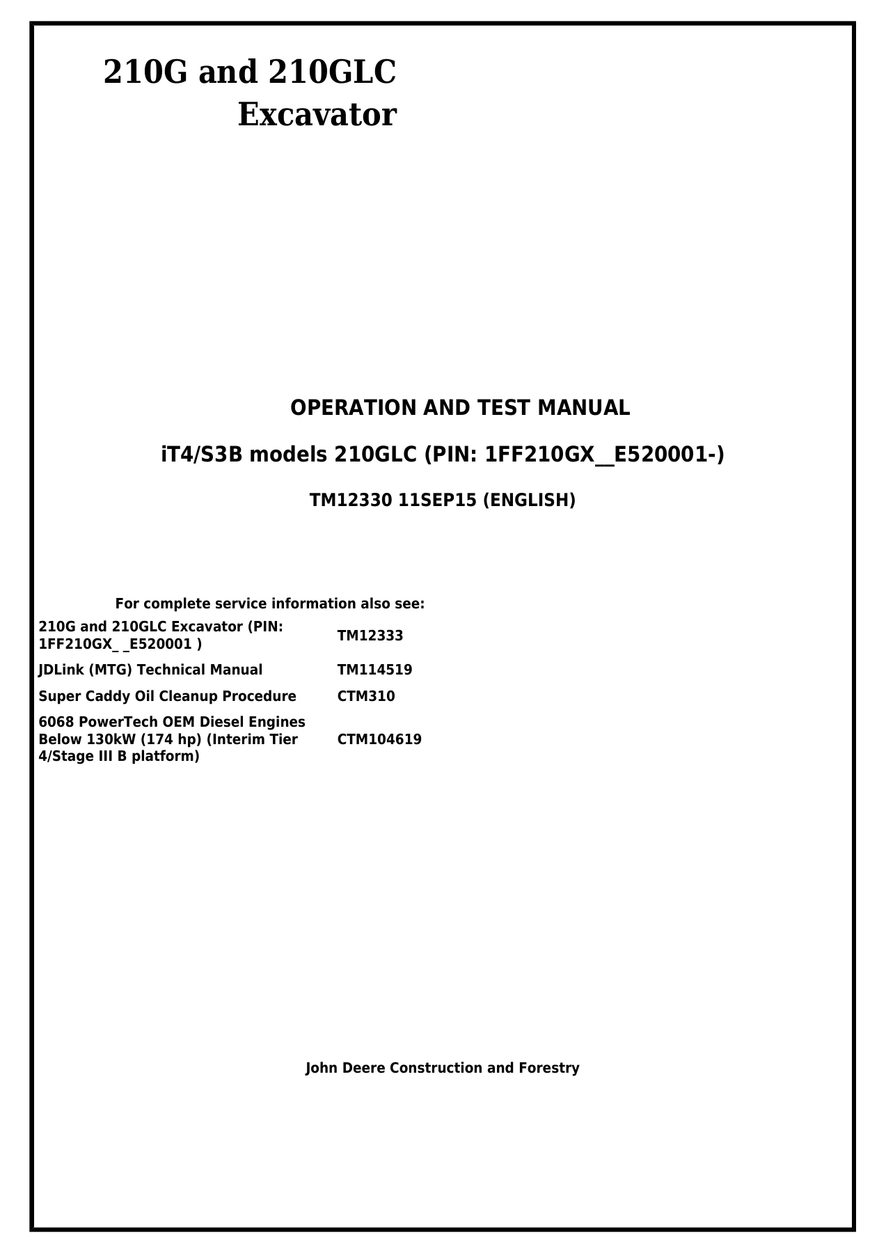
This is the complete John Deere 210G and 210GLC Excavator Operation and Test Manual bearing document number TM12330, published September 2015. It covers the iT4/S3B configured 210GLC with PIN 1FF210GX_E520001- and the corresponding 210G model. The manual is written for the experienced technician and combines operational checkout procedures with in-depth diagnostic and test information, making it the reference document for servicing these excavators in the field or workshop.
File Details
- Manual Type: Operation and Test Manual
- Brand: John Deere
- Models Covered: 210G and 210GLC Excavator
- Engine: 6068HT086 (Interim Tier 4, 6068 PowerTech OEM Diesel below 130 kW / 174 hp)
- Document Number: TM12330
- Edition / Date: 11SEP15 (September 2015)
- Language: English
- File Format: PDF
Chapters Covered
The manual is organized into sections and groups, each opening with the essential tools, service equipment, specifications, wear tolerances, and torque values needed for the job.
- Section 9000 – General Information: Group 01 Safety – safety alert symbols, protective clothing, high-pressure fluid hazards, battery safety, exhaust filter ash handling, fire prevention, and safe service practices.
- Section 9001 – Diagnostics: Group 10 Main Controller (MCZ) Diagnostic Trouble Codes; Group 20 Engine Control Unit (ECU) Diagnostic Trouble Codes; Group 30 Monitor Controller (DSZ) Diagnostic Trouble Codes; Group 40 Air Conditioner Controller (ACF) Diagnostic Trouble Codes.
- Section 9005 – Operational Checkout Procedure: Group 10 – complete walk-around and operator-seat operational checks for the 210G and 210GLC.
- Section 9010 – Engine: Group 05 Theory of Operation (engine identification, fuel system, cooling system, cold weather starting aid, engine speed control); Group 15 Diagnostic Information; Group 20 Adjustments; Group 25 Tests (including radiator temperature differential check).
- Section 9015 – Electrical System: Group 05 System Information; Group 10 System Diagrams (functional schematics, harness wiring diagrams for cab, machine, monitor, engine, engine interface, pump, and numerous sub-harnesses); Group 15 Sub-System Diagnostics (CAN theory, starting and charging, monitor controller, ECU, exhaust aftertreatment, main controller, wiper/washer, lighting, travel alarm, pilot shutoff, attachment control); Group 16 Monitor Operation and Service Menu; Group 20 References (Service ADVISOR™ and MPDr procedures, fuse and relay tests, sensor and solenoid tests, component removal and installation).
- Section 9020 – Power Train: Group 05 Theory of Operation (track adjuster and recoil spring, travel gear case); Group 15 Diagnostic Information (track chain conditions, idler and roller leakage, track shoe faults, undercarriage wear, swing bearing measurement).
- Section 9025 – Hydraulic System: Group 05 Theory of Operation (fan drive, pilot system, pilot shutoff, pilot control valves, pump regulators, engine speed sensing, control valve, check valves, main relief, circuit relief, regenerative circuits, flow rate control valves, swing motor, travel motor, cylinders, return filter, auxiliary system and kits); Group 15 Diagnostic Information (over 30 hydraulic fault procedures); Group 25 Tests (pilot pressure, spool actuating pressure, solenoid valve tests, relief valve tests, pump regulator, pump flow, motor leakage, cylinder drift, fan drive flow and fan speed).
- Section 9031 – Heating and Air Conditioning: Group 05 Theory of Operation; Group 15 Diagnostic Information (system will not operate, no air flow, insufficient cooling, constant cold, window fogging, heater faults); Group 25 Tests (visual inspection, compressor clutch, leak test, hose inspection, belt check, R134a system test, operating pressure diagnostic chart).
- Section 9900 – Dealer Fabricated Tools: Group 99 – DFT1218 Split Flange Hose Cap fabrication details.
Complete Bookmarks
The complete bookmarks in the “John Deere 210G 210GLC Excavator Operation and Test Manual TM12330 PDF Download” are as follows:
+Section 9000 – GENERAL INFORMATIONp. 7
+Group 01 – Safetyp. 7
+Section 9001 – DIAGNOSTICSp. 30
+Group 10 – Main Controller (MCZ) Diagnostic Trouble Codesp. 30
+Controller Area Network (CAN 0) Diagnosticsp. 31
+Controller Area Network (CAN 1) Diagnostic Procedurep. 43
+Interface Controller Area Network (N-CAN) Diagnosticsp. 56
+Engine Controller Area Network (Engine CAN) Diagnosticsp. 63
+Abnormal EEPROM Diagnostic Procedurep. 67
+Abnormal RAM Diagnostic Procedurep. 67
+Abnormal A/D Converter Diagnostic Procedurep. 68
+Abnormal Sensor Voltage Diagnostic Procedurep. 68
+Abnormal Engine Speed Diagnostic Procedurep. 71
+Engine Control Dial Sensor Circuit High Input Diagnostic Procedurep. 72
+Engine Control Dial Sensor Circuit Low Diagnostic Procedurep. 74
+Pump 1 Delivery Pressure Sensor Circuit High Input Diagnostic Procedurep. 76
+Pump 1 Delivery Pressure Sensor Circuit Low Input Diagnostic Procedurep. 78
+Pump 2 Delivery Pressure Sensor Circuit High Input Diagnostic Procedurep. 81
+Pump 2 Delivery Pressure Sensor Circuit Low Input Diagnostic Procedurep. 83
+Pump 1 Flow Control Pressure Sensor Circuit High Input Diagnostic Procedurep. 86
+Pump 1 Flow Control Pressure Sensor Circuit Low Input Diagnostic Procedurep. 88
+Pump 2 Flow Control Pressure Sensor Circuit High Input Diagnostic Procedurep. 91
+Pump 2 Flow Control Pressure Sensor Circuit Low Input Diagnostic Procedurep. 93
+Swing Pilot Pressure Sensor Circuit High Input Diagnostic Procedurep. 96
+Swing Pilot Pressure Sensor Circuit Low Input Diagnostic Procedurep. 98
+Boom Up Pilot Pressure Sensor Circuit High Input Diagnostic Procedurep. 101
+Boom Up Pilot Pressure Sensor Circuit Low Input Diagnostic Procedurep. 103
+Arm In Pilot Pressure Sensor Circuit High Input Diagnostic Procedurep. 106
+Arm In Pilot Pressure Sensor Circuit Low Input Diagnostic Procedurep. 108
+Travel Pilot Pressure Sensor Circuit High Input Diagnostic Procedurep. 111
+Travel Pilot Pressure Sensor Circuit Low Input Diagnostic Procedurep. 113
+Front Attachment Pilot Pressure Sensor Circuit High Input Diagnostic Procedurep. 116
+Front Attachment Pilot Pressure Sensor Circuit Low Input Diagnostic Procedurep. 118
+Pump 2 Flow Rate Limit Solenoid Valve Abnormal Feedback Diagnostic Procedurep. 121
+Pump 2 Flow Rate Limit Solenoid Valve Feedback High Current Diagnostic Procedurep. 124
+Pump 2 Flow Rate Limit Solenoid Valve Feedback Low Current Diagnostic Procedurep. 127
+Torque Control Solenoid Valve Abnormal Feedback Diagnostic Procedurep. 130
+Torque Control Solenoid Valve Feedback High Current Diagnostic Procedurep. 133
+Torque Control Solenoid Valve Feedback Low Current Diagnostic Procedurep. 136
+3-Spool Solenoid Valve Unit (SF) Abnormal Feedback Diagnostic Procedurep. 139
+3-Spool Solenoid Valve Unit (SF) Feedback High Input Diagnostic Procedurep. 142
+3-Spool Solenoid Valve Unit (SF) Feedback Low Input Diagnostic Procedurep. 145
+3-Spool Solenoid Valve Unit (SC) Abnormal Feedback Diagnostic Procedurep. 148
+3-Spool Solenoid Valve Unit (SC) Feedback High Input Diagnostic Procedurep. 151
+3-Spool Solenoid Valve Unit (SC) Feedback Low Input Diagnostic Procedurep. 154
+3-Spool Solenoid Valve Unit (SG) Abnormal Feedback Diagnostic Procedurep. 157
+3-Spool Solenoid Valve Unit (SG) Feedback High Input Diagnostic Procedurep. 160
+3-Spool Solenoid Valve Unit (SG) Feedback Low Input Diagnostic Procedurep. 163
+2-Speed Activation Solenoid Disconnected or Not Present Diagnostic Procedurep. 166
+Selector Valve Solenoid Valve Disconnected or Not Present Diagnostic Procedurep. 169
+Idle Stop Relay Circuit Malfunction Diagnostic Procedurep. 171
+Hydraulic Oil Temperature Sensor Circuit High Input Diagnostic Procedurep. 173
+Hydraulic Oil Temperature Sensor Circuit Low Input Diagnostic Procedurep. 175
+Abnormal Exhaust Filter Diagnostic Procedurep. 176
+Group 20 – Engine Control Unit (ECU) Diagnostic Trouble Codesp. 178
+Coolant Level Low—Moderately Severe Level Diagnostic Procedurep. 179
+Coolant Level Low—Most Severe Level Diagnostic Procedurep. 181
+Battery Voltage Low Diagnostic Procedurep. 182
+Variable Speed Fan Solenoid Open Circuit Diagnostic Procedurep. 183
+Variable Speed Fan Solenoid Short Circuit Diagnostic Procedurep. 185
+Reversing Fan Switch Active Too Long Diagnostic Procedurep. 186
+Glow Plug Relay Low Current Diagnostic Procedurep. 188
+Glow Plug Relay High Current Diagnostic Procedurep. 190
+Glow Plug Relay Output Low When Relay Active Diagnostic Procedurep. 192
+Glow Plug Relay Output High When Relay Not Active Diagnostic Procedurep. 193
+Requested Speed/Speed Limit Diagnostic Procedurep. 195
+Hydraulic Temperature Diagnostic Procedurep. 196
+Fan Speed High—Moderately Severe Level Diagnostic Procedurep. 197
+Fan Speed Low—Most Severe Level Diagnostic Procedurep. 199
+Reversing Fan Solenoid Open Circuit Diagnostic Procedurep. 201
+Reversing Fan Solenoid Short Circuit Diagnostic Procedurep. 203
+Group 30 – Monitor Controller (DSZ) Diagnostic Trouble Codesp. 204
+Monitor Internal Temperature Sensor Diagnostic Procedurep. 204
+Alternator Alarm Diagnostic Procedurep. 205
+Fuel Level Sensor Open Circuit Diagnostic Procedurep. 206
+Fuel Level Sensor Shorted Circuit Diagnostic Procedurep. 208
+Flash Memory Read/Write Error Diagnostic Procedurep. 209
+External RAM Read/Write Error Diagnostic Procedurep. 210
+Abnormal EEPROM Diagnostics Procedurep. 210
+Communication Terminal:Communication Error Diagnostic Procedurep. 211
+Abnormal Internal RAM Diagnostic Procedurep. 212
+Hydraulic Oil Filter Restriction Alarm Diagnostic Procedurep. 214
+Pilot Control Shut-Off Lever Alarm Diagnostic Procedurep. 216
+Group 40 – Air Conditioner Controller (ACF) Diagnostic Trouble Codesp. 219
+Open Circuit in Air Recirculation Sensor Diagnostic Procedurep. 220
+Short-Circuited Air Recirculation Sensor Diagnostic Procedurep. 222
+Open Circuit in Ambient Air Temperature Sensor Diagnostics Procedurep. 224
+Short-Circuited Ambient Air Temperature Sensor Diagnostic Procedurep. 226
+Short-Circuited Solar Radiation Sensor Diagnostic Procedurep. 228
+Open Circuit In Air Conditioner Freeze Control Switch Diagnostic Procedurep. 230
+Short-Circuited Air Conditioner Freeze Control Switch Diagnostic Procedurep. 232
+Abnormal Air Conditioner and Heater Blower Port Change Servomotor Diagnostic Procedurep. 234
+Abnormal Air Conditioner and Heater Mixer Servomotor Diagnostic Procedurep. 236
+Abnormal Air Conditioner High/Low Pressure Switch Diagnostic Procedurep. 238
+Communication Error Diagnostic Procedurep. 240
+CAN Bus Off Error Diagnostic Procedurep. 241
+Section 9005 – OPERATIONAL CHECKOUT PROCEDUREp. 243
+Group 10 – Operational Checkout Procedurep. 243
+Operational Checks—Key Switch On, Engine On Checksp. 243
+Section 9010 – ENGINEp. 306
+Group 05 – Theory of Operationp. 306
+Group 15 – Diagnostic Informationp. 315
+Group 20 – Adjustmentsp. 316
+Group 25 – Testsp. 317
+Section 9015 – ELECTRICAL SYSTEMp. 324
+Group 05 – System Informationp. 324
+Group 10 – System Diagramsp. 334
+Group 15 – Sub-System Diagnosticsp. 493
+Group 16 – Monitor Operationp. 584
+Group 20 – Referencesp. 596
+Component Checksp. 618
+Section 9020 – POWER TRAINp. 669
+Group 05 – Theory of Operationp. 669
+Group 15 – Diagnostic Informationp. 672
+Noisy or Loose Track Chain Diagnostic Procedurep. 672
+Tight Track Chain Diagnostic Procedurep. 672
+Frequent Track Chain Sag Adjustment Required Diagnostic Procedurep. 673
+Excessive Oil Leakage From Front Idler, Track Rollers, or Carrier Rollers Diagnostic Procedurep. 673
+Bent Track Shoes Diagnostic Procedurep. 674
+‘Popping” of Track Diagnostic Procedurep. 675
+Cracked Track Link Diagnostic Procedurep. 676
+Chipped Link Rails Diagnostic Procedurep. 677
+Individual Undercarriage Component Wear Diagnostic Procedurep. 677
+Section 9025 – HYDRAULIC SYSTEMp. 686
+Group 05 – Theory of Operationp. 686
+Group 15 – Diagnostic Informationp. 874
+All Hydraulic Functions Slow Diagnostic Procedurep. 874
+Hydraulic Oil Overheats Diagnostic Procedurep. 878
+No Hydraulic Functions Diagnostic Procedurep. 881
+Poor Combined Operation Diagnostic Procedurep. 883
+All Functions Cannot Be Operated Diagnostic Procedurep. 884
+Function Does Not Stop When Control Lever Released Diagnostic Procedurep. 885
+Some Functions Cannot Be Operated, All Others Are Normal Diagnostic Procedurep. 886
+All Functions Slow Diagnostic Procedurep. 888
+Functions Move in Opposite Directionp. 889
+All Dig Functions Slow or No Powerp. 890
+Some Dig Functions Slow (Not All)p. 891
+Load Drifts Down When Control Lever is in Neutral Position Diagnostic Procedurep. 893
+Load Falls When Control Valve is Actuated To Raise Load With Engine Running at Slow Idle Diagnostic Procedurep. 894
+H/P (High Power) Function Does Not Operate, PWR (Power) Mode is Normal Diagnostic Procedurep. 895
+Swing Speed Slow in Both Directions Diagnostic Procedurep. 897
+Swing Speed Slow or Does Not Operate in One Direction Diagnostic Procedurep. 899
+Upperstructure Drift with Swing Valve in Neutral Diagnostic Procedurep. 901
+Swing Function Does Not Operate Diagnostic Procedurep. 903
+Travel Park Brakes Do Not Apply Diagnostic Procedurep. 904
+Track Will Not Move in One Direction Diagnostic Procedurep. 905
+Track Will Not Move in Either Direction Diagnostic Procedurep. 907
+Machine Mistracks at All Speeds in Both Directions Diagnostic Procedurep. 909
+Slow Travel Speed or Low Power Diagnostic Procedurep. 911
+Combined Travel and Dig Functions Slow or No Power Diagnostic Procedurep. 913
+Travel is ‘Jerky” Diagnostic Procedurep. 914
+Machine Will Not Hold Back and Park Brakes Engage and Disengage When Traveling Down an Incline Diagnostic Procedurep. 915
+Machine Will Not Turn Smoothly in One Direction or Park Brake Grabs Diagnostic Procedurep. 915
+Group 25 – Testsp. 972
+Section 9031 – HEATING AND AIR CONDITIONINGp. 1058
+Group 05 – Theory of Operationp. 1058
+Group 15 – Diagnostic Informationp. 1060
+Air Conditioning System Does Not Operate Diagnostic Procedurep. 1060
+No Air Flow From Heater and Air Conditioner Vents Diagnostic Procedurep. 1062
+Air Conditioning Does Not Cool Interior of Cab Diagnostic Procedurep. 1066
+Air Conditioning Runs Constantly, Too Cold Diagnostic Procedurep. 1069
+Interior Windows Continue to Fog Using Air Conditioner Diagnostics Procedurep. 1071
+Heater System Does Not Operate Diagnostic Procedurep. 1073
+Heater Does Not Warm Interior of Cab Diagnostic Procedurep. 1077
+Interior Windows Continue to Fog Using Heater Diagnostic Procedurep. 1079
+Group 25 – Testsp. 1083
+Visual Inspection of Componentsp. 1084
+Section 9900 – DEALER FABRICATED TOOLSp. 1093
+Group 99 – Dealer Fabricated Toolsp. 1093
This Operation and Test Manual is not simply a repair guide — it is the diagnostic companion to the repair sections. It equips the technician to identify the majority of routine failures quickly through structured diagnostic procedures, DTC-driven troubleshooting, and precise test and adjustment sequences. Every group begins with the relevant specifications, wear tolerances, and torque values so the reader has the critical data at hand before starting work. The electrical section alone contains dozens of harness wiring diagrams and sub-system diagnostics, while the hydraulic section provides full theory, fault isolation, and test procedures for pumps, motors, valves, and cylinders.
Diagnostics and Troubleshooting Coverage
The diagnostic content is extensive and is one of the manual’s strongest features. The Main Controller (MCZ) Diagnostic Trouble Codes section walks through CAN communication errors, sensor circuit faults (high/low input), solenoid valve feedback faults, and exhaust filter-related codes. The Engine Control Unit (ECU) Diagnostic Trouble Codes section covers coolant level, battery voltage, variable speed fan, glow plug relay, reversing fan, and fan speed faults. The Monitor Controller (DSZ) and Air Conditioner Controller (ACF) diagnostic sections round out the electronic troubleshooting with codes for communication errors, sensor circuits, servomotors, and pressure switches. Each DTC entry includes a step-by-step diagnostic procedure with connector checks, voltage and resistance measurements, and a clear YES/NO result path that leads to repair or replacement. The manual also includes detailed CAN bus diagnostics for CAN 0, CAN 1, interface CAN, and engine CAN networks, including termination resistor checks and resistance specifications.
Hydraulic and Electrical Test Procedures
For the hydraulic system, the manual provides practical test procedures that can be performed in the field: pilot pressure regulating valve test and adjustment, control valve spool actuating pilot pressure test, dig regenerative and arm regenerative solenoid valve tests, power dig solenoid valve test, torque control solenoid valve test, main relief and power dig valve test and adjustment, circuit relief valve test, swing motor and travel motor crossover relief valve tests, pump regulator minimum and maximum flow tests, pump flow test, motor leakage tests, cylinder drift test, and fan drive pump flow and fan speed tests. The electrical system includes fuse and relay tests, pressure sensor resistance and voltage tests, solenoid and proportional solenoid tests, temperature sensor tests, alternator test, battery and relay checks, and detailed connector repair procedures for DEUTSCH™, WEATHER PACK™, Metri-Pack™, and CINCH™ connectors.
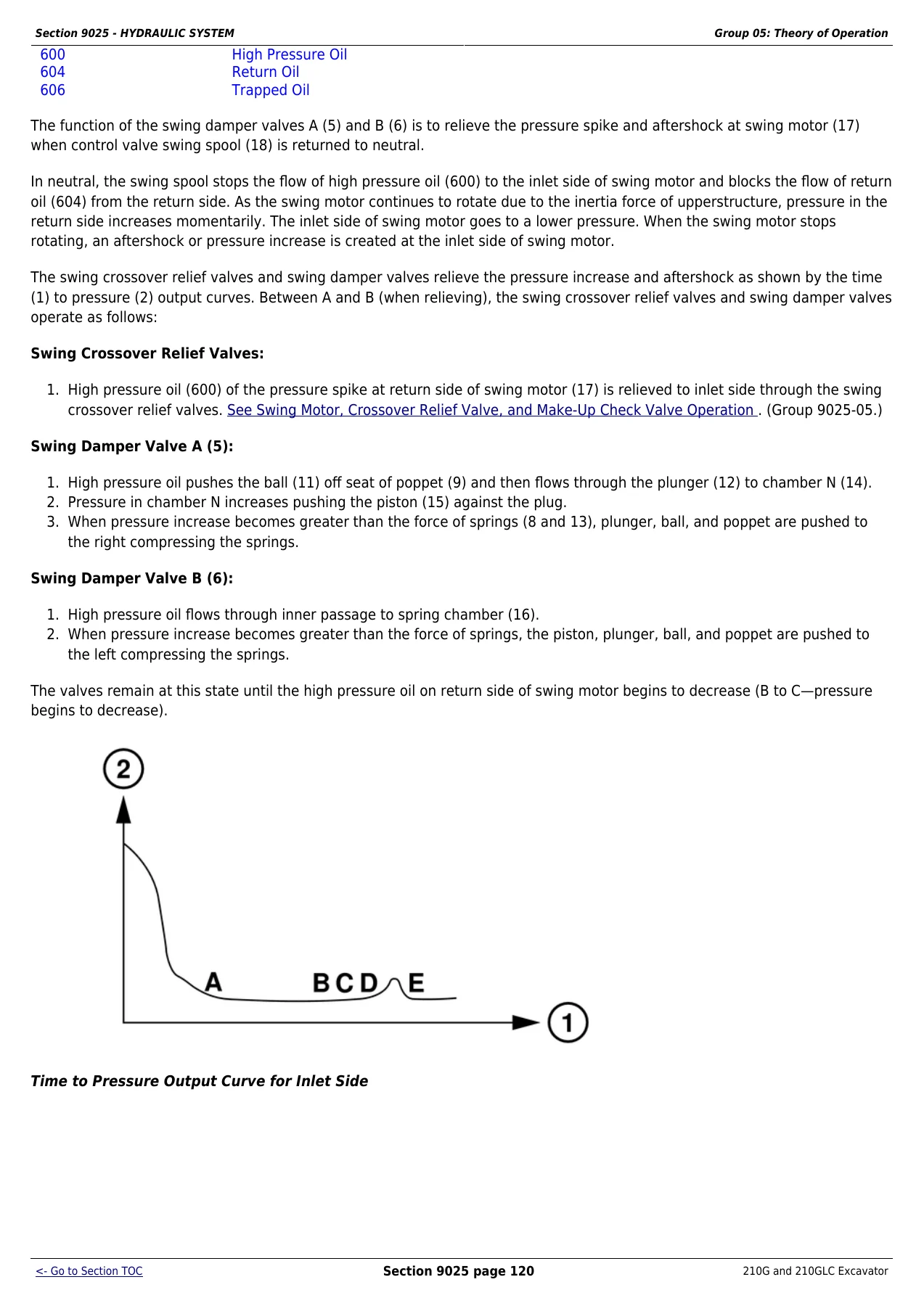
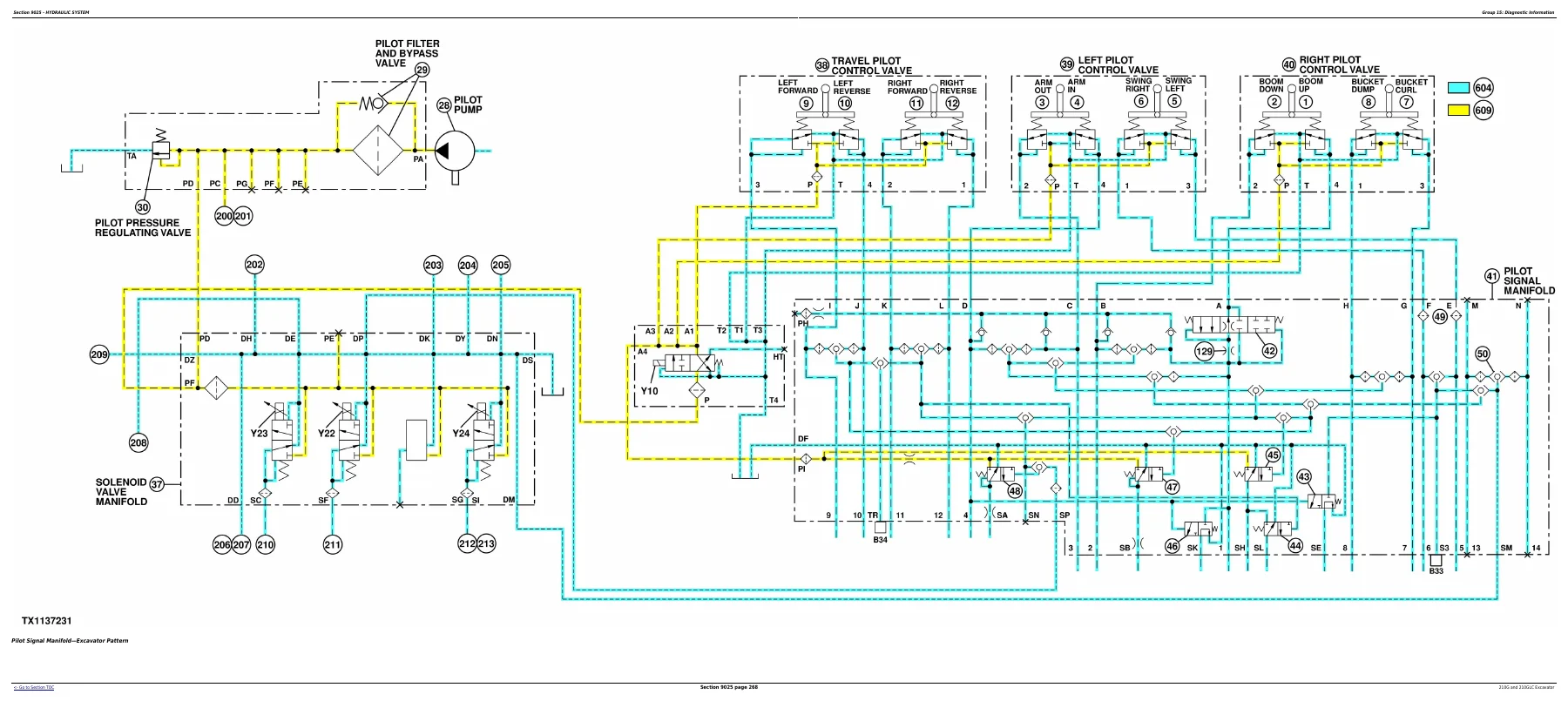
IMAGES PREVIEW
Who This Manual Is For
This John Deere 210G and 210GLC Operation and Test Manual TM12330 is intended for experienced technicians, service managers, and equipment owners who need to diagnose, test, and verify the performance of these excavators. It is the document used to perform operational checkout, interpret diagnostic trouble codes, run hydraulic and electrical tests, and confirm that repairs have restored the machine to specification. It is also valuable for anyone who needs to understand the theory behind the systems before troubleshooting — the theory of operation sections explain how each circuit and component is meant to function, which makes fault isolation far more efficient.
Why This Manual Matters
Having the correct test procedures and specifications on hand prevents guesswork. The wrong adjustment or an incorrect test method can damage components, shorten service life, or leave a fault unresolved. This manual gives you the exact pressures, flow rates, resistances, voltages, cycle times, and torque values that John Deere specifies for the 210G and 210GLC, along with the step-by-step procedures to measure and adjust them. The operational checkout procedure alone provides a structured way to verify every major machine function, from the horn and gauges to travel tracking and cycle times, ensuring nothing is overlooked before the machine goes back to work.
Instant PDF Delivery
This listing is for a PDF download of the John Deere 210G and 210GLC Excavator Operation and Test Manual TM12330. After payment, you can download the file immediately — no shipping, no waiting. The PDF can be viewed on any computer, tablet, or smartphone and can be printed for use in the workshop. Whether you are diagnosing a fault code, testing a hydraulic function, or performing an operational checkout, this manual puts the complete John Deere test and diagnostic information for the 210G and 210GLC right at your fingertips.
What Our Customers Say
🌟 Related Products
Discover more professional manuals for your equipment

Hitachi Hydraulic Excavators Data Book - 2nd Edition (2009) - PDF Download

Kubota SVL95-2s Compact Track Loader Workshop Manual PDF Download

Kalmar DRG 420-450 Reachstackers Maintenance Manual – PDF Download


Reviews
There are no reviews yet.