John Deere 2154D Log Loader Diagnostic Operation and Test Manual TM10323
$39.95 Original price was: $39.95.$24.95Current price is: $24.95.
Complete diagnostic operation and test manual for John Deere 2154D Log Loader covering MCX, ECU, ICX, ACX diagnostic trouble codes, hydraulic and electrical system testing, engine diagnostics, and full operational checkout procedures.
Description
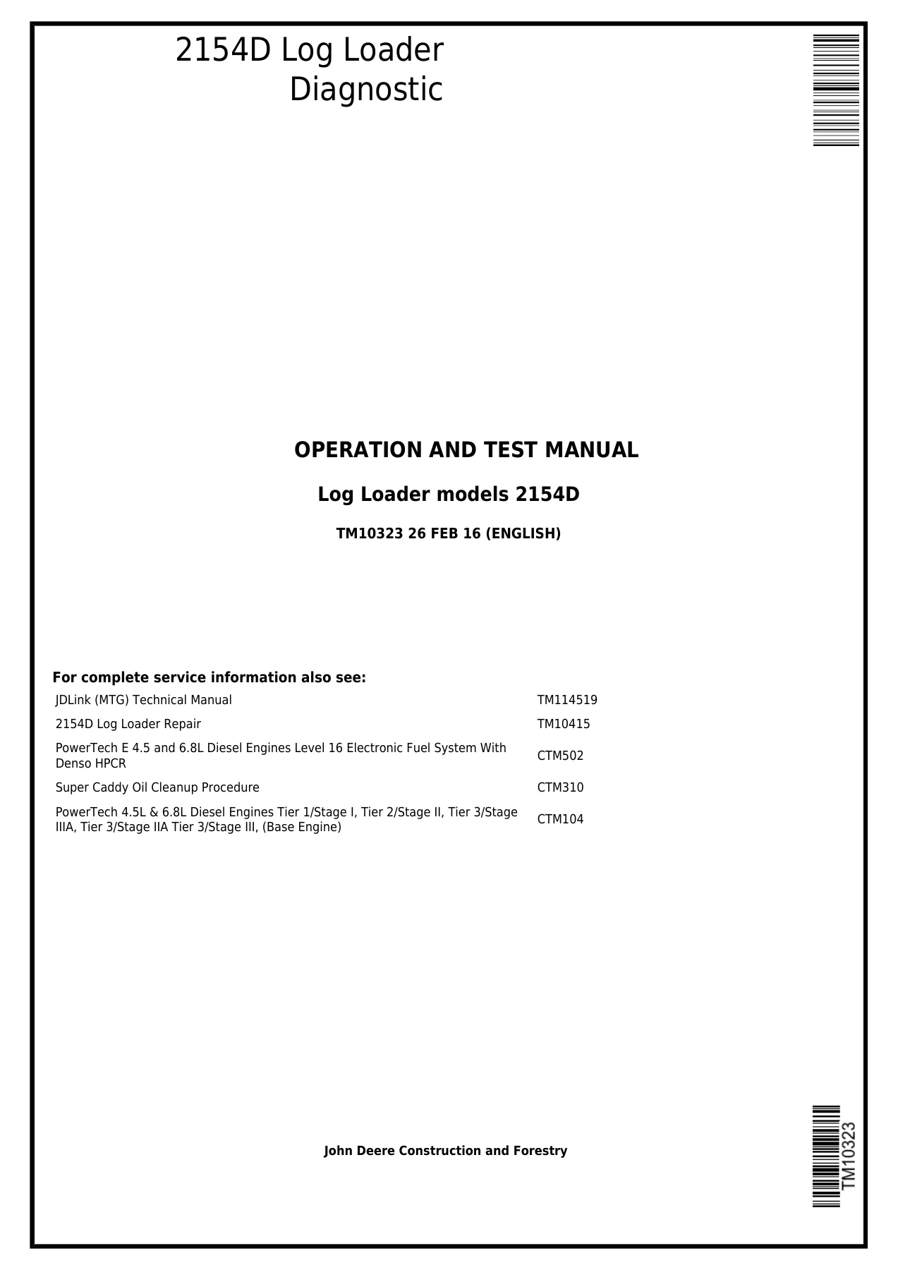
John Deere 2154D Log Loader Diagnostic Operation and Test Manual TM10323
This comprehensive diagnostic operation and test manual is the essential companion for technicians servicing the John Deere 2154D Log Loader. Published under document number TM10323 with a revision date of 26 February 2016, this manual provides the complete framework for diagnosing, testing, and verifying every major system on the machine. Whether you are chasing an intermittent fault, performing a structured operational checkout, or needing the exact diagnostic trouble code flow for the Main Controller (MCX), Engine Control Unit (ECU), Information Controller (ICX), or Air Conditioner Controller (ACX), this manual delivers the procedures, specifications, and test sequences required to get the job done correctly.
File Details
- Manual Type: Diagnostic Operation and Test Manual
- Brand: John Deere
- Model: 2154D Log Loader
- Document Number: TM10323
- Edition/Revision: 26 FEB 16 (English)
- Language: English
- File Format: PDF
- Page Count: Approximately 920+ pages
Chapters Covered
- Section 9000 – General Information
- Group 01 – Safety (Recognize Safety Information, Follow Safety Instructions, Operate Only If Qualified, Protective Equipment, Avoid Unauthorized Machine Modifications, Inspect Machine, Stay Clear of Moving Parts, Avoid High-Pressure Fluids, Avoid High-Pressure Oils, Beware of Exhaust Fumes, Prevent Fires, In Case of Machine Fire, Clean Debris From Machine, Prevent Battery Explosions, Handle Chemical Products Safely, Dispose of Waste Properly, Prepare for Emergencies, Control Pattern, Use Steps and Handholds Correctly, Start Only From Operator’s Seat, Use and Maintain Seat Belt, Prevent Unintended Machine Movement, Operate Machine Safely, Avoid Work Site Hazards, Keep Riders Off Machine, Use Care When Swinging Machine, Travel Safely, Operate Booms With Care, Avoid Power Lines, Avoid Backover Accidents, Avoid Machine Tip Over, Operating On Slopes, Add and Operate Attachments Safely, Inspect and Maintain Operator Protective Structures and Guards, Park and Prepare for Service Safely, Service Machines Safely, Service Cooling System Safely, Service Accumulator Systems Safely, Prevent Acid Burns, Remove Paint Before Welding or Heating, Make Welding Repairs Safely, Drive Metal Pins Safely)
- Section 9001 – Diagnostics
- Group 10 – Main Controller (MCX) Diagnostic Trouble Codes (EEPROM Malfunction, RAM Malfunction, A/D Conversion Malfunction, Harness Diagnostics, Engine Speed Dial Diagnostics, Pump 1 & 2 Delivery Pressure Sensor Diagnostics, Pump 1 & 2 Control Pressure Sensor Diagnostics, Swing Pressure Sensor Diagnostics, Boom Up Pilot Pressure Sensor Diagnostics, Arm In Pilot Pressure Sensor Diagnostics, Travel Pilot Pressure Sensor Diagnostics)
- Group 20 – Engine Control Unit (ECU) Diagnostic Trouble Codes (Throttle #3 Diagnostics, Throttle #2 Diagnostics, Throttle Diagnostics, Intake Air Temperature Sensor Diagnostics, Proportional Fan Speed Solenoid Diagnostics, Fan Manual Reverse Mode Input Diagnostics, Hydraulic Oil Temperature Sensor Diagnostics)
- Group 30 – Information Controller (ICX) Diagnostic Trouble Codes (Controller Hardware Diagnostics, Main Controller Communication Diagnostics, Monitor Controller Communication Diagnostics)
- Group 40 – Air Conditioner Controller (ACX) Diagnostic Trouble Codes (Harness Diagnostics for Mix Door, Mode Encoder, In-Cab Ambient Temperature Sensor, Outdoor Ambient Temperature Sensor, Coolant Temperature Sensor, Solar Radiation Sensor)
- Section 9005 – Operational Checkout
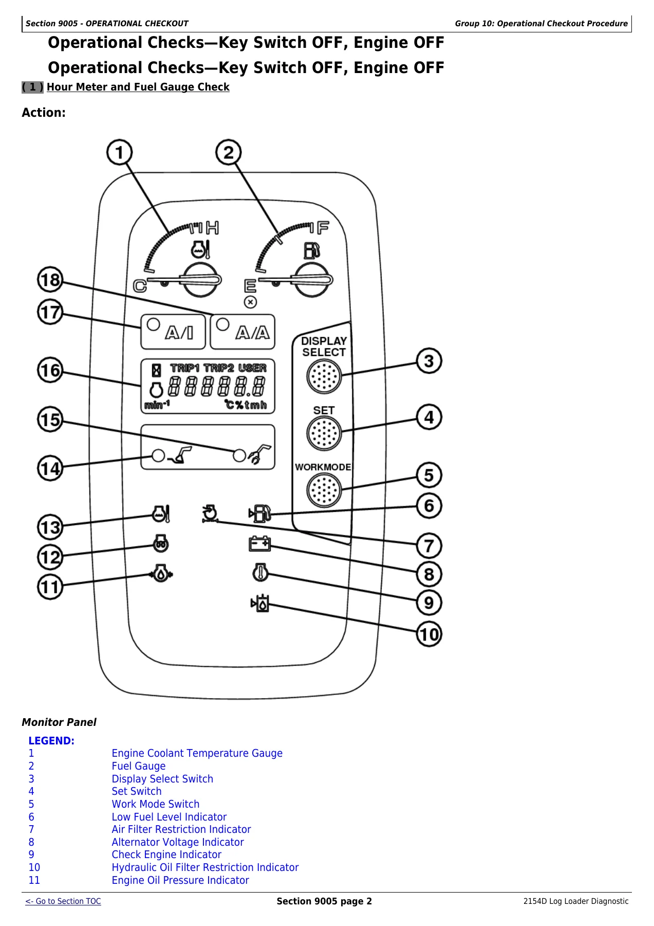
- Group 10 – Operational Checkout Procedure (Diagnostic Trouble Codes Check, Hour Meter and Fuel Gauge Check, Gauge, Monitor, and Battery Disconnect Relay Checks, Monitor and Gauge Circuit Checks, Pilot Control Shutoff Valve Check, Engine Speed Dial Check, E Mode Check, P Mode Check, HP Mode Check, Auto-Idle Circuit Check, Auto-Acceleration Circuit Check, Travel Alarm Check, Travel Alarm Cancel Switch Circuit Check, Disable Travel Function – Ground Saw Switch Option, Hydraulic Oil Tank Pressurization Check, Hydraulic Oil Tank Pressure Relief Switch Check, Swing Park Brake and Circuit Drift Check, Swing Power Check, Pedal Swing Check, Boom, Arm, and Attachment Drift Check, Control Valve Lift Check Test, Arm Regenerative Valve Operation Check, Grapple Tilt Regenerative Valve Operation Check, Travel Speed Selection Check, Travel System Tracking Check, Travel System Tracking Checks While Operating a Hydraulic Function, Travel System Maneuverability Check, Cycle Times Check, Heater and Air Conditioner Controls Check)
- Section 9010 – Engine
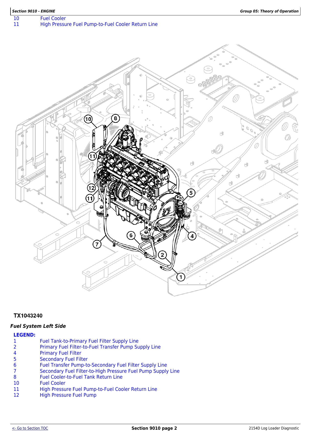
- Group 05 – Theory of Operation (Engine Fuel System Component Location, Additional Water Separator Operation, Diesel Fuel Fired Coolant Heater Operation, Engine Cooling System Component Location, Cold Weather Starting Aid Operation, Engine Speed Control System Operation)
- Group 15 – Diagnostic Information (Auto-Idle Does Not Work, Engine Coolant Temperature Above Normal, Engine Coolant Temperature Below Normal)
- Group 25 – Tests (Radiator Temperature Differential Test)
- Section 9015 – Electrical System
- Group 05 – System Information (Electrical Diagram Information, Explanation of Wire Markings, System Functional Schematic Diagram, Wiring Diagram, Component Location Diagram, Connector End View Diagram)
- Group 10 – System Diagrams (System Functional Schematics, Relay and Fuse Block Component Location, Fuse Component Location, Harness Wiring Diagrams)
- Group 15 – Sub-System Diagnostics (Controller Area Network Theory of Operation, Starting and Charging Circuit Theory of Operation, Monitor Controller Circuit Theory of Operation, Engine Control Unit Circuit Theory of Operation, Main Controller Circuit Theory of Operation, Information Controller Circuit Theory of Operation, Travel Alarm Circuit Theory of Operation, Windshield Wiper and Washer Circuit Theory of Operation, Ground Saw Theory of Operation, Auxiliary Oil Cooler Circuit Theory of Operation, JDLink Circuit Theory of Operation)
- Group 16 – Monitor Operation (Monitor Service Mode Operation, Diagnostic Display Unit Operation)
- Group 20 – References (Reading Diagnostic Trouble Codes With Monitor Display, Reading Diagnostic Trouble Codes With Diagnostic Display Unit, Service ADVISOR Diagnostic Application, Service ADVISOR Connection Procedure, Reading Engine Diagnostic Trouble Codes With Service ADVISOR, Service ADVISOR Interactive Tests, JDLink Connection Procedure, Fuse Test, Relay Test, Pressure Sensor Test, Solenoid Test, Proportional Solenoid Test, Temperature Sensor Test, Engine Speed Sensor Test, Alternator Test, Electrical Component Checks, Battery Remove and Install, Rear Cover Remove and Install, Main Controller Remove and Install, Engine Control Unit Remove and Install, Information Controller Remove and Install, Monitor Controller Remove and Install, Key Switch Remove and Install, Switch Panel Remove and Install, Travel Alarm Remove and Install, Left Console Remove and Install, Right Console Remove and Install, Disconnect Tab Retainer Connectors, Disconnecting Spring Wire Clip Connectors, Replace DEUTSCH Connectors, Install DEUTSCH Contacts, Replace WEATHER PACK Connector, Install WEATHER PACK Contacts, Replace Metri-Pack Connectors, Replace CINCH Connectors, Install CINCH Contact, Repair 32 and 48 Way CINCH Connectors, Remove Connector Body from Blade Terminals)
- Section 9020 – Power Train
- Group 05 – Theory of Operation (Track Adjuster and Recoil Spring Operation, Travel Gearbox Operation)
- Group 15 – Diagnostic Information (Diagnose Undercarriage Components Malfunctions, Individual Undercarriage Component Wear, Measure Swing Bearing Wear)
Complete PDF Bookmark TreeComplete Bookmarks
The complete bookmarks in the “John Deere 2154D Log Loader Diagnostic Operation and Test Manual TM10323” are as follows:
Table of contentsp. 2FOREWORDp. 4TECHNICAL INFORMATION FEEDBACK FORMp. 5+Section 9000 – GENERAL INFORMATIONp. 7
+Group 01 – Safetyp. 7
Recognize Safety Informationp. 7Follow Safety Instructionsp. 7Operate Only If Qualifiedp. 7Wear Protective Equipmentp. 9Avoid Unauthorized Machine Modificationsp. 9Inspect Machinep. 9Stay Clear of Moving Partsp. 10Avoid High-Pressure Fluidsp. 10Avoid High-Pressure Oilsp. 11Beware of Exhaust Fumesp. 11Prevent Firesp. 12In Case of Machine Firep. 13Clean Debris From Machinep. 13Prevent Battery Explosionsp. 13Handle Chemical Products Safelyp. 14Dispose of Waste Properlyp. 14Prepare for Emergenciesp. 15Control Patternp. 15Use Steps and Handholds Correctlyp. 15Start Only From Operator′s Seatp. 15Use and Maintain Seat Beltp. 16Prevent Unintended Machine Movementp. 16Operate Machine Safelyp. 16Avoid Work Site Hazardsp. 17Keep Riders Off Machinep. 18Use Care When Swinging Machinep. 18Travel Safelyp. 18Operate Booms With Carep. 19Avoid Power Linesp. 19Avoid Backover Accidentsp. 20Avoid Machine Tip Overp. 20Operating On Slopesp. 21Add and Operate Attachments Safelyp. 21Inspect and Maintain Operator Protective Structures and Guardsp. 22Park and Prepare for Service Safelyp. 22Service Machines Safelyp. 23Service Cooling System Safelyp. 23Service Accumulator Systems Safelyp. 23Prevent Acid Burnsp. 25Remove Paint Before Welding or Heatingp. 25Make Welding Repairs Safelyp. 26Drive Metal Pins Safelyp. 26+Section 9001 – DIAGNOSTICSp. 30
+Group 10 – Main Controller (MCX) Diagnostic Trouble Codesp. 30
Main Controller (MCX) Diagnostic Trouble Codesp. 30+EEPROM Malfunction Diagnosticsp. 30
Code Checkp. 30Machine Function Checkp. 30Code Checkp. 30Machine Function Checkp. 30+RAM Malfunction Diagnosticsp. 30
Code Checkp. 30Machine Function Checkp. 30Code Checkp. 31Machine Function Checkp. 31+A/D Conversion Malfunction Diagnosticsp. 31
Code Checkp. 31Machine Function Checkp. 31Code Checkp. 31Machine Function Checkp. 31+Harness diagnosticsp. 31
Sensor Checkp. 31Continuity Checkp. 31Sensor Checkp. 32Continuity Checkp. 32+Engine Speed Dial Diagnosticsp. 33
Engine Speed Dial Resistance Checkp. 33Engine Speed Dial Voltage Checkp. 33Sensor Circuit Voltage Checkp. 33Open Circuit Checkp. 33Short Circuit Checkp. 34Harness Voltage Checkp. 34Engine Speed Dial Resistance Checkp. 34Engine Speed Dial Voltage Checkp. 34Sensor Circuit Voltage Checkp. 34Open Circuit Checkp. 34Short Circuit Checkp. 34Harness Voltage Checkp. 34+Pump 1 Delivery Pressure Sensor Diagnosticsp. 35
Sensor Checkp. 35Sensor Circuit Checkp. 35Open Circuit Checkp. 35Short Circuit Checkp. 35Harness Voltage Checkp. 36Sensor Checkp. 36Sensor Circuit Checkp. 36Open Circuit Checkp. 36Short Circuit Checkp. 36Harness Voltage Checkp. 36+Pump 2 Delivery Pressure Sensor Diagnosticsp. 37
Sensor Checkp. 37Sensor Circuit Checkp. 37Open Circuit Checkp. 37Short Circuit Checkp. 37Harness Voltage Checkp. 38Sensor Checkp. 38Sensor Circuit Checkp. 38Open Circuit Checkp. 38Short Circuit Checkp. 38Harness Voltage Checkp. 38+Pump 1 Control Pressure Sensor Diagnosticsp. 39
Sensor Checkp. 39Sensor Circuit Checkp. 39Open Circuit Checkp. 39Short Circuit Checkp. 39Harness Voltage Checkp. 40Sensor Checkp. 40Sensor Circuit Checkp. 40Open Circuit Checkp. 40Short Circuit Checkp. 40Harness Voltage Checkp. 40+Pump 2 Control Pressure Sensor Diagnosticsp. 41
Sensor Checkp. 41Sensor Circuit Checkp. 41Open Circuit Checkp. 41Short Circuit Checkp. 41Harness Voltage Checkp. 42Sensor Checkp. 42Sensor Circuit Checkp. 42Open Circuit Checkp. 42Short Circuit Checkp. 42Harness Voltage Checkp. 42+Swing Pressure Sensor Diagnosticsp. 43
Sensor Checkp. 43Sensor Circuit Checkp. 43Open Circuit Checkp. 43Short Circuit Checkp. 43Harness Voltage Checkp. 44Sensor Checkp. 44Sensor Circuit Checkp. 44Open Circuit Checkp. 44Short Circuit Checkp. 44Harness Voltage Checkp. 44+Boom Up Pilot Pressure Sensor Diagnosticsp. 45
Sensor Checkp. 45Sensor Circuit Checkp. 45Open Circuit Checkp. 45Short Circuit Checkp. 45Harness Voltage Checkp. 46Sensor Checkp. 46Sensor Circuit Checkp. 46Open Circuit Checkp. 46Short Circuit Checkp. 46Harness Voltage Checkp. 46+Arm In Pilot Pressure Sensor Diagnosticsp. 47
Sensor Checkp. 47Sensor Circuit Checkp. 47Open Circuit Checkp. 47Short Circuit Checkp. 47Harness Voltage Checkp. 48Sensor Checkp. 48Sensor Circuit Checkp. 48Open Circuit Checkp. 48Short Circuit Checkp. 48Harness Voltage Checkp. 48+Travel Pilot Pressure Sensor Diagnosticsp. 49
Sensor Checkp. 49Sensor Circuit Checkp. 49Open Circuit Checkp. 49Short Circuit Checkp. 49Harness Voltage Checkp. 50Sensor Checkp. 50Sensor Circuit Checkp. 50Open Circuit Checkp. 50Short Circuit Checkp. 50Harness Voltage Checkp. 50+Group 20 – Engine Control Unit (ECU) Diagnostic Trouble Codesp. 51
Engine Control Unit (ECU) Diagnostic Trouble Codesp. 51+Throttle #3 Diagnosticsp. 52
Connector Checkp. 52Harness Voltage Checkp. 52Harness Checkp. 52Main Controller (MCX) Voltage Checkp. 52Connector Checkp. 53Harness Voltage Checkp. 53Harness Checkp. 53Main Controller (MCX) Voltage Checkp. 53+Throttle #3 Diagnosticsp. 54
Connector Checkp. 54Harness Voltage Checkp. 54Harness Checkp. 54Main Controller (MCX) Voltage Checkp. 54Connector Checkp. 55Harness Voltage Checkp. 55Harness Checkp. 55Main Controller (MCX) Voltage Checkp. 55+Throttle #2 Diagnosticsp. 56
Connector Checkp. 56Harness Voltage Checkp. 56Component Checkp. 56Harness Checkp. 56Main Controller (MCX) Voltage Checkp. 57Connector Checkp. 57Harness Voltage Checkp. 57Component Checkp. 57Harness Checkp. 57Main Controller (MCX) Voltage Checkp. 57+Throttle #2 Diagnosticsp. 58
Connector Checkp. 58Harness Voltage Checkp. 58Harness Checkp. 58Main Controller (MCX) Voltage Checkp. 58Connector Checkp. 59Harness Voltage Checkp. 59Harness Checkp. 59Main Controller (MCX) Voltage Checkp. 59+Throttle Diagnosticsp. 60
Connector Checkp. 60Harness Voltage Checkp. 60Harness Checkp. 60Main Controller (MCX) Voltage Checkp. 60Connector Checkp. 61Harness Voltage Checkp. 61Harness Checkp. 61Main Controller (MCX) Voltage Checkp. 61+Throttle Diagnosticsp. 62
Connector Checkp. 62Harness Voltage Checkp. 62Harness Checkp. 62Main Controller (MCX) Voltage Checkp. 62Connector Checkp. 63Harness Voltage Checkp. 63Harness Checkp. 63Main Controller (MCX) Voltage Checkp. 63+Intake Air Temperature Sensor Diagnosticsp. 63
Connector Checkp. 63Temperature Sensor Checkp. 63Open Circuit Checkp. 63Connector Checkp. 63Temperature Sensor Checkp. 63Open Circuit Checkp. 63+Intake Air Temperature Sensor Diagnosticsp. 63
Connector Checkp. 64Temperature Sensor Checkp. 64Short Circuit Checkp. 64Connector Checkp. 64Temperature Sensor Checkp. 64Short Circuit Checkp. 64+Proportional Fan Speed Solenoid Diagnosticsp. 64
Connector Checkp. 64Solenoid Checkp. 64Harness Checkp. 65Connector Checkp. 65Solenoid Checkp. 65Harness Checkp. 65+Fan Manual Reverse Mode Input Diagnosticsp. 66
Connector Checkp. 66Power Checkp. 66Harness Checkp. 66Reversing Fan Switch Continuity Checkp. 66Reversing Fan Switch Function Checkp. 67Connector Checkp. 67Power Checkp. 67Harness Checkp. 67Reversing Fan Switch Continuity Checkp. 67Reversing Fan Switch Function Checkp. 67+Hydraulic Oil Temperature Sensor Diagnosticsp. 68
Connector Checkp. 68Sensor Checkp. 68Open Circuit Checkp. 68Short Circuit Checkp. 68Connector Checkp. 68Sensor Checkp. 68Open Circuit Checkp. 68Short Circuit Checkp. 68+Hydraulic Oil Temperature Sensor Diagnosticsp. 69
Connector Checkp. 69Sensor Checkp. 69Open Circuit Checkp. 69Short Circuit Checkp. 69Connector Checkp. 69Sensor Checkp. 69Open Circuit Checkp. 69Short Circuit Checkp. 69+Group 30 – Information Controller (ICX) Diagnostic Trouble Codesp. 70
Information Controller (ICX) Diagnostic Trouble Codesp. 70+Controller Hardware Diagnosticsp. 70
Code Checkp. 70Machine Function Checkp. 70Code Checkp. 70Machine Function Checkp. 70+Controller Hardware Diagnosticsp. 70
Code Checkp. 70Machine Function Checkp. 71Code Checkp. 71Machine Function Checkp. 71+Controller Hardware Diagnosticsp. 71
Code Checkp. 71Machine Function Checkp. 71Code Checkp. 71Machine Function Checkp. 71+Controller Hardware Diagnosticsp. 71
Code Checkp. 71Machine Function Checkp. 72Code Checkp. 72Machine Function Checkp. 72+Controller Hardware Diagnosticsp. 72
Code Checkp. 72Machine Function Checkp. 72Code Checkp. 72Machine Function Checkp. 72+Main Controller Communication Diagnosticsp. 72
Connector Checkp. 72Harness Checkp. 72Connector Checkp. 73Harness Checkp. 73+Monitor Controller Communication Diagnosticsp. 73
Connector Checkp. 73Harness Checkp. 73Connector Checkp. 73Harness Checkp. 7309 – Main Controller Communication Timeoutp. 7310 – Satellite Terminal Communication Timeoutp. 73+Group 40 – Air Conditioner Controller (ACX) Diagnostic Trouble Codesp. 74
Air Conditioner Controller (ACX) Diagnostic Trouble Codesp. 74+Harness Diagnosticsp. 74
Connector Checkp. 74Open Circuit Checkp. 74Connector Checkp. 74Open Circuit Checkp. 74+Harness Diagnosticsp. 74
Connector Checkp. 74Short Circuit Checkp. 75Connector Checkp. 75Short Circuit Checkp. 75+Harness Diagnosticsp. 76
Connector Checkp. 76Open Circuit Checkp. 76Continuity Checkp. 76Connector Checkp. 76Open Circuit Checkp. 76Continuity Checkp. 76+Harness Diagnosticsp. 76
Connector Checkp. 76Open Circuit Checkp. 77Connector Checkp. 77Open Circuit Checkp. 77+Harness Diagnosticsp. 77
Connector Checkp. 77Short Circuit Checkp. 77Connector Checkp. 77Short Circuit Checkp. 77+Harness Diagnosticsp. 77
Connector Checkp. 77Open Circuit Checkp. 78Connector Checkp. 78Open Circuit Checkp. 78+Harness Diagnosticsp. 78
Connector Checkp. 78Short Circuit Checkp. 78Connector Checkp. 78Short Circuit Checkp. 78+Harness Diagnosticsp. 78
Connector Checkp. 79Open Circuit Checkp. 79Connector Checkp. 79Open Circuit Checkp. 79+Harness Diagnosticsp. 79
Connector Checkp. 79Short Circuit Checkp. 79Connector Checkp. 79Short Circuit Checkp. 79+Harness Diagnosticsp. 79
Connector Checkp. 80Open Circuit Checkp. 80Connector Checkp. 80Open Circuit Checkp. 80+Harness Diagnosticsp. 80
Connector Checkp. 80Short Circuit Checkp. 80Connector Checkp. 81Short Circuit Checkp. 81+Section 9005 – OPERATIONAL CHECKOUTp. 83
+Group 10 – Operational Checkout Procedurep. 83
Operational Checkoutp. 83+Diagnostic Trouble Codes Checkp. 83
Display and Clear Diagnostic Trouble Codesp. 83Display and Clear Diagnostic Trouble Codesp. 83+Operational Checks—Key Switch OFF, Engine OFFp. 84
Hour Meter and Fuel Gauge Checkp. 84Hour Meter and Fuel Gauge Checkp. 85+Operational Checks—Key Switch ON, Engine OFFp. 86
Gauges, Monitor, and Battery Disconnect Relay Checksp. 86Horn Circuit Checkp. 87Travel Lever and Pedal Neutral Checksp. 88Swing Pedal Neutral Checkp. 89Light Circuit Checksp. 89Rear Cab Work Light Circuit Checkp. 90Windshield Wiper Controls Check—Rear Entry Cabp. 91Windshield Wiper Controls Check—Side Entry Cabp. 92Windshield Washer Circuit Checkp. 93Gauges, Monitor, and Battery Disconnect Relay Checksp. 94Horn Circuit Checkp. 94Travel Lever and Pedal Neutral Checksp. 94Swing Pedal Neutral Checkp. 94Light Circuit Checksp. 94Rear Cab Work Light Circuit Checkp. 94Windshield Wiper Controls Check—Rear Entry Cabp. 94Windshield Wiper Controls Check—Side Entry Cabp. 94Windshield Washer Circuit Checkp. 94+Operational Checks—Key Switch ON, Engine ONp. 95
Monitor and Gauge Circuit Checksp. 95Pilot Control Shutoff Valve Checkp. 96Engine Speed Dial Checkp. 97E (Economy) Mode Checkp. 98P (Standard) Mode Checkp. 100HP (high power) Mode Check (S.N. —210693)p. 101HP (high power) Mode Check (S.N. 210694— )p. 102Auto-Idle Circuit Checkp. 104Auto-Acceleration Circuit Checkp. 105Travel Alarm Checkp. 107Travel Alarm Cancel Switch Circuit Checkp. 108Disable Travel Function – Ground Saw Switch Optionp. 108Hydraulic Oil Tank Pressurization Checkp. 109Hydraulic Oil Tank Pressure Relief Switch Checkp. 110Swing Park Brake and Circuit Drift Checkp. 110Swing Power Checkp. 112Pedal Swing Checkp. 113Boom, Arm, and Attachment Drift Checkp. 114Control Valve Lift Check Testp. 116Arm Regenerative Valve Operation Checkp. 118Grapple Tilt (Live Heel Grapple) Regenerative Valve Operation Checkp. 119Travel Speed Selection Checkp. 120Travel System Tracking Checkp. 122Travel System Tracking Checks While Operating a Hydraulic Functionp. 123Travel System Maneuverability Checkp. 124Cycle Times Check—2154D (S.N. —210693)p. 125Cycle Times Check—2154D (S.N. 210694— )p. 128Heater and Air Conditioner Controls Check—Rear Entry Cabp. 130Heater and Air Conditioner Controls Check—Side Entry Cabp. 131Monitor and Gauge Circuit Checksp. 133Pilot Control Shutoff Valve Checkp. 133Engine Speed Dial Checkp. 133E (Economy) Mode Checkp. 133P (Standard) Mode Checkp. 133HP (high power) Mode Check (S.N. —210693)p. 133HP (high power) Mode Check (S.N. 210694— )p. 133Auto-Idle Circuit Checkp. 133Auto-Acceleration Circuit Checkp. 133Travel Alarm Checkp. 133Travel Alarm Cancel Switch Circuit Checkp. 133Disable Travel Function – Ground Saw Switch Optionp. 133Hydraulic Oil Tank Pressurization Checkp. 133Hydraulic Oil Tank Pressure Relief Switch Checkp. 133Swing Park Brake and Circuit Drift Checkp. 133Swing Power Checkp. 133Pedal Swing Checkp. 133Boom, Arm, and Attachment Drift Checkp. 133Control Valve Lift Check Testp. 133Arm Regenerative Valve Operation Checkp. 133Grapple Tilt (Live Heel Grapple) Regenerative Valve Operation Checkp. 133Travel Speed Selection Checkp. 133Travel System Tracking Checkp. 133Travel System Tracking Checks While Operating a Hydraulic Functionp. 133Travel System Maneuverability Checkp. 133Cycle Times Check—2154D (S.N. —210693)p. 133Cycle Times Check—2154D (S.N. 210694— )p. 133Heater and Air Conditioner Controls Check—Rear Entry Cabp. 133Heater and Air Conditioner Controls Check—Side Entry Cabp. 133+Section 9010 – ENGINEp. 135
+Group 05 – Theory of Operationp. 135
Engine Fuel System Component Locationp. 135Additional Water Separator Operation (if equipped)p. 137Diesel Fuel Fired Coolant Heater Operation (if equipped)p. 139Engine Cooling System Component Locationp. 141Cold Weather Starting Aid Operationp. 144Engine Speed Control System Operation (S.N. —210693)p. 145Engine Speed Control System Operation (S.N. 210694— )p. 148+Group 15 – Diagnostic Informationp. 151
PowerTech E PowerTech E is a trademark of Deere & Company 4.5 L and 6.8 L (4045 and 6068) John Deere Enginesp. 151+Auto-Idle Does Not Workp. 152
Air Filter Checkp. 152Cooling Package Covers and Baffles Checkp. 152Cooling Package Screen Checkp. 152Fan Shroud Checkp. 152Fan Blade Checkp. 153Fan Drive Speed Checkp. 153Coolant Temperature Checkp. 153Fan Blade Checkp. 153Fan Drive Speed Checkp. 153Fuse Checkp. 154Relay Checkp. 154Battery Voltage Checkp. 154Fuse Checkp. 154Relay Checkp. 154Check Engine Speedp. 155Travel Pressure Sensor Checkp. 155Attachment Pressure Sensor Checkp. 155Auto-Idle Switch Checkp. 155Air Filter Checkp. 155Cooling Package Covers and Baffles Checkp. 155Cooling Package Screen Checkp. 155Fan Shroud Checkp. 155Fan Blade Checkp. 155Fan Drive Speed Checkp. 155Coolant Temperature Checkp. 155Fan Blade Checkp. 155Fan Drive Speed Checkp. 155Fuse Checkp. 155Relay Checkp. 155Battery Voltage Checkp. 155Fuse Checkp. 155Relay Checkp. 155Check Engine Speedp. 155Travel Pressure Sensor Checkp. 155Attachment Pressure Sensor Checkp. 155Auto-Idle Switch Checkp. 155+Group 25 – Testsp. 156
Radiator Temperature Differential Testp. 156+Section 9015 – ELECTRICAL SYSTEMp. 163
+Group 05 – System Informationp. 163
Electrical Diagram Informationp. 163Electrical Schematic Symbolsp. 169+Group 10 – System Diagramsp. 172
Explanation of Wire Markingsp. 172Fuse and Relay Specificationsp. 173System Functional Schematic, Component Location, and Wire Diagram Master Legendp. 179System Splice Master Legendp. 190System Functional Schematicp. 192Cab Harness (W1) Component Locationp. 221Cab Harness (W1) Wiring Diagramp. 226Machine Harness (W2) Component Locationp. 233Machine Harness (W2) Wiring Diagramp. 235Monitor Harness (W3) Component Locationp. 240Monitor Harness (W3) Wiring Diagramp. 243Cab-to-Machine Extension Harness (W4) Component Locationp. 245Cab-to-Machine Extension Harness (W4) Wiring Diagramp. 250Engine Harness (W5) Component Locationp. 252Engine Harness (W5) Wiring Diagramp. 255Engine Interface Harness (W6) Component Locationp. 257Engine Interface Harness (W6) Wiring Diagramp. 259Frame Harness (W7) Component Locationp. 261Frame Harness (W7) Wiring Diagramp. 263Pump Harness (W8) Component Locationp. 265Pump Harness (W8) Wiring Diagramp. 267Load Center Harness—Valve-In-Head (W9) Component Locationp. 269Load Center Harness—Valve-In-Head (W9) Wiring Diagramp. 273Load Center Harness—Non-Valve-In-Head (W9) Component Locationp. 276Load Center Harness—Non-Valve-In-Head (W9) Wiring Diagramp. 280Load Center Harness—Ground Saw (W9) Component Locationp. 283Load Center Harness—Ground Saw (W9) Wiring Diagramp. 287Upper Cab Harness—Side Entry Cab (W10) Component Locationp. 290Upper Cab Harness—Side Entry Cab (W10) Wiring Diagramp. 292Upper Cab Harness—Rear Entry Cab (W10) Component Locationp. 294Upper Cab Harness—Rear Entry Cab (W10) Wiring Diagramp. 296Frame Harness—to—Load Center Extension Harness (W11) Component Locationp. 297Frame Harness—to—Load Center Extension Harness (W11) Wiring Diagramp. 298Cab Tilt Harness (W12) Component Locationp. 300Cab Tilt Harness (W12) Wiring Diagramp. 302Cab Tilt Switch Harness (W13) Component Locationp. 303Cab Tilt Switch Harness (W13) Wiring Diagramp. 304Cab Tilt Relay Power Harness (W14) Component Locationp. 304Cab Tilt Relay Power Harness (W14) Wiring Diagramp. 306Cab Tilt Fuse Harness (W15) Component Locationp. 306Cab Tilt Fuse Harness (W15) Wiring Diagramp. 308Front Cab Work Light Harness (W16) Component Locationp. 309Front Cab Work Light Harness (W16) Wiring Diagramp. 312Rear Cab Work Light Harness (W17) Component Locationp. 313Rear Cab Work Light Harness (W17) Wiring Diagramp. 314Front Attachment Work Light Boom Harness (W18) Component Locationp. 316Front Attachment Work Light Boom Harness (W18) Wiring Diagramp. 318Work Light Arm Harness—Log Loader (W19) Component Locationp. 318Work Light Arm Harness—Log Loader (W19) Wiring Diagramp. 320Reversing Fan Switch (W21) Component Locationp. 321Reversing Fan Switch (W21) Wiring Diagramp. 322Information Controller (ICX) Sub Harness (W22) Component Locationp. 322Information Controller (ICX) Sub Harness (W22) Wiring Diagramp. 324Power Converter Harness (W23) Component Locationp. 325Power Converter Harness (W23) Wiring Diagramp. 327Travel Alarm Harness (W24) Component Locationp. 328Travel Alarm Harness (W24) Wiring Diagramp. 329Cab Dome Light Harness (W25) Component Locationp. 329Cab Dome Light Harness (W25) Wiring Diagramp. 331Fuel Fired Coolant Heater Timer Harness (W26) Component Locationp. 333Fuel Fired Coolant Heater Timer Harness (W26) Wiring Diagramp. 335Fuel Fired Coolant Heater Harness (W27) Component Locationp. 335Fuel Fired Coolant Heater Harness (W27) Wiring Diagramp. 336Fuel Fired Coolant Heater Extension Harness (W28) Component Locationp. 337Fuel Fired Coolant Heater Extension Harness (W28) Wiring Diagramp. 338Auxiliary Oil Cooler Harness (W29) Component Locationp. 339Auxiliary Oil Cooler Harness (W29) Wiring Diagramp. 344Powered Condenser Harness (W30) Component Locationp. 346Powered Condenser Harness (W30) Wiring Diagramp. 348Oil Transfer Pump Harness (W31) Component Locationp. 350Oil Transfer Pump Harness (W31) Wiring Diagramp. 352Heater and Air Conditioner Harness—Rear Entry Cab (W32) Component Locationp. 354Heater and Air Conditioner Harness—Rear Entry Cab (W32) Wiring Diagramp. 356Heater and Air Conditioner Temperature Control Harness—Rear Entry Cab (W33) Component Locationp. 357Heater and Air Conditioner Temperature Control Harness—Rear Entry Cab (W33) Wiring Diagramp. 358Right Console Harness (W34) Component Locationp. 359Right Console Harness (W34) Wiring Diagramp. 363Right Console Harness—Ground Saw (W34) Component Locationp. 365Right Console Harness—Ground Saw (W34) Wiring Diagramp. 367Left Console Harness (W35) Component Locationp. 368Left Console Harness (W35) Wiring Diagramp. 369Left Console Harness—Ground Saw (W35) Component Locationp. 370Left Console Harness—Ground Saw (W35) Wiring Diagramp. 371Right Hand Control Lever Harness—Valve-In-Head (W36) Component Locationp. 372Right Hand Control Lever Harness—Valve-In-Head (W36) Wiring Diagramp. 373Left Hand Control Lever Harness—Valve-In-Head (W37) Component Locationp. 374Left Hand Control Lever Harness—Valve-In-Head (W37) Wiring Diagramp. 375Right Hand Control Lever Harness—Non-Valve-In-Head (W38) Component Locationp. 376Right Hand Control Lever Harness—Non-Valve-In-Head (W38) Wiring Diagramp. 377Left Hand Control Lever Harness—Non-Valve-In-Head (W39) Component Locationp. 378Left Hand Control Lever Harness—Non-Valve-In-Head (W39) Wiring Diagramp. 379Valve-In-Head Cab Harness (W41) Component Locationp. 380Valve-In-Head Cab Harness (W41) Wiring Diagramp. 381Valve-In-Head Boom Harness (W42) Component Locationp. 382Valve-In-Head Boom Harness (W42) Wiring Diagramp. 384Valve-In-Head Arm Harness (W43) Component Locationp. 384Valve-In-Head Arm Harness (W43) Wiring Diagramp. 386Solenoid Harness (W46) Component Locationp. 386Solenoid Harness (W46) Wiring Diagramp. 388Diode Harness (W47) Component Locationp. 389Diode Harness (W47) Wiring Diagramp. 390Alternator Harness (W48) Component Locationp. 391Alternator Harness (W48) Wiring Diagramp. 392Air Conditioner Compressor Clutch Harness (W49) Component Locationp. 393Air Conditioner Compressor Clutch Harness (W49) Wiring Diagramp. 394Heater and Air Conditioner Harness—Side Entry Cab (W51) Component Locationp. 396Heater and Air Conditioner Harness—Side Entry Cab (W51) Wiring Diagramp. 398Ground Saw Pilot Harness (W57) Component Locationp. 400Ground Saw Pilot Harness (W57) Wiring Diagramp. 402Ground Saw Pilot Extension Harness (W58) Component Locationp. 403Ground Saw Pilot Extension Harness (W58) Wiring Diagramp. 404Fuel Filter Harness (W59) Component Locationp. 405Fuel Filter Harness (W59) Wiring Diagramp. 407JDLink™ Modular Telematics Gateway (MTG) Harness (W6002) Component Location—If Equippedp. 409JDLink™ Modular Telematics Gateway (MTG) Harness (W6002) Wiring Diagram—If Equippedp. 411+Group 15 – Sub-System Diagnosticsp. 413
Controller Area Network (CAN) Theory of Operationp. 413Starting and Charging Circuit Theory of Operationp. 415Monitor Controller Circuit Theory of Operationp. 418Engine Control Unit (ECU) Circuit Theory of Operationp. 425Main Controller (MCX) Circuit Theory of Operationp. 431Information Controller (ICX) Circuit Theory of Operationp. 438Travel Alarm Circuit Theory of Operationp. 440Windshield Wiper and Washer Circuit Theory of Operationp. 442Ground Saw Theory of Operationp. 445Auxiliary Oil Cooler Circuit Theory of Operationp. 447JDLink™ Circuit Theory of Operation—If Equippedp. 449+Group 16 – Monitor Operationp. 451
Monitor Service Mode Operationp. 451Diagnostic Display Unit (DDU) Operationp. 452+Group 20 – Referencesp. 453
Reading Diagnostic Trouble Codes With Monitor Displayp. 453Reading Diagnostic Trouble Codes With Diagnostic Display Unit (DDU)p. 454Service ADVISOR™ Diagnostic Applicationp. 454Service ADVISOR™ Connection Procedure To 9-Pin Diagnostic Connectorp. 454Reading Engine Diagnostic Trouble Codes With Service ADVISOR™ Diagnostic Applicationp. 456Service ADVISOR™ Interactive Testsp. 459JDLink™ Connection Procedure—If Equippedp. 459Fuse Testp. 460Relay Testp. 462Pressure Sensor Testp. 463Solenoid Testp. 464Proportional Solenoid Testp. 464Temperature Sensor Testp. 465Engine Speed (N) Sensor Testp. 465Alternator Testp. 467+Component Checksp. 469
Key Switch Checkp. 469Battery Relay Checkp. 469Battery Voltage Checkp. 470Fusible Link Checkp. 470Diode Checkp. 471Travel Alarm Checkp. 471CAN Bus Terminator Checkp. 472Key Switch Checkp. 473Battery Relay Checkp. 473Battery Voltage Checkp. 473Fusible Link Checkp. 473Diode Checkp. 473Travel Alarm Checkp. 473CAN Bus Terminator Checkp. 473Battery Remove and Installp. 474Rear Cover Remove and Install—Side Entry Cabp. 476Rear Cover Remove and Install—Rear Entry Cabp. 477Main Controller (MCX) Remove and Install—Side Entry Cabp. 478Main Controller (MCX) Remove and Install—Rear Entry Cabp. 479Engine Control Unit (ECU) Remove and Installp. 479Information Controller (ICX) Remove and Install—Side Entry Cabp. 480Information Controller (ICX) Remove and Install—Rear Entry Cabp. 480Monitor Controller Remove and Install—Side Entry Cabp. 481Monitor Controller Remove and Install—Rear Entry Cabp. 482Key Switch Remove and Install—Side Entry Cabp. 484Key Switch Remove and Install—Rear Entry Cabp. 485Switch Panel Remove and Install—Side Entry Cabp. 485Switch Panel Remove and Install—Rear Entry Cabp. 487Travel Alarm Remove and Install—Side Entry Cabp. 487Travel Alarm Remove and Install—Rear Entry Cabp. 488Left Console Remove and Installp. 488Right Console Remove and Install—Side Entry Cabp. 490Right Console Remove and Install—Rear Entry Cabp. 491Disconnect Tab Retainer Connectorsp. 492Disconnecting Spring Wire Clip Connectorsp. 492Replace DEUTSCH DEUTSCH is a trademark of the Deutsch Co. Connectorsp. 494Replace DEUTSCH DEUTSCH is a trademark of Deutsch Co. Rectangular or Triangular Connectorsp. 496Install DEUTSCH™ Contactsp. 498Replace WEATHER PACK WEATHER PACK is a trademark of Packard Electric. Connectorp. 499Install WEATHER PACK WEATHER PACK is a trademark of Packard Electric. Contactsp. 501Replace (Pull Type) Metri-Pack™ Connectorsp. 502Replace (Push Type) Metri-Pack™ Connectorsp. 503Replace CINCH CINCH is a trademark of the Cinch Co. Connectorsp. 503Install CINCH CINCH is a trademark of the Cinch Co. Contactp. 506Repair 32 and 48 Way CINCH CINCH is a trademark of the Cinch Co. Connectorsp. 508Remove Connector Body from Blade Terminalsp. 511+Section 9020 – POWER TRAINp. 513
+Group 05 – Theory of Operationp. 513
Track Adjuster and Recoil Spring Operationp. 513Travel Gearbox Operationp. 514+Group 15 – Diagnostic Informationp. 516
+Individual Undercarriage Component Wearp. 516
Incorrect track tension adjustmentp. 516Loose track shoesp. 516Grease leaking from track adjuster seals, grease fitting, or relief valvep. 516Material packing in sprocketp. 516Track sag less than specificationp. 517Grease leaking from track adjuster seals, grease fitting, or relief valvep. 517Loose plug, worn or damaged O-ring, or metal faced sealp. 517Excessive grouser wearp. 517Loose track shoesp. 517Excessive high speed operation on rough and rocky terrainp. 518High travel loads in reversep. 518Material packing in sprocketp. 518Excessive high speed operation on rough and rocky terrainp. 518Track shoes too wide for ground conditionsp. 519Repeated high impacts with roller tread on flanges caused by a loose or twisted track, or using shoes that are too widep. 519Some wear is normalp. 519Incorrect track tension adjustmentp. 519Loose track shoesp. 519Grease leaking from track adjuster seals, grease fitting, or relief valvep. 519Material packing in sprocketp. 519Track sag less than specificationp. 519Grease leaking from track adjuster seals, grease fitting, or relief valvep. 519Loose plug, worn or damaged O-ring, or metal faced sealp. 519Excessive grouser wearp. 519Loose track shoesp. 519Excessive high speed operation on rough and rocky terrainp. 519High travel loads in reversep. 519Material packing in sprocketp. 519Excessive high speed operation on rough and rocky terrainp. 519Track shoes too wide for ground conditionsp. 519Repeated high impacts with roller tread on flanges caused by a loose or twisted track, or using shoes that are too widep. 519Some wear is normalp. 519Measure Swing Bearing Wearp. 520+Section 9025 – HYDRAULIC SYSTEMp. 525
+Group 05 – Theory of Operationp. 525
Hydraulic System Operationp. 525Fan Drive System Operationp. 526Pilot System Operationp. 528Pilot Pump, Pressure Regulating Valve and Filter Operationp. 530Pilot Control Shutoff Valve Operationp. 531Pilot Control Valve Operationp. 533Travel Pilot Control Valve Operationp. 535Auxiliary Pilot Valve Operationp. 537Auxiliary Tandem Pilot Pump Hydraulic Circuitp. 538Swing Pedal Pilot Control Valve Operationp. 540Ground Saw Operationp. 542Pilot Operation of Control Valve Operationp. 548Pilot Signal Manifold Operationp. 554Pump 1, Pump 2 and Drive Gearbox Operationp. 570Pump 1 and Pump 2 Regulator Operationp. 573Engine Speed Sensing Control Circuit Operationp. 579Control Valve Operationp. 581Control Valve Check Valves Identification and Operationp. 598Main Relief and Power Boost Valve Circuit Operationp. 603Circuit Relief and Anticavitation Valve Operationp. 608Travel Flow Combiner Valve Operationp. 609Boom Lower Meter-In Cut Valve Operationp. 615Boom Regenerative Valve Circuit Operationp. 619Arm Regenerative Valve Circuit Operationp. 622Front Attachment Regenerative Valve Circuit Operationp. 628Boom and Arm Reduced Leakage Valves Operationp. 632Arm 1 Flow Rate Control Valve Circuit Operationp. 634Arm 2 Flow Rate Control Valve Circuit Operationp. 638Front Attachment Flow Rate Control Valve Circuit Operationp. 642Boom Flow Rate Control Valve Circuit Operationp. 647Swing Reduction Gearbox Operationp. 652Swing Motor, Crossover Relief Valve, and Make-Up Check Valve Operationp. 653Swing Motor Dampener Valve Operationp. 656Swing Motor Park Brake Release Circuit Operationp. 664Center Joint Operationp. 664Travel Motor and Park Brake Valve Operationp. 665Travel Motor Speed Circuit Operationp. 672Cylinder Operationp. 675Return Filter Operationp. 677+Group 15 – Diagnostic Informationp. 678
+Poor Combined Operationp. 678
Low hydraulic oil levelp. 678Cold hydraulic oilp. 678Oil viscosity too heavyp. 678Slow engine speedp. 678Air leak in pump suction linep. 679Pump control pilot pressure signal lowp. 679Pilot circuit malfunctionp. 679Restricted hydraulic oil tank suction screenp. 679Pump 1 or pump 2 regulator malfunctionp. 679Worn pumpp. 680Main relief and power boost valve setting too low or malfunctioningp. 680Low hydraulic oil levelp. 680Restricted hydraulic oil coolerp. 680Oil viscosity too lightp. 680Fan drive malfunctionp. 681Machine lift capacity exceededp. 681Restricted hydraulic oil return filterp. 681Main relief and power boost valve setting too low or malfunctioningp. 681Oil cooler bypass valve stuck openp. 681Restriction valve stuck closedp. 682Pump stuck at maximum displacementp. 682Pilot shutoff lever in lock position (rearward)p. 682Pilot shutoff valve malfunctionp. 682No hydraulic oilp. 682Pump drive failurep. 683Restricted hydraulic oil tank suction screenp. 683Front attachment pressure sensor (B32) or travel pressure sensor (B34) malfunctionp. 683Pilot control valve malfunctionp. 683Check valve stuckp. 683Pump 1 or pump 2 flow rate pilot valve or shuttle valves stuckp. 684Low hydraulic oil levelp. 684Cold hydraulic oilp. 684Oil viscosity too heavyp. 684Slow engine speedp. 684Air leak in pump suction linep. 684Pump control pilot pressure signal lowp. 684Pilot circuit malfunctionp. 684Restricted hydraulic oil tank suction screenp. 684Pump 1 or pump 2 regulator malfunctionp. 684Worn pumpp. 684Main relief and power boost valve setting too low or malfunctioningp. 684Low hydraulic oil levelp. 684Restricted hydraulic oil coolerp. 684Oil viscosity too lightp. 684Fan drive malfunctionp. 684Machine lift capacity exceededp. 684Restricted hydraulic oil return filterp. 684Main relief and power boost valve setting too low or malfunctioningp. 684Oil cooler bypass valve stuck openp. 684Restriction valve stuck closedp. 684Pump stuck at maximum displacementp. 684Pilot shutoff lever in lock position (rearward)p. 684Pilot shutoff valve malfunctionp. 684No hydraulic oilp. 684Pump drive failurep. 684Restricted hydraulic oil tank suction screenp. 684Front attachment pressure sensor (B32) or travel pressure sensor (B34) malfunctionp. 684Pilot control valve malfunctionp. 684Check valve stuckp. 684Pump 1 or pump 2 flow rate pilot valve or shuttle valves stuckp. 684+Function Moves in Opposite Directionp. 685
Pilot shutoff lever in lock position (rearward)p. 685Pilot shutoff valve malfunctionp. 685Low pilot oil pressurep. 685Control valve spool stuckp. 685Pilot control valve malfunctionp. 686Pilot cap loosep. 686Pilot control valve or hydraulic line malfunctionp. 686Swing Park Brake Release Pilot Valve (port SH) spool stuckp. 686Control valve spool stuckp. 686Restricted pilot filterp. 687Torque control solenoid valve malfunctionp. 687Low pilot oil pressurep. 687Restricted pilot shutoff solenoid valvep. 687Pilot control valve malfunctionp. 688Pilot control valve linesp. 688Control valve spool stuckp. 688Circuit relief valvep. 688Cylinder damage and/or seals leakingp. 688Pilot control lines connected incorrectlyp. 689Pilot shutoff lever in lock position (rearward)p. 689Pilot shutoff valve malfunctionp. 689Low pilot oil pressurep. 689Control valve spool stuckp. 689Pilot control valve malfunctionp. 689Pilot cap loosep. 689Pilot control valve or hydraulic line malfunctionp. 689Swing Park Brake Release Pilot Valve (port SH) spool stuckp. 689Control valve spool stuckp. 689Restricted pilot filterp. 689Torque control solenoid valve malfunctionp. 689Low pilot oil pressurep. 689Restricted pilot shutoff solenoid valvep. 689Pilot control valve malfunctionp. 689Pilot control valve linesp. 689Control valve spool stuckp. 689Circuit relief valvep. 689Cylinder damage and/or seals leakingp. 689Pilot control lines connected incorrectlyp. 689+Function Moves in Opposite Directionp. 690
Hydraulic system malfunctionp. 690Pilot circuit malfunctionp. 690Pump 1 or pump 2 regulator malfunctionp. 690Pilot circuit malfunctionp. 690Control valve leakagep. 691Cylinder leakagep. 691Circuit relief valve setting too low or malfunctioningp. 691Control valve spool stuckp. 691Pump 1 or pump 2 flow rate pilot valve spool stuckp. 691Cylinder leakagep. 692Circuit relief valve setting too low or malfunctioningp. 692Boom and arm reduced leakage valves (switch valve and poppet) malfunctioningp. 692Boom manual lower screw loosep. 692Control valve leakagep. 693Check valve (lift check) leakagep. 693Slow engine speedp. 693Power mode switch malfunctionp. 693Pilot control lines connected incorrectlyp. 694Hydraulic system malfunctionp. 694Pilot circuit malfunctionp. 694Pump 1 or pump 2 regulator malfunctionp. 694Pilot circuit malfunctionp. 694Control valve leakagep. 694Cylinder leakagep. 694Circuit relief valve setting too low or malfunctioningp. 694Control valve spool stuckp. 694Pump 1 or pump 2 flow rate pilot valve spool stuckp. 694Cylinder leakagep. 694Circuit relief valve setting too low or malfunctioningp. 694Boom and arm reduced leakage valves (switch valve and poppet) malfunctioningp. 694Boom manual lower screw loosep. 694Control valve leakagep. 694Check valve (lift check) leakagep. 694Slow engine speedp. 694Power mode switch malfunctionp. 694Pilot control lines connected incorrectlyp. 694+Swing Function Does Not Operatep. 695
Slow engine speedp. 695Swing motor crossover relief valve malfunctionp. 695Control valve leakagep. 695Swing motor leakagep. 695Swing park brake not fully releasedp. 696Pump 2 wornp. 696Pilot circuit malfunctionp. 696Swing motor make-up check valve leakagep. 696Swing motor crossover relief valve malfunctionp. 696Control valve stickingp. 697Swing park brake not engagingp. 697Pilot circuit malfunctionp. 697Swing park brake malfunctionp. 697Control valve stuckp. 697Mechanical failure of swing motor or gearboxp. 698Slow engine speedp. 698Swing motor crossover relief valve malfunctionp. 698Control valve leakagep. 698Swing motor leakagep. 698Swing park brake not fully releasedp. 698Pump 2 wornp. 698Pilot circuit malfunctionp. 698Swing motor make-up check valve leakagep. 698Swing motor crossover relief valve malfunctionp. 698Control valve stickingp. 698Swing park brake not engagingp. 698Pilot circuit malfunctionp. 698Swing park brake malfunctionp. 698Control valve stuckp. 698Mechanical failure of swing motor or gearboxp. 698+Machine Will Not Turn Smoothly In One Direction Or Park Brake Grabsp. 699
Park brake piston stuck, spring broke, or orifice pluggedp. 699Mechanical failure of travel motor and gearboxp. 699Pilot circuit malfunctionp. 699Travel motor crossover relief valve malfunctionp. 699Control valve stuckp. 700Counterbalance valve spool stuckp. 700Center joint leakagep. 700Pilot circuit malfunctionp. 700Travel motor crossover relief valve malfunctionp. 700Control valve stuckp. 701Counterbalance valve spool stuckp. 701Mechanical failure of travel motor or gearboxp. 701Center joint leakagep. 701Incorrect track sag adjustmentp. 701Pilot control valve malfunctionp. 702Travel motor crossover relief valvep. 702Ground Saw Diverter Valvep. 702Servo piston shuttle valve leakagep. 702Travel motor leakagep. 702Center joint leakagep. 703Pump 1 or pump 2 regulator malfunctionp. 703Travel flow combiner valve circuit malfunctionp. 703Incorrect track sag adjustmentp. 703Travel motor crossover relief valve malfunctionp. 704Travel park brake not releasingp. 704Travel motor leakagep. 704Center joint leakagep. 704Worn pumpp. 704Engine performance lowp. 705Travel flow combiner valve circuit malfunctionp. 705Control valve stuckp. 705Incorrect track sag adjustmentp. 705Roller malfunctionp. 706Travel park brake leakagep. 706Mechanical failure of travel motor or gearboxp. 706Undercarriage components wornp. 706Counterbalance valve spool stuckp. 706Counterbalance valve spool stuckp. 707Park brake piston stuck, spring broke, or orifice pluggedp. 707Mechanical failure of travel motor and gearboxp. 707Pilot circuit malfunctionp. 707Travel motor crossover relief valve malfunctionp. 707Control valve stuckp. 707Counterbalance valve spool stuckp. 707Center joint leakagep. 707Pilot circuit malfunctionp. 707Travel motor crossover relief valve malfunctionp. 707Control valve stuckp. 707Counterbalance valve spool stuckp. 707Mechanical failure of travel motor or gearboxp. 707Center joint leakagep. 707Incorrect track sag adjustmentp. 707Pilot control valve malfunctionp. 707Travel motor crossover relief valvep. 707Ground Saw Diverter Valvep. 707Servo piston shuttle valve leakagep. 707Travel motor leakagep. 707Center joint leakagep. 707Pump 1 or pump 2 regulator malfunctionp. 707Travel flow combiner valve circuit malfunctionp. 707Incorrect track sag adjustmentp. 707Travel motor crossover relief valve malfunctionp. 707Travel park brake not releasingp. 707Travel motor leakagep. 707Center joint leakagep. 707Worn pumpp. 707Engine performance lowp. 707Travel flow combiner valve circuit malfunctionp. 707Control valve stuckp. 707Incorrect track sag adjustmentp. 707Roller malfunctionp. 707Travel park brake leakagep. 707Mechanical failure of travel motor or gearboxp. 707Undercarriage components wornp. 707Counterbalance valve spool stuckp. 707Counterbalance valve spool stuckp. 707Pump 1, Pump 2 and Pilot Pumps Line Identificationp. 708Control Valve Line Identificationp. 710Swing Motor Line Identificationp. 713Pilot Control Valve-to-Pilot Signal Manifold Component Locationp. 715Pilot Signal Manifold-to-Control Valve Line Connectionp. 724Travel System Component Locationp. 726Travel Hydraulic System Line Connectionp. 728Ground Saw System Component Locationp. 730Ground Saw System Line Identificationp. 732Hydraulic System Schematicp. 734Hydraulic System Component Locationp. 778Hydraulic System Line Connectionp. 780Fan Drive Hydraulic System Schematicp. 782Fan Drive System Component Locationp. 784+Group 25 – Testsp. 786
Hydraulic Oil Sampling Port Locationp. 786JT05800 Digital Thermometer Installationp. 786JT02156A Digital Pressure/Temperature Analyzer Installationp. 787Hydraulic Oil Cleanup Procedure Using Portable Filter Caddyp. 788Hydraulic Oil Warm-Up Procedurep. 789Pilot Pressure Regulating Valve Test and Adjustmentp. 792Control Valve Spool Actuating Pilot Pressure Testp. 797Arm Regenerative Solenoid Valve Test and Adjustmentp. 800Power Boost Solenoid Valve Test and Adjustmentp. 805Travel Speed Solenoid Valve Test and Adjustmentp. 810Torque Control Solenoid Valve Test and Adjustmentp. 815Pump Control Pilot Pressure Signal Testp. 820Main Relief and Power Boost Valve Test and Adjustmentp. 823Circuit Relief Valve Test and Adjustmentp. 829Swing Motor Crossover Relief Valve Test and Adjustmentp. 835Travel Motor Crossover Relief Valve Test and Adjustmentp. 840Pump Regulator Test and Adjustment—Minimum Flowp. 845Pump Regulator Test and Adjustment—Maximum Flowp. 849Pump Flow Testp. 853Swing Motor Leakage Testp. 861Travel Motor Leakage Testp. 863Cylinder Drift Testp. 866Fan Drive Pump Flow Testp. 869Fan Speed Testp. 872+Section 9031A – HEATING AND AIR CONDITIONING—SIDE ENTRY CABp. 876
+Group 05 – Theory of Operation—Side Entry Cabp. 876
Air Conditioning System Cycle of Operationp. 876+Group 15A – Diagnostic Information—Standard Condenserp. 878
Diagnose Air Conditioning System Malfunctionsp. 878Diagnose Heating System Malfunctionsp. 880Heater and Air Conditioner Diagnostic Trouble Code Checkp. 881Side Entry Cab Heater and Air Conditioner Component Locationp. 886+Group 15B – Diagnostic Information—Powered Condenserp. 888
Diagnose Air Conditioning System Malfunctionsp. 888Diagnose Heating System Malfunctionsp. 890Heater and Air Conditioner Diagnostic Trouble Code Checkp. 891Side Entry Cab Heater and Air Conditioner Component Location With Powered Condenserp. 896+Group 25 – Tests—Side Entry Cabp. 898
Refrigerant Cautions and Proper Handlingp. 898+Visual Inspection of Componentsp. 899
Lines and Hoses Checkp. 899Air Conditioner Compressor Checkp. 899Condenser Checkp. 899Engine Fan Checkp. 900Heater/Evaporator Core Checkp. 900Freeze Control Switch Capillary Tube Checkp. 900Cab Air Filter Checkp. 901Cab Door and Window Seal Checkp. 901Lines and Hoses Checkp. 901Air Conditioner Compressor Checkp. 901Condenser Checkp. 901Engine Fan Checkp. 901Heater/Evaporator Core Checkp. 901Freeze Control Switch Capillary Tube Checkp. 901Cab Air Filter Checkp. 901Cab Door and Window Seal Checkp. 901Air Conditioner Compressor Clutch Testp. 901Refrigerant Leak Testp. 902Refrigerant Hoses and Tubing Inspectionp. 902Air Conditioner Compressor Belt Check and Adjustmentp. 902Operating Pressure Diagnostic Chartp. 903+Section 9031B – HEATING AND AIR CONDITIONING—REAR ENTRY CABp. 905
+Group 05 – Theory of Operation—Rear Entry Cabp. 905
Air Conditioning System Cycle of Operationp. 905+Group 15 – Diagnostic Information—Rear Entry Cabp. 907
Diagnose Air Conditioning System Malfunctionsp. 907Diagnose Heating System Malfunctionsp. 909Rear Entry Cab Heater and Air Conditioner Component Locationp. 910+Group 25 – Tests— Rear Entry Cabp. 915
Refrigerant Cautions and Proper Handlingp. 915+Visual Inspection of Componentsp. 916
Lines and Hoses Checkp. 916Air Conditioner Compressor Checkp. 916Condenser Checkp. 916Engine Fan Checkp. 917Heater/Evaporator Core Checkp. 917Cab Door and Window Seal Checkp. 917Lines and Hoses Checkp. 918Air Conditioner Compressor Checkp. 918Condenser Checkp. 918Engine Fan Checkp. 918Heater/Evaporator Core Checkp. 918Cab Door and Window Seal Checkp. 918Air Conditioner Compressor Clutch Testp. 918Refrigerant Leak Testp. 918Refrigerant Hoses and Tubing Inspectionp. 918Air Conditioner Compressor Belt Check and Adjustmentp. 919Operating Pressure Diagnostic Chartp. 920+Section 9900 – DEALER FABRICATED TOOLSp. 922
+Group 9900 – Dealer Fabricated Toolsp. 922
DFT1218 Split Flange Hose Capp. 922 - Section 9025 – Hydraulic System
- Group 05 – Theory of Operation (Hydraulic System Operation, Fan Drive System Operation, Pilot System Operation, Pilot Pump, Pressure Regulating Valve and Filter Operation, Pilot Control Shutoff Valve Operation, Pilot Control Valve Operation, Travel Pilot Control Valve Operation, Auxiliary Pilot Valve Operation, Auxiliary Tandem Pilot Pump Hydraulic Circuit, Swing Pedal Pilot Control Valve Operation, Ground Saw Operation, Pilot Operation of Control Valve Operation, Pilot Signal Manifold Operation, Pump 1, Pump 2 and Drive Gearbox Operation, Pump 1 and Pump 2 Regulator Operation, Engine Speed Sensing Control Circuit Operation, Control Valve Operation, Control Valve Check Valves Identification and Operation, Main Relief and Power Boost Valve Circuit Operation, Circuit Relief and Anticavitation Valve Operation, Travel Flow Combiner Valve Operation, Boom Lower Meter-In Cut Valve Operation, Boom Regenerative Valve Circuit Operation, Arm Regenerative Valve Circuit Operation, Front Attachment Regenerative Valve Circuit Operation, Boom and Arm Reduced Leakage Valves Operation, Arm 1 Flow Rate Control Valve Circuit Operation, Arm 2 Flow Rate Control Valve Circuit Operation, Front Attachment Flow Rate Control Valve Circuit Operation, Boom Flow Rate Control Valve Circuit Operation, Swing Reduction Gearbox Operation, Swing Motor, Crossover Relief Valve, and Make-Up Check Valve Operation, Swing Motor Dampener Valve Operation, Swing Motor Park Brake Release Circuit Operation, Center Joint Operation, Travel Motor and Park Brake Valve Operation, Travel Motor Speed Circuit Operation, Cylinder Operation, Return Filter Operation)
- Group 15 – Diagnostic Information (Diagnose Hydraulic System Malfunctions, Diagnose Pilot Circuit Malfunctions, Diagnose Front End Circuit Malfunctions, Diagnose Swing Circuit Malfunctions, Diagnose Travel Circuit Malfunctions, Pump 1, Pump 2 and Pilot Pumps Line Identification, Control Valve Line Identification, Swing Motor Line Identification, Pilot Control Valve-to-Pilot Signal Manifold Component Location, Pilot Signal Manifold-to-Control Valve Line Connection, Travel System Component Location, Travel Hydraulic System Line Connection, Ground Saw System Component Location, Ground Saw System Line Identification, Hydraulic System Schematic, Hydraulic System Component Location, Hydraulic System Line Connection, Fan Drive Hydraulic System Schematic, Fan Drive System Component Location)
- Group 25 – Tests (Hydraulic Oil Sampling Port Location, JT05800 Digital Thermometer Installation, JT02156A Digital Pressure/Temperature Analyzer Installation, Hydraulic Oil Cleanup Procedure, Hydraulic Oil Warm-Up Procedure, Pilot Pressure Regulating Valve Test and Adjustment, Control Valve Spool Actuating Pilot Pressure Test, Arm Regenerative Solenoid Valve Test and Adjustment, Power Boost Solenoid Valve Test and Adjustment, Travel Speed Solenoid Valve Test and Adjustment, Torque Control Solenoid Valve Test and Adjustment, Pump Control Pilot Pressure Signal Test, Main Relief and Power Boost Valve Test and Adjustment, Circuit Relief Valve Test and Adjustment, Swing Motor Crossover Relief Valve Test and Adjustment, Travel Motor Crossover Relief Valve Test and Adjustment, Pump Regulator Test and Adjustment—Minimum Flow, Pump Regulator Test and Adjustment—Maximum Flow, Pump Flow Test, Swing Motor Leakage Test, Travel Motor Leakage Test, Cylinder Drift Test, Fan Drive Pump Flow Test, Fan Speed Test)
- Section 9031A – Heating and Air Conditioning—Side Entry Cab
- Group 05 – Theory of Operation—Side Entry Cab (Air Conditioning System Cycle of Operation)
- Group 15A – Diagnostic Information—Standard Condenser (Diagnose Air Conditioning System Malfunctions, Diagnose Heating System Malfunctions, Heater and Air Conditioner Diagnostic Trouble Code Check, Side Entry Cab Heater and Air Conditioner Component Location)
- Group 15B – Diagnostic Information—Powered Condenser (Diagnose Air Conditioning System Malfunctions, Diagnose Heating System Malfunctions, Heater and Air Conditioner Diagnostic Trouble Code Check, Side Entry Cab Heater and Air Conditioner Component Location With Powered Condenser)
- Group 25 – Tests—Side Entry Cab (Refrigerant Cautions and Proper Handling, Visual Inspection of Components, Air Conditioner Compressor Clutch Test, Refrigerant Leak Test, Refrigerant Hoses and Tubing Inspection, Air Conditioner Compressor Belt Check and Adjustment, Operating Pressure Diagnostic Chart)
- Section 9031B – Heating and Air Conditioning—Rear Entry Cab
- Group 05 – Theory of Operation—Rear Entry Cab (Air Conditioning System Cycle of Operation)
- Group 15 – Diagnostic Information—Rear Entry Cab (Diagnose Air Conditioning System Malfunctions, Diagnose Heating System Malfunctions, Rear Entry Cab Heater and Air Conditioner Component Location)
- Group 25 – Tests—Rear Entry Cab (Refrigerant Cautions and Proper Handling, Visual Inspection of Components, Air Conditioner Compressor Clutch Test, Refrigerant Leak Test, Refrigerant Hoses and Tubing Inspection, Air Conditioner Compressor Belt Check and Adjustment, Operating Pressure Diagnostic Chart)
- Section 9900 – Dealer Fabricated Tools
- Group 9900 – Dealer Fabricated Tools (DFT1218 Split Flange Hose Cap)
What This Manual Gives the Technician
This John Deere 2154D Log Loader Diagnostic Operation and Test Manual is not a general repair guide — it is the structured diagnostic and testing framework used to isolate faults, verify system operation, and confirm repairs across the entire machine. The manual organizes diagnostics by controller: the Main Controller (MCX), Engine Control Unit (ECU), Information Controller (ICX), and Air Conditioner Controller (ACX) each have dedicated diagnostic trouble code procedures with step-by-step sensor checks, harness continuity tests, short circuit checks, and voltage verification. For every DTC, the manual provides a logical sequence: connector check, sensor check, circuit check, and ultimately component replacement or controller reprogramming if the fault persists.
The Operational Checkout section takes a different approach, guiding the technician through a complete machine verification from the operator’s seat. This is where you confirm that the engine speed dial, power modes, auto-idle, auto-acceleration, travel alarm, swing park brake, hydraulic oil tank pressurization, and all major hydraulic functions meet specification before returning the machine to service. The checkout is also where you’ll find the cycle time specifications and drift limits — critical benchmarks that tell you whether the hydraulic system is performing within factory tolerances.
For the hydraulic system, this manual provides the complete theory of operation for both pump 1 and pump 2, their regulators, the pilot signal manifold, the control valve, and every regeneration and flow control valve in between. Test procedures for the main relief and power boost valve, circuit relief valves, swing and travel motor crossover relief valves, and pump flow are included with specifications and adjustment instructions. The electrical system is covered in equal depth, with system functional schematics, wiring diagrams, component locations, and sub-system diagnostics for the CAN bus, starting and charging circuits, monitor controller, engine control unit, main controller, and information controller.
IMAGES PREVIEW
Engine coverage focuses on the PowerTech E 4.5L and 6.8L diesel engines, with diagnostic procedures for throttle circuits, intake air temperature sensors, proportional fan speed solenoids, and hydraulic oil temperature sensors. The fan drive system — both standard and reversing — is documented with hydraulic schematics and component locations. The heating and air conditioning sections are split between side entry and rear entry cabs, each with their own diagnostic trouble code charts, component locations, and test procedures for the compressor clutch, refrigerant leaks, and operating pressures.
Who This Manual Is For
This 2154D Log Loader diagnostic manual is written for the experienced technician who needs to diagnose and test machine systems efficiently. It assumes familiarity with hydraulic and electrical principles but provides the exact specifications, test sequences, and diagnostic logic needed to work on this specific machine. Whether you are troubleshooting a diagnostic trouble code from the monitor display, performing an operational checkout after a major repair, or testing hydraulic pump flow and pressure, this manual gives you the procedure and the numbers to work from.
The manual also includes safety information that applies to all service work on the 2154D, covering high-pressure fluids, accumulator systems, battery handling, welding precautions, and safe machine positioning. Dealer fabricated tool specifications are provided for the DFT1218 split flange hose cap, and the manual references additional service information available in the repair manual, engine technical manuals, and component technical manuals.
Why This Manual Matters
Diagnosing modern forestry equipment without the correct diagnostic procedures and specifications leads to guesswork, unnecessary parts replacement, and machines that return to the shop with the same fault. This manual eliminates that by giving you the same diagnostic trouble code trees, operational checkout steps, and test specifications that John Deere technicians use. When you have the exact sensor voltage ranges, pressure specifications, cycle times, and drift limits, you can pinpoint the problem and confirm the repair with confidence.
The hydraulic and electrical schematics in this manual are essential for tracing circuits and understanding how systems interact. The diagnostic trouble code charts for the MCX, ECU, ICX, and ACX controllers tell you not just what the code means but how to verify the fault, isolate the circuit, and determine whether the problem is in the sensor, the harness, or the controller itself. For any technician regularly servicing 2154D Log Loaders, this manual is a working reference that saves time on every diagnostic job.
Instant PDF Delivery
This John Deere 2154D Log Loader Diagnostic Operation and Test Manual TM10323 is delivered as an instant PDF download after purchase. There is no shipping, no waiting for a physical book, and no restriction on where you can use it. The PDF can be viewed on any device — laptop, tablet, or smartphone — and printed pages can be taken directly to the machine. Whether you are working in the shop, in the field, or on a job site, you have the complete diagnostic and test manual available whenever you need it.
What Our Customers Say
🌟 Related Products
Discover more professional manuals for your equipment

John Deere 4555 4755 4955 4560 4760 4960 Tractors Operation and Test Manual TM1461


Reviews
There are no reviews yet.