★ TRUSTED BY 321,897+ PROFESSIONALS WORLDWIDE
🏒
Trusted Business
Verified & Licensed
πŸ›‘οΈ
Virus Free Files
100% Safe Downloads
πŸ”’
Secure Payment
SSL Protected
⚑
Instant Delivery
Available Immediately
Sale!

John Deere 450J 550J 650J Crawler Dozer Diagnostic Operation and Test Manual TM2257 – PDF Download

Original price was: $39.95.Current price is: $23.95.

Complete John Deere TM2257 Diagnostic Operation and Test Manual for 450J, 550J, and 650J Crawler Dozers (S.N. -141666). 368-page PDF covering engine, electrical, hydraulic, hydrostatic, and HVAC diagnostics with test procedures, specifications, wiring diagrams, and flow charts.

⚑
Instant PDF Download
Available immediately
πŸ’Ύ
Save to Your Device
Download & keep forever
πŸ›‘οΈ
Antivirus Scanned
100% virus-free
🌍
Trusted Worldwide
175,000+ customers

Description

John Deere 450J, 550J, 650J Crawler Dozer Diagnostic Operation and Test Manual (TM2257)

This is the complete Diagnostic Operation and Test Manual for John Deere 450J, 550J, and 650J Crawler Dozers (serial number -141666). Published by John Deere as TM2257, this 368-page PDF is the go-to resource for technicians who need to diagnose, test, and verify the performance of these crawler dozers. Whether you are troubleshooting a hydrostatic drive complaint, checking engine performance, tracing an electrical fault, or servicing the heating and air conditioning system, this manual gives you the procedures, specifications, and diagnostic logic to get it right.

File Details

  • Manual Type: Diagnostic Operation and Test Manual
  • Brand: John Deere
  • Models Covered: 450J, 550J, 650J Crawler Dozer
  • Serial Number Range: -141666
  • Document Number: TM2257
  • Publication Date: 21 JUL 13
  • Language: English
  • Page Count: 368
  • File Format: PDF

Chapters Covered

  • Section 9000 – General Information
    • Group 01 – Safety
  • Section 9005 – Operational Checkout Procedure
    • Group 10 – System Operational Checks
  • Section 9010 – Engine
    • Group 05 – Theory of Operation
    • Group 15 – System Diagnostic Information
    • Group 25 – Tests
  • Section 9015 – Electrical System
    • Group 05 – System Information
    • Group 10 – System Diagrams
    • Group 15 – Sub-System Diagnostics
    • Group 20 – References
  • Section 9025 – Hydraulic System
    • Group 05 – Theory of Operation
    • Group 15 – Diagnostic Information
    • Group 20 – Adjustments
    • Group 25 – Tests
  • Section 9026 – Hydrostatic System
    • Group 05 – Theory of Operation
    • Group 15 – Diagnostic Information
    • Group 25 – Test
  • Section 9031 – Heating and Air Conditioning
    • Group 05 – Theory of Operation
    • Group 15 – Diagnostic Information
    • Group 25 – Test

Complete PDF Bookmark Tree

Complete Bookmarks

The complete bookmarks in the β€œJohn Deere 450J 550J 650J Crawler Dozer Diagnostic Operation and Test Manual TM2257 – PDF Download” are as follows:

Table of contentsp. 2
FOREWORDp. 4
TECHNICAL INFORMATION FEEDBACK FORMp. 5
Section 9000 – GENERAL INFORMATIONp. 7
Group 01 – Safetyp. 7
Recognize Safety Informationp. 7
Follow Safety Instructionsp. 7
Operate Only If Qualifiedp. 8
Wear Protective Equipmentp. 9
Avoid Unauthorized Machine Modificationsp. 9
Inspect Machinep. 9
Stay Clear of Moving Partsp. 10
Avoid High-Pressure Fluidsp. 10
Beware of Exhaust Fumesp. 11
Prevent Firesp. 11
Prevent Battery Explosionsp. 12
Handle Chemical Products Safelyp. 13
Dispose of Waste Properlyp. 13
Prepare for Emergenciesp. 13
Add Cab Guarding For Special Usesp. 14
Start Only From Operatorβ€²s Seatp. 14
Prevent Unintended Machine Movementp. 15
Avoid Work Site Hazardsp. 15
Keep Riders Off Machinep. 16
Avoid Backover Accidentsp. 17
Avoid Machine Tip Overp. 17
Park And Prepare For Service Safelyp. 18
Service Cooling System Safelyp. 19
Remove Paint Before Welding or Heatingp. 20
Make Welding Repairs Safelyp. 21
Drive Metal Pins Safelyp. 21
Section 9005 – OPERATIONAL CHECKOUT PROCEDUREp. 23
Group 10 – System Operational Checksp. 23
Engine On Checksp. 23
Service Decal Checkp. 23
Radiator Cap, Coolant Level, Coolant Condition Checksp. 23
Fan Belt Checksp. 24
Start Aid Checksp. 25
Fuel Capp. 25
Water Separator Checkp. 26
Final Fuel Filter Checksp. 26
Grouser Wear, Bent Track Shoe, and Loose Hardware Checksp. 27
Track Sag, Roller and Idler Leakage Checksp. 28
Visual Inspection of All Lines and Hosesp. 28
Cab Door and Window Seals Checkp. 29
Horn Checkp. 29
Seat Control Checksp. 30
Battery Disconnect Switch Checkp. 30
Neutral Start Switch Checkp. 31
Reverse Warning Alarm Checkp. 32
Front/Rear Wiper and Washer Motor Checkβ€”If Equippedp. 32
Left/Right Wiper and Washer Motor Checkβ€”If Equippedp. 33
Heater Blower Motor Checkβ€”If Equippedp. 34
Slow and Fast Idle Checkp. 34
Transmission Speed Checkp. 34
Air Conditioner Checkβ€”If Equippedp. 35
Alternator Checkp. 35
Air Restriction Indicator Checkp. 36
FNR Checkp. 36
Decelerator/Brake Pedal and Park Brake Operational Checkp. 37
Park Brake Valve Leakage Checkp. 38
Hydraulic Pump Performance Checkp. 38
Control Valve Lift Check Testp. 39
Blade Float Checkp. 40
Cycle Times Testp. 40
Service Decal Checkp. 41
Radiator Cap, Coolant Level, Coolant Condition Checksp. 41
Fan Belt Checksp. 41
Start Aid Checksp. 41
Fuel Capp. 41
Water Separator Checkp. 41
Final Fuel Filter Checksp. 41
Grouser Wear, Bent Track Shoe, and Loose Hardware Checksp. 41
Track Sag, Roller and Idler Leakage Checksp. 41
Visual Inspection of All Lines and Hosesp. 41
Cab Door and Window Seals Checkp. 41
Horn Checkp. 41
Seat Control Checksp. 41
Battery Disconnect Switch Checkp. 41
Neutral Start Switch Checkp. 41
Reverse Warning Alarm Checkp. 41
Front/Rear Wiper and Washer Motor Checkβ€”If Equippedp. 41
Left/Right Wiper and Washer Motor Checkβ€”If Equippedp. 41
Heater Blower Motor Checkβ€”If Equippedp. 41
Slow and Fast Idle Checkp. 41
Transmission Speed Checkp. 41
Air Conditioner Checkβ€”If Equippedp. 41
Alternator Checkp. 41
Air Restriction Indicator Checkp. 41
FNR Checkp. 41
Decelerator/Brake Pedal and Park Brake Operational Checkp. 41
Park Brake Valve Leakage Checkp. 41
Hydraulic Pump Performance Checkp. 41
Control Valve Lift Check Testp. 41
Blade Float Checkp. 41
Cycle Times Testp. 41
Section 9010 – ENGINEp. 43
Group 05 – Theory Of Operationp. 43
POWERTECH POWERTECH is a trademark of Deere & Company 4.5 L (4045) John Deere Enginep. 43
Cold Weather Starting Aid Operationp. 44
Group 15 – System Diagnostic Informationp. 45
Diagnose Engine Malfunctionsp. 45
Group 25 – Testsp. 48
Slow and Fast Idle Testp. 48
Fuel System Testp. 49
Turbocharger Boost Pressure Testp. 51
Section 9015 – ELECTRICAL SYSTEMp. 56
Group 05 – System Informationp. 56
Electrical Diagram Informationp. 56
Group 10 – System Diagramsp. 61
Fuse and Relay Specificationsp. 61
System Functional Schematic, Wiring Diagram, and Component Location Legendp. 65
System Functional Schematic and Schematic Legendp. 69
Canopy Harness (W4) Component Locationp. 82
Canopy Harness (W4) Wiring Diagramp. 84
Cab Harness (W5) Component Locationp. 93
Cab Harness (W5) Wiring Diagramp. 96
Engine Harness (W6) Component Locationp. 109
Engine Harness (W6) Wiring Diagramp. 111
Transmission Harness (W7) Component Locationp. 113
Transmission Harness (W7) Wiring Diagramp. 115
A/C Harness (W8) Component Location (S.N. β€”102598)p. 117
A/C Harness (W8) Component Location (S.N. 102599β€” )p. 119
A/C Harness (W8) Wiring Diagramp. 121
Radio Harness (W9) Component Locationp. 123
Radio Harness (W9) Wiring Diagramp. 125
Canopy Auxiliary Light Harness (W11) Component Locationp. 127
Canopy Auxiliary Light Harness (W11) Wiring Diagramp. 129
Grill Harness (W13) Component Locationp. 131
Grill Harness (W13) Wiring Diagramp. 132
Group 15 – Sub-System Diagnosticsp. 134
Starting and Charging Circuit Theory of Operationp. 135
Controller Area Network (CAN) Theory of Operationp. 137
Engine Control Unit (ECU) Circuit Theory of Operationp. 139
Monitor Display Unit (MDU) Circuit Theory of Operationp. 142
Transmission Control Unit (TCU) Circuit Theory of Operationp. 145
Group 20 – Referencesp. 153
Access Diagnostic Trouble Codes (DTCs)p. 153
Engine Control Unit (ECU) Diagnostic Trouble Codesp. 156
Monitor Display Unit (MDU) Diagnostic Trouble Codesp. 158
Transmission Control Unit (TCU) Diagnostic Trouble Codesp. 160
Battery Electrolyte Level And Terminals Checkp. 162
Battery Test Procedurep. 164
Alternator Test Procedurep. 166
Electrical Component Specificationsp. 168
Transmission Control Unit (TCU) Calibrationp. 171
Change Units on Monitor Display Unit (MDU)p. 176
Decelerator/Brake Pedal Adjustmentp. 178
Engine Speed Control Remove and Installp. 179
Rotary Sensor Remove and Installp. 180
Transmission Control Lever (TCL) Adjustmentp. 182
Section 9025 – HYDRAULIC SYSTEMp. 186
Group 05 – Theory of Operationp. 186
Hydraulic System Operationp. 186
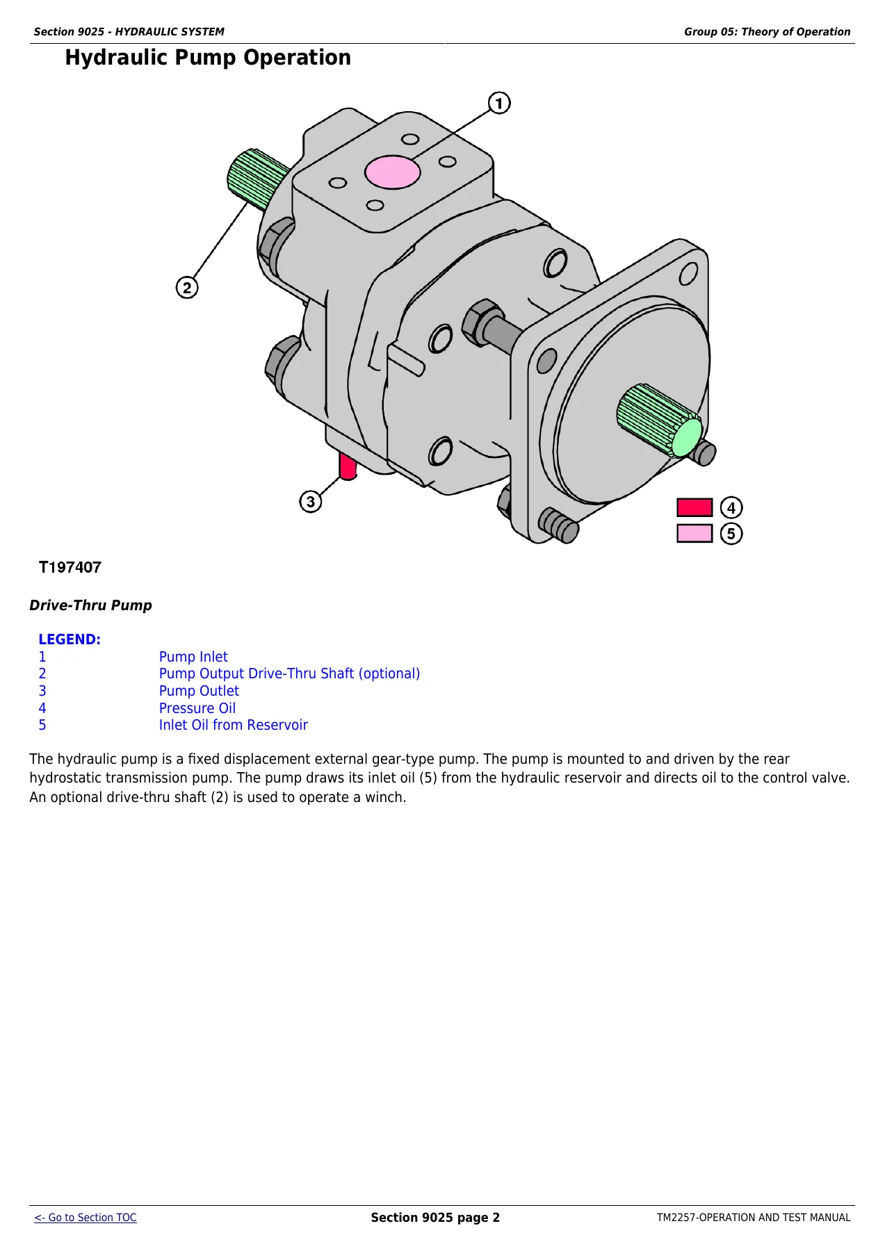
Hydraulic Pump Operationp. 187
Hydraulic Pump and Reservoir Operationp. 188
Hydraulic Filter Operationβ€”Normalp. 190
Hydraulic Filter Operation Continuedβ€”Restrictedp. 191
Control Valve Operationp. 192
System Relief Valve (S.N. β€”108980) And Blade Angle Circuit Relief Valve Operationp. 193
System Relief Valve (S.N. 108981β€” )p. 194
Inlet Valve Operationp. 196
Auxiliary Valve Operationp. 197
Blade Lift Valve Operationp. 199
Blade Angle Valve Operationp. 201
Blade Tilt Valve Operationp. 203
Outlet Valve Cover Operationp. 205
Hydraulic Cylinder Operationp. 206
Group 15 – Diagnostic Informationp. 207
Hydraulic System Schematicp. 207
Hydraulic Component Locationp. 209
Diagnose Hydraulic Systemp. 214
Group 20 – Adjustmentsp. 217
Hydraulic Control Lever Linkage Adjustmentp. 217
Auxiliary Lever Linkage Adjustmentp. 219
Blade Pitch Linkage Adjustmentp. 220
Group 25 – Testsp. 222
Hydraulic Oil Warm-Up Procedurep. 222
Hydraulic Pump Flow Testp. 223
Hydraulic System Relief Valve Testp. 226
Circuit Relief Valve Testβ€”With Remote Pumpp. 229
Hydraulic Pump Cycle Time Testp. 231
Lift Cylinder Drift Testp. 233
Cylinder Leakage Testp. 234
Oil Clean-up Procedurep. 236
Section 9026 – HYDROSTATIC SYSTEMp. 245
Group 05 – Theory of Operationp. 245
Hydrostatic Systemp. 245
Transmission Control Circuitβ€”Flow Chartp. 246
Charge Pump Operationp. 248
Hydrostatic Filter Operationp. 249
Neutral Charge Relief Valve Operationp. 252
Park Brake Operationp. 253
Multi-Function Valve Operationp. 256
Oil Cooler Bypass Valve Operationp. 258
Pump Pressure Control Pilot (PCP) Operationp. 259
Pump Displacement Control Valve (PDCV) Operationp. 261
Hydrostatic Pump Operationp. 263
Flushing Valve and Operating Charge Relief Valve Operationp. 264
Hydrostatic Motor Operationp. 265
Group 15 – Diagnostic Informationp. 267
Hydrostatic Schematicβ€”Neutral (Park Brake ON)p. 268
Hydrostatic System Component Locationp. 270
Hydrostatic System Diagramβ€”Park Brake On (Neutral)p. 275
Hydrostatic System Diagramβ€”Forward (Slow Speed)p. 277
Hydrostatic System Diagramβ€”Reverse (Fast Speed)p. 279
Overheating – Flow Chartp. 281
High/Low Charge Pressure – Flow Chartp. 283
Mistrack/Indexes – Flow Chartp. 285
Machine Will Not Reach Full Speed – Flow Chartp. 287
Low Power – Flow Chartp. 289
TCU Wonβ€²t Calibrate And One Of The Following Codes Are Displayed During Calibration – Flow Chartp. 291
Group 25 – Testp. 293
JT05800 Digital Thermometer Installationp. 293
Digital Pressure And Temperature Analyzer Installationp. 293
Hydraulic Oil Cleanup Procedurep. 294
JDG1770 Ultra Clean Ultra Clean is a trademark of Ultra Clean Technologies Corp. Hand Launcherp. 294
Transmission Oil Warm-Up Procedurep. 295
Releasing Park Brake to Tow the Machinep. 298
Hydrostatic Pump and Motor Initial Start-Up Procedurep. 302
Hydrostatic Pump Flushing Procedurep. 305
Pressure Control Pilot (PCP) Manual Override Testp. 307
Pressure Control Pilot (PCP) Testp. 310
Pressure Control Pilot (PCP) Internal Adjustmentp. 314
Multi-Function Relief Valve Testp. 317
Transmission Efficiency Testp. 322
Neutral Charge Relief and Operating Charge Relief Pressure Testp. 327
Pump Displacement Control Valve (PDCV) Neutral (Null) Adjustmentp. 330
Pump Servo Pressure Testp. 334
Hydrostatic Motor Min./Max. Angle Servo Piston Pressure Testp. 338
Hydrostatic Motor Min. Angle Stop Adjustmentp. 341
Charge Pump Flow Testp. 346
Cooler Bypass Valve Testp. 349
Section 9031 – HEATING AND AIR CONDITIONINGp. 354
Group 05 – Theory of Operationp. 354
Air Conditioner System Cycle Of Operationp. 354
Group 15 – Diagnostic Informationp. 356
Diagnose Air Conditioning System Malfunctionsp. 356
Diagnose Heater System Malfunctionsp. 357
Group 25 – Testp. 358
Proper Refrigerant Handlingp. 358
R134a Refrigerant Cautionsp. 358
R134a Oil Charge Capacityp. 358
R134a Refrigerant Charge Capacityp. 359
Refrigerant Hoses And Tubing Inspectionp. 359
Operating Pressure Diagnostic Chartp. 360
Air Conditioner Low Pressure Switch Test (S.N. β€”102598)p. 362
Air Conditioner High Pressure Switch Test (S.N. β€”102598)p. 364
Air Conditioner High/Low Pressure (Binary) Switch Test (S.N. 102599β€” )p. 366
Freeze Control Switch Testp. 367
Leak Testingp. 368

This John Deere 450J 550J 650J diagnostic manual is organized to move a technician from symptom to solution efficiently. The operational checkout procedure walks through engine-off and engine-on checks, from radiator cap and coolant condition to fan belt tension, start aid operation, fuel system checks, track sag and roller leakage, seat controls, neutral start switch function, wiper and heater blower operation, and more. The engine section covers the PowerTech 4.5L and 6.8L diesel engines with the Level 12 electronic fuel system and Stanadyne DE10 pump, including slow and fast idle tests, fuel system pressure testing, and turbocharger boost pressure testing with model-specific minimum boost pressure specifications. The electrical system section provides system functional schematics, wiring diagrams, component location diagrams, fuse and relay specifications, controller area network (CAN) theory, engine control unit (ECU), monitor display unit (MDU), and transmission control unit (TCU) circuit theory of operation, plus diagnostic trouble code access and calibration procedures. The hydraulic system section covers the open-center hydraulic system, gear pump operation, control valve sections, relief valve operation, cylinder operation, hydraulic pump flow test, system relief valve test, circuit relief valve test, cycle time test, cylinder drift and leakage tests, and the oil clean-up procedure. The hydrostatic system section is especially deep, covering the dual-path hydrostatic drive, charge pump operation, hydrostatic filter, neutral charge relief valve, park brake operation, multi-function valve operation, oil cooler bypass valve, pressure control pilot (PCP) operation, pump displacement control valve (PDCV) operation, hydrostatic pump and motor operation, flushing valve and operating charge relief valve, plus diagnostic flow charts for overheating, high/low charge pressure, mistrack/indexes, machine will not reach full speed, and low power. Test procedures include the transmission oil warm-up procedure, releasing park brake to tow, hydrostatic pump and motor initial start-up, hydrostatic pump flushing, PCP manual override test, PCP test and internal adjustment, multi-function relief valve test, transmission efficiency test, neutral charge relief and operating charge relief pressure test, PDCV neutral (null) adjustment, pump servo pressure test, hydrostatic motor min./max. angle servo piston pressure test, hydrostatic motor min. angle stop adjustment, charge pump flow test, and cooler bypass valve test. The heating and air conditioning section covers the A/C system cycle of operation, diagnostic information for both A/C and heater systems, proper refrigerant handling, R134a oil and refrigerant charge capacities, operating pressure diagnostic chart, low pressure switch test, high pressure switch test, high/low pressure (binary) switch test, freeze control switch test, and leak testing.

What This Manual Does for You

If you own or service a 450J, 550J, or 650J crawler dozer, this John Deere diagnostic operation and test manual is the difference between guessing and knowing. It provides the exact test procedures and specifications to diagnose engine performance complaints, isolate electrical faults using the CAN and controller theory, verify hydraulic pump and valve performance, and confirm hydrostatic transmission health before a major repair. The diagnostic flow charts take you step by step from a symptom to the likely cause, saving hours of trial-and-error. The TCU calibration procedure, diagnostic trouble code tables, and component specifications give you the reference data you need to bring the machine back to factory operating condition.

IMAGES PREVIEW

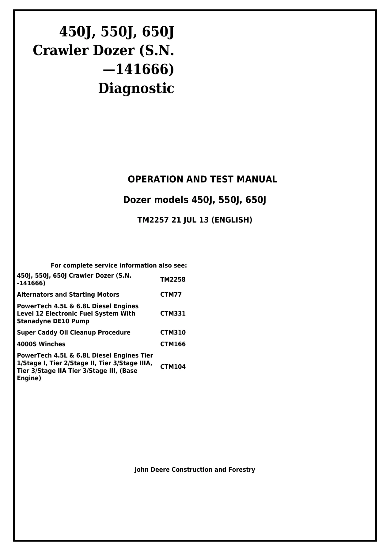
John Deere 450J 550J 650J Crawler Dozer Diagnostic Operation and Test Manual TM2257 - PDF Download β€” PDF page 1 preview
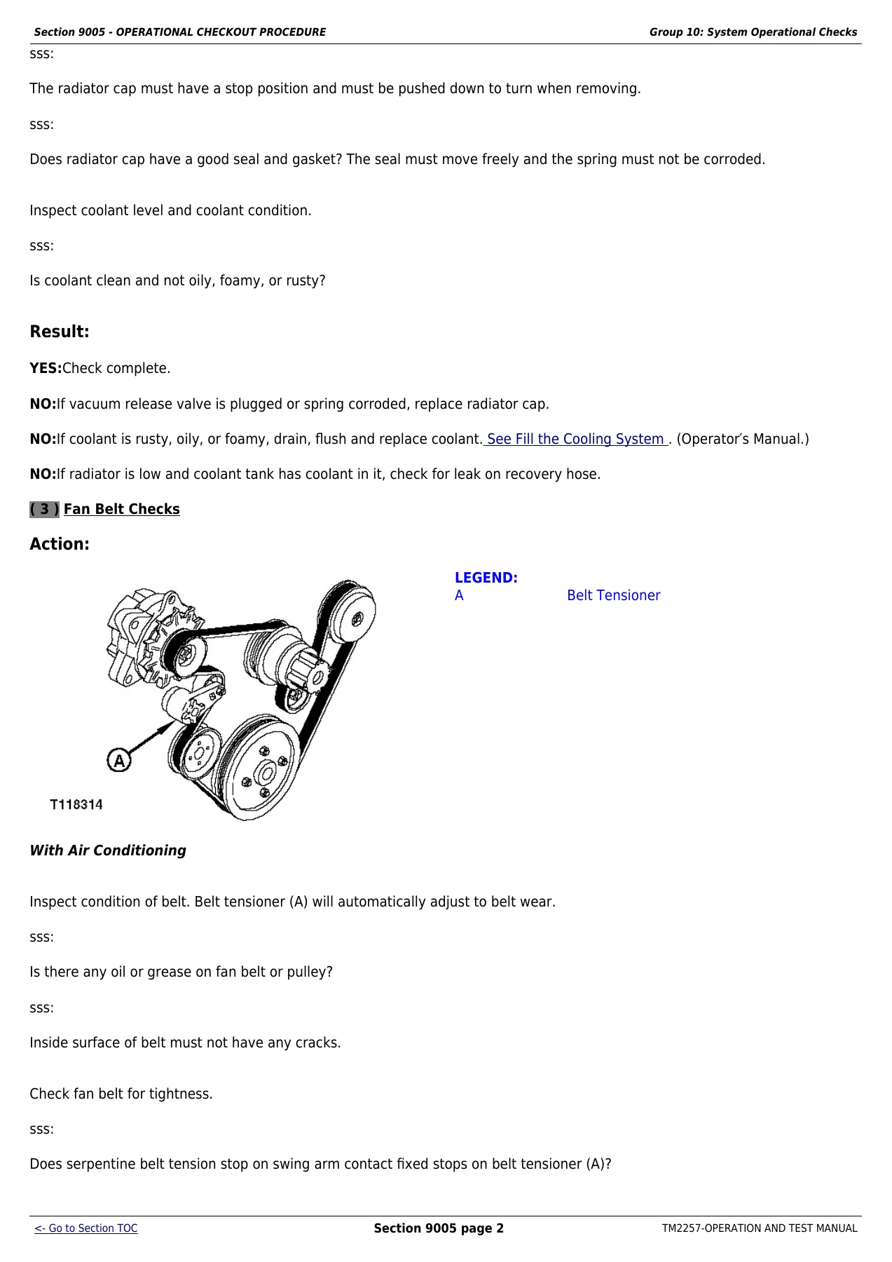
John Deere 450J 550J 650J Crawler Dozer Diagnostic Operation and Test Manual TM2257 - PDF Download β€” PDF page 24 preview
John Deere 450J 550J 650J Crawler Dozer Diagnostic Operation and Test Manual TM2257 - PDF Download β€” PDF page 187 preview

Instant PDF delivery. No shipping, no waiting. Download the TM2257 manual immediately after payment and access it on any device β€” laptop in the shop, tablet in the field, or printed copy for the bench. The PDF format lets you zoom into wiring diagrams, print specific pages for the job, and keep the entire diagnostic resource at your fingertips.
Reviews

There are no reviews yet.

Be the first to review “John Deere 450J 550J 650J Crawler Dozer Diagnostic Operation and Test Manual TM2257 – PDF Download”

What Our Customers Say

β˜…β˜…β˜…β˜…β˜… Live reviews from customers
Loading customer reviews...
0
    0
    Your Cart
    Your cart is emptyReturn to Shop
    πŸ›’
    Recently Purchased
    πŸ•’ verified order