John Deere TerrainCut 1550 1570 1575 1580 1585 Technical Manual TM130419 PDF
$49.95 Original price was: $49.95.$29.95Current price is: $29.95.
Complete John Deere TerrainCut 1550, 1570, 1575, 1580, and 1585 Series front mower technical manual TM130419. Covers engine repair, electrical systems, power train, hydraulics, steering, brakes, attachments, cab, and HVAC with detailed procedures, specifications, and diagnostics. Instant PDF download.
Description
John Deere TerrainCut 1550 1570 1575 1580 1585 Series Technical Manual TM130419
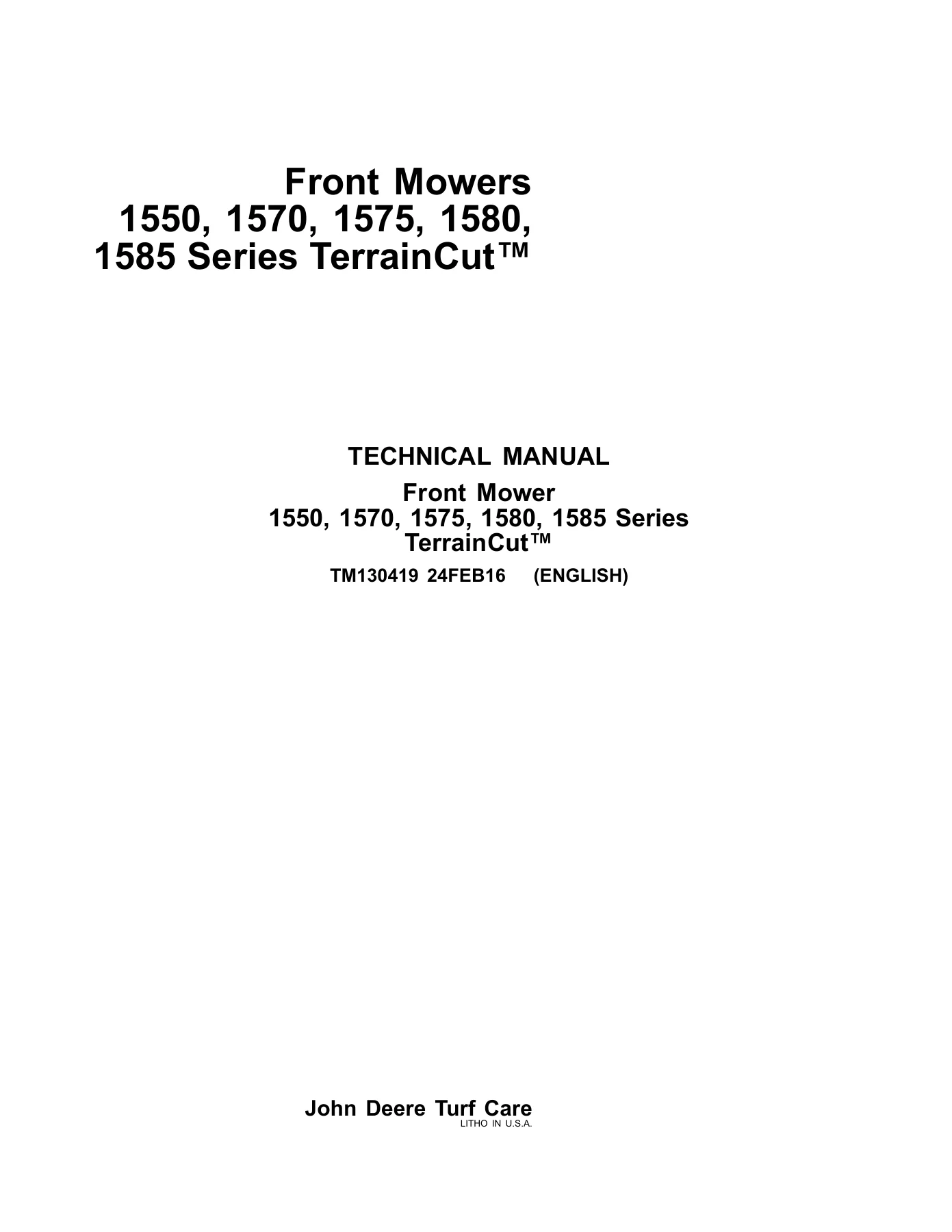
This is the complete John Deere TerrainCut 1550, 1570, 1575, 1580, and 1585 Series technical manual, document number TM130419, published 24FEB16 in English. It is a full workshop-level service reference covering engine, electrical, power train, hydraulic, steering, brake, attachment, cab, and HVAC systems across all five TerrainCut front mower models.
File Details
- Manual Type: Technical Manual (Repair, Operation, Tests & Adjustments)
- Brand: John Deere
- Models Covered: 1550, 1570, 1575, 1580, 1585 Series TerrainCut
- Document Number: TM130419
- Publication Date: 24FEB16
- Language: English
- File Format: PDF
- Page Count: 1340 pages
Chapters Covered
The manual is organized into sections that mirror the machine’s major systems, each containing repair procedures and separate operation, test, and adjustment groups.
- Section 05 β Safety: Safety information, signal words, safety signs, fluid handling, emergency preparation, battery explosion prevention, acid burn prevention, protective clothing, high-pressure fluid hazards, proper tools, safe parking, proper support, lifting equipment, clean work areas, high-pressure washers, work area illumination, ventilation, California Proposition 65, paint removal before welding, asbestos dust, tire recommendations, rotating driveline safety, cooling system safety, waste disposal, chemical product handling, live with safety
- Section 10 β Specifications and Information: General information (metric bolt and screw torque values, unified inch bolt and screw torque values, O-ring boss fittings, flat face O-ring seal fittings, STC fittings, proper fuel, engine oil, hydrostatic transaxle oil, 4WD rear axle oil, grease, engine coolant), fuels/lubricants/coolants (diesel fuel, handling and storing diesel fuel, galvanized containers, lubricity, testing diesel fuel, BioDiesel fuel, filling fuel tank, engine oil, oil filters, transmission and hydraulic oil, correct transmission/hydraulic filter element, MFWD axle housing and wheel hub oil, grease, mixing lubricants, alternative and synthetic lubricants, lubricant storage, operating in warm temperature climates, diesel engine coolant, John Deere COOL-GARD II coolant extender, testing diesel engine coolant), machine specifications
- Section 20 β Engine Repair: Engine repair for 3TNV80F, 3TNV82A, 3TNV88, and 3TNV88C. Covers rocker arm cover, rocker arm assembly, cylinder head and valves, exhaust and intake manifolds, valve seats, fuel injection pump, fuel injection nozzles, fuel shutoff solenoid, electric fuel pump, pistons and connecting rods, cylinder bore, crankshaft oil seals, crankshaft and main bearings, flywheel, camshaft, timing gears, oil pan and strainer, oil pump, thermostat, coolant temperature switch, water pump
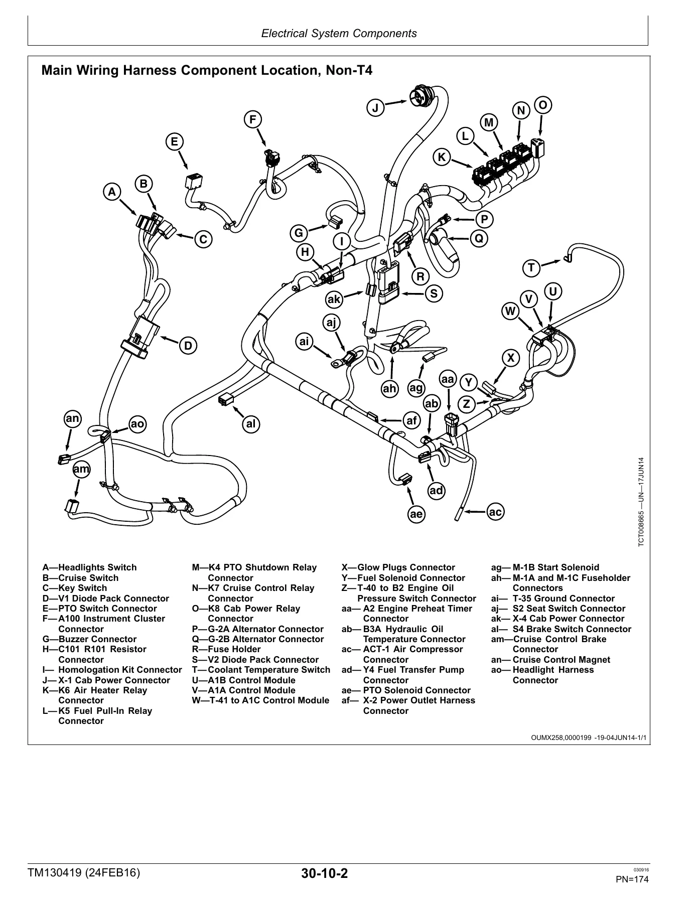
- Section 30 β Electrical Repair: Electrical system components, wiring harnesses, repair. Battery, alternator, starting motor removal, installation, and repair. Component location for instrument cluster, main wiring harness (Non-T4 and T4), upper cab wiring harness, cab relays, lower cab wiring harness
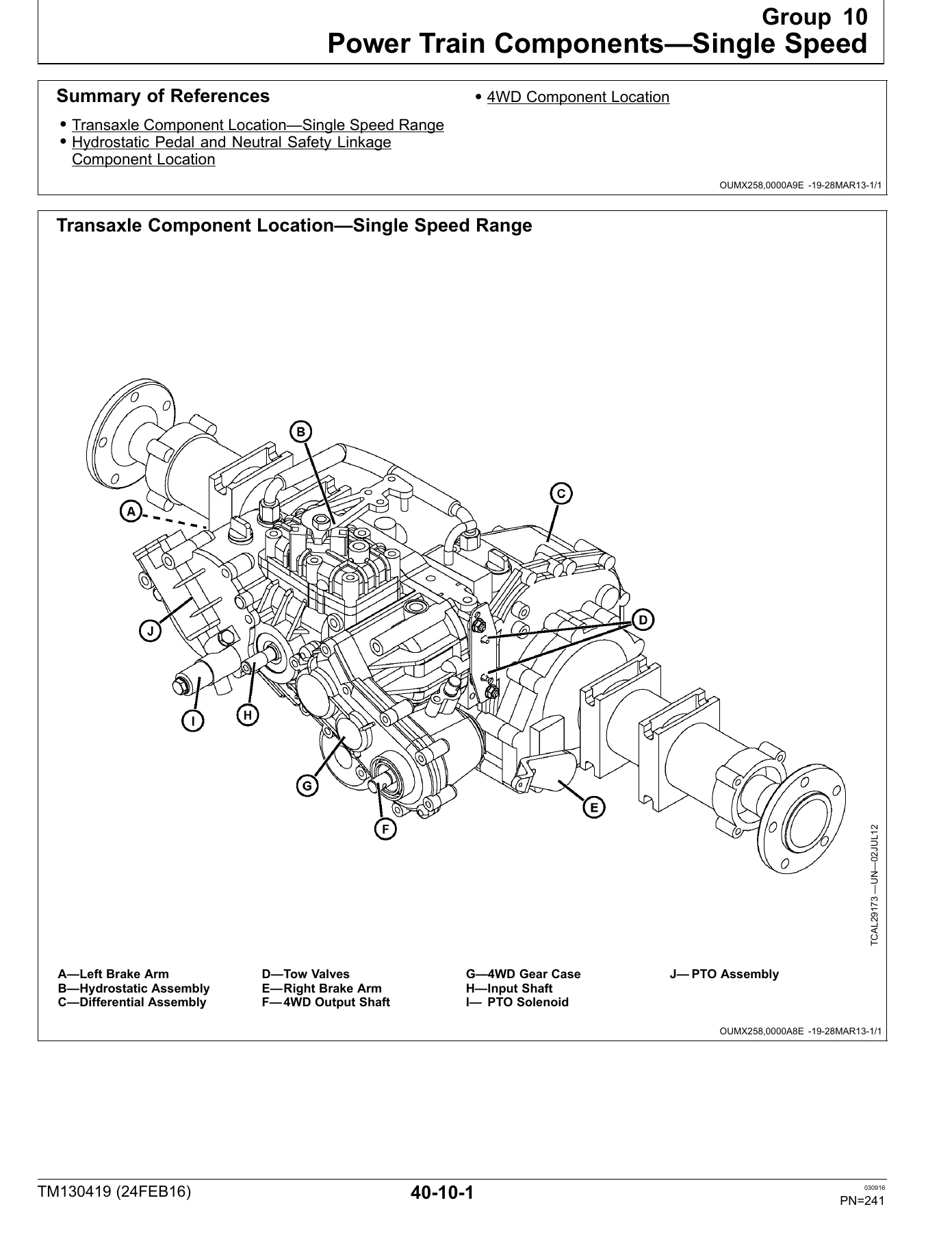
- Section 40 β Power Train Repair: Power train components for single speed and 2 speed transaxles, 4WD component location, engine driveshaft, transaxle removal and installation, hydrostatic and differential assembly separation, charge pump disassembly/inspection/assembly, hydrostatic assembly, differential assembly, PTO, 4WD drive shaft, 4WD gear case, 4WD axle
- Section 50 β Hydraulics Repair: Component location, hydraulic system component location, auxiliary hydraulic kit component location, steering system hydraulic hose routing, weight transfer system component location, lift system hydraulic hose routing. Oil cooler, lift lever, implement lift valve, lift cylinder, auxiliary hydraulic valve, hydraulic pump
- Section 60 β Steering and Brakes Repair: Steering system component location, steering column repair kit, steering cylinder, brake linkage, turn brake pedals, master brake pedal, park brake lock lever assembly
- Section 70 β Attachments Repair: Cutting units (rotating mower decks, belt shields, drive belts, vertical belt drive alignment, blades, spindles, drive shafts, gearboxes, caster wheels), snowblowers (gear case inspection, gear assembly, main case inspection/assembly, rotor and fan installation, fan/coupler replacement, rotor bearing replacement), GLC system (collection system removal/installation, hydraulic pump to deck, blower fan drive belt, suction port, blower hose)
- Section 80 β Cab Repair: Headliner, outer roof, cab air filter, cab door, cab removal and installation
- Section 90 β Miscellaneous Repair: Right side panel, fuel tank
- Section 220 β Engine Operation, Tests, and Adjustments: Theory of operation (engine information, cooling system, lubrication system, fuel and air system), diagnosis for 3TNV80 (engine will not start, starts but does not continue running, low engine output, exhaust color, high exhaust temperature, runs rough, excessive fuel/oil consumption, fuel oil in crankcase, coolant in crankcase, low oil pressure, overheating, low coolant temperature, low compression, starter issues), diagnosis for 3TNV82A/3TNV88 (engine will not start), tests and adjustments for 3TNV80F (alternator belt tension, valve clearance, valve lift, cylinder compression, engine oil pressure, fuel system leak test, priming, slow idle speed, throttle cable, fuel injection system, fuel injection nozzle, injection pump static timing, cooling system pressure test, radiator cap, thermostat, cylinder leakdown, fuel transfer pump pressure/flow), tests and adjustments for 3TNV82A/3TNV88 (fan/alternator belt, cylinder compression, slow idle, throttle cable, injection pump static timing, valve clearance, fuel injection nozzle, thermostat, cylinder pressure leakage, cooling system pressure, radiator pressure cap, oil pressure, fuel pump pressure, fuel transfer pump flow, fuel system leakage, priming)
- Section 230 β Electrical Operation, Tests, and Adjustments: Theory of operation for Non-T4 (unswitched power, switched power, cranking, charging, operator presence and PTO interlock, engine oil pressure light and buzzer, engine coolant temperature light and buzzer, hydraulic oil temperature light, cold start, fuel shutoff solenoid, cruise control) and Tier 4 (unswitched power, switched power, cranking, charging, operator presence and PTO interlock, engine oil pressure, engine coolant temperature, hydraulic oil temperature, cold start, cruise control, CAN bus), schematics, diagnosis, tests and adjustments (battery, key switch, beacon light switch, relay, glow plug, air preheater, diode pack, headlight switch, turn signal switch, rotary light switch, rotary blower switch, cruise control switch, cruise brake switch, wiper switch, diode, fuse, A/C switch, A/C temperature control switch, dome light switch, door switch, PTO switch, park brake switch, PTO solenoid, hydraulic temperature switch, engine oil pressure switch, coolant temperature switch, fuel pump, fuel shutoff solenoid, cruise control magnet, seat switch, warning alarm, DPF sensors, accelerator sensor)
- Section 235 β Controllers Operation, Tests, and Adjustments: Adjustments (approved software for control units, service timer menu, display setup screens, Service ADVISOR based calibrations), DPF functions and DTCs (exhaust filter system overview, understanding DPF regeneration, DPF regeneration indicators, accessing DPF displays, DPF operator display, active regeneration, inhibiting active regeneration, parked regeneration, parked regeneration interlocks, recovery regeneration, DPF status screens, DPF load level, Tier 4 warning popups, aftertreatment verification procedure, DOC calibration, DPF calibration), set up PDU (main screens navigation, language select, text selection, machine status screens, active DTC flow description, stored DTC flow description, pass codes, machine start pass code entry, display setup screen detailed, version information, reprogramming), theory of operation (CAN bus message structure, CAN bus operation, data bus systems, CAN trace, DTCs overview, PDU, hour meter), checks/tests/procedures (diagnostic tools, CAN message not received, CAN message received error, CAN message received is incorrect, terminal test, verification procedure, wiggle test, short to voltage procedure, problem not found procedure, accessing addresses and DTCs, CAN communication fault checks, CAN bus terminator test, control unit messaging errors, CAN network voltage checks, erroneous DTCs, troubleshooting electronic control units, diagnostic information, readings overview, VCU readings, PDU I-O status readings, ECU data points, electronic injector calibration, Service ADVISOR based tests), diagnose DTCs for PDU and VCU and ECU (start interlock violations, run interlock screen, service required, coolant over temp, park brake off and attempting to crank engine, crank time exceeded warning, crank time exceeded warning delay, PTO engaged and operator out of seat, hydraulic oil over temp, charge system failure low, low oil pressure, filter cleaning required, parked cleaning required, ash clean required, park brake not engaged and attempting to activate parked regeneration, charge system failure high, park brake engaged not mowing, PTO engaged not mowing, PTO engaged and attempting to activate parked regeneration, parked cleaning stopped, engine oil service, hydraulic oil service, engine stop, engine warning, machine general warning fault, machine general info fault, VCU DTC quick reference table, VCU DTCs, ECU DTCs 000001-000199, 000200-000699, 000700-001999, 002000-002999, 003000-003999, 004000-529999)
- Section 240 β Power Train Operation, Tests, and Adjustments: Diagnosis for single speed (differential will not lock, machine moves with pedals in neutral, machine will not move when pedals pressed, machine will not reach full speed, PTO turns with switch off, PTO shaft will not turn, rear wheels do not drive) and 2 speed (same categories). Tests and adjustments for single speed (transaxle neutral creep, F-N-R linkage, differential lock, 4WD axle pivot pin clearance) and 2 speed (transaxle neutral creep, F-N-R linkage, differential lock, 4WD axle pivot pin clearance)
- Section 250 β Hydraulics Operation, Tests, and Adjustments: Theory of operation (hydraulic system, lift circuit, auxiliary hydraulic, GLC circuit), schematics (main hydraulic without auxiliary valve, main hydraulic with auxiliary valve, single spool auxiliary kit, double spool auxiliary kit, GLC hydraulic), diagnosis (lift system, auxiliary hydraulic, weight transfer), tests and adjustments (hydraulic oil warm-up, hydraulic system bleeding, charge pressure relief valve, hydraulic pump flow and implement relief valve, PTO solenoid valve, PTO relief valve, MCS600 Plus)
- Section 260 β Steering and Brakes Operation, Tests, and Adjustments: Theory of operation (steering neutral, power turn, manual turn, brake system), steering diagnosis (high steering effort, hydraulic oil foams, lost motion, machine continues to turn, sluggish response, steering not driving straight, steering operation reversed, steering wheel vibration), brakes diagnosis (machine will not move, brake will not engage, excessive brake wear, machine pulls to one side), tests and adjustments (steering toe-in, steering system leakage, steering valve leakage, turn brake, brake switch)
- Section 270 β Attachments Operation, Tests, and Adjustments: Diagnosis for 60/62/72-inch mower decks (linkage, deck level, drive belt, tension spring, adjustment arm, spindle sheave, spindle and housing, blades, caster wheels, caster wheel yoke assemblies, engine, PTO shaft), 7-Iron V-Flex deck (linkage, deck level, drive belt, vertical drive belts, tension springs, spindle sheave, spindle and housing, blades, caster wheels, caster wheel yoke assemblies), 60-inch heavy-duty snowblower (auger drive system, spout control system), GLC system (suction system, suction capacity, turbine vibration, turbine noise, turbine does not run, material escapes between shells, material escapes between blow-in port and shell). Tests and adjustments (mower deck level, V-Flex deck level, mower drive belt tension, V-Flex deck drive belt tension, blower fan drive belt, hopper hinges, cover closing force, blow-in port seal, cover seal compression, blower blade balancing)
- Section 280 β Cab Operation, Tests, and Adjustments: Operator station controls for 1575 and 1585 cab models
- Section 290 β HVAC Operation, Tests, and Adjustments: Tools and materials, general information (system information, refrigerant oil information, determining correct refrigerant oil charge), tests and adjustments (air conditioner specifications, heater temperature control cable, A/C temperature control switch cable, compressor shaft seal leakage test, compressor clutch hub clearance check, evaporator/heater core leak test, compressor oil charge check, adding refrigerant oil to system, recover/recycle refrigerant, air conditioning receiver/dryer, A/C compressor belt tension)
- Section 299 β Tools and Kits: Service equipment and tools, Tier 4 engine essential or recommended tools
This technical manual gives a technician the complete factory service information for the TerrainCut 1550 through 1585 series. It is not a generic overview β it is the same structured repair and diagnostic content used to service these machines in the field. The engine repair section alone spans three distinct Yanmar engine platforms, with each covered from rocker cover removal down to crankshaft and main bearing inspection. The electrical section includes both Non-T4 and Tier 4 wiring schematics, component locations, and connector pinouts. The controller section adds CAN bus diagnostics, DPF regeneration procedures, and hundreds of pages of diagnostic trouble code troubleshooting for the VCU, PDU, and ECU.
Complete Bookmarks
The complete bookmarks in the βJohn Deere TerrainCut 1550 1570 1575 1580 1585 Technical Manual TM130419 PDFβ are as follows:
+Contentsp. 3
+Safetyp. 5
+Safetyp. 7
+Specifications and Informationp. 17
+General Informationp. 19
+Fuels, Lubricant, and Coolantsp. 27
+Machine Specificationsp. 37
+Engine Repairp. 40
+Engine Repairβ3TNV80Fp. 41
+Engine Repairβ3TNV82A, 3TNV88p. 101
+Engine Repairβ3TNV88Cp. 161
+Electrical Repairp. 171
+Electrical System Componentsp. 173
+Wiring Harnessesp. 179
+Repairp. 223
+Power Train Repairp. 239
+Power Train ComponentsβSingle Speedp. 241
+Power Train Componentsβ2 Speedp. 245
+Power Train RepairβSingle Speedp. 249
+Power Train Repairβ2 Speedp. 347
+Hydraulics Repairp. 467
+Component Locationp. 469
+Repairp. 475
+Steering and Brakes Repairp. 489
+Component Locationp. 491
+Steering Repairp. 493
+Brakes Repairp. 495
+Attachments Repairp. 505
+Repair, Cutting Unitsp. 507
+Repair, Snowblowersp. 547
+Repair, GLC Systemp. 563
+Cab Repairp. 577
+Repairp. 579
+Miscellaneous Repairp. 587
+Repairp. 589
+Engine Operation, Tests, and Adjustmentsp. 596
+Theory of Operationp. 597
+Diagnosisβ3TNV80p. 599
+Diagnose Engine Will Not Startp. 599
+Diagnose Engine Starts But Does Not Continue Running – No Exhaust Smokep. 601
+Diagnose Engine Starts But Does Not Continue Running – Excessive Exhaust Smokep. 602
+Diagnose Low Engine Output – Normal Exhaust Colorp. 604
+Diagnose Low Engine Output – White Exhaust Colorp. 605
+Diagnose Low Engine Output – Black Exhaust Colorp. 606
+Diagnose Exhaust Color White Under Loadp. 608
+Diagnose Exhaust Color Black Under Loadp. 610
+Diagnose High Exhaust Temperaturep. 611
+Diagnose Engine Runs Rough – Misfiringp. 613
+Diagnose Engine Runs Rough – Uneven Combustion Soundp. 614
+Diagnose Engine Runs Rough – Surges During Idlep. 616
+Diagnose Engine Runs Rough – Surges Under Loadp. 617
+Diagnose Engine Runs Rough – Excessive Vibrationp. 617
+Diagnose Excessive Fuel Consumptionp. 618
+Diagnose Excessive Oil Consumptionp. 619
+Diagnose Fuel Oil in Crankcasep. 620
+Diagnose Coolant in Crankcasep. 621
+Diagnose Low Oil Pressurep. 622
+Diagnose Engine Overheatingp. 623
+Diagnose Low Engine Coolant Temperaturep. 624
+Diagnose Low Compressionp. 624
+Diagnose Starter Motor Does Not Rotatep. 625
+Diagnose Starter Rotates Slowlyp. 626
+Diagnose Starter Rotates But Does Not Crankp. 627
+Diagnosisβ3TNV82A, 3TNV88p. 629
+Engine Will Not Startp. 629
+Tests and Adjustmentsβ3TNV80Fp. 633
+Tests and Adjustmentsβ3TNV82A, 3TNV88p. 651
+Electrical Operation, Tests, and Adjustmentsp. 672
+Theory of Operation, Non-T4p. 673
+Theory of Operation, Tier 4p. 699
+Schematicsp. 725
+Diagnosisp. 761
+Power Circuit Diagnosis, Non-T4p. 761
+Tests and Adjustmentsp. 763
+Connectorsp. 787
+Controllers Operation, Tests, and Adjustmentsp. 809
+Adjustmentsp. 811
+DPF Functions and DTCsp. 817
+Set Up, PDUp. 835
+Theory of Operationp. 847
+Checks, Tests, and Proceduresp. 851
+Verification Procedurep. 857
+Short to Voltage Procedurep. 859
+Problem Not Found Procedurep. 860
+DiagnoseβDTCs, PDUp. 875
+DiagnoseβDTCs, VCUp. 883
+VCU 000070.14 β Park Brake Switchp. 885
+VCU 000158.01 β Switched Power Faultp. 886
+VCU 000168.00 β Supply Voltage (VBAT) Faultp. 887
+VCU 000168.01 β Supply Voltage (VBAT) Faultp. 888
+VCU 000168.16 β Supply Voltage (VBAT) Faultp. 889
+VCU 000168.18 β Supply Voltage (VBAT) Faultp. 890
+VCU 000595.03 β Cruise Control Switch Short to Highp. 891
+VCU 000595.04 β Cruise Control Short to Lowp. 892
+VCU 000629.12 β Watch Dog Time Outp. 893
+VCU 000931.03 β Fuel Pump Short to Highp. 897
+VCU 000931.04 β Fuel Pump Short to Lowp. 898
+VCU 001504.31 β Out of Neutral and Out of Seatp. 899
+VCU 001638.00 β Hydraulic Oilp. 900
+VCU 003509.03 β Sensor Power Supply Highp. 901
+VCU 003509.04 β Sensor Power Supply Lowp. 902
+VCU 516124.03 β Engine Run Request Short to Highp. 904
+VCU 516124.04 β Engine Run Request Short to Lowp. 905
+VCU 516200.03 β PTO Low Side Driverp. 906
+VCU 516200.04 β PTO Low Side Driverp. 907
+VCU 516206.03 β PTO High Side Driverp. 908
+VCU 516206.04 β PTO High Side Driverp. 908
+VCU 516206.05 β PTO High Side Driverp. 909
+VCU 516399.03 β Auxiliary (Cab) Relay Driver Short to Highp. 910
+VCU 516399.04 β Auxiliary (Cab) Power Relay Driver Short to Lowp. 911
+VCU 520870.31 β EEPROM Checksum Failp. 912
+VCU 520871.31 β EEPROM Non Critical Data Checksum Failp. 912
+VCU 520872.31 β EEPROM Critical Data Checksum Failurep. 913
+VCU 520873.31 β EEPROM Vehicle Hours Data Checksum Failurep. 914
+VCU 524265.31 β EOL Checksum Failurep. 915
+DiagnoseβDTCs, ECU 000001β000199p. 917
+ECU 000028.00 β Analog Throttle Signal Extremely Highp. 917
+ECU 000028.01 β Analog Throttle Signal Extremely Lowp. 918
+ECU 000028.03 β Analog Throttle Signal Out of Range Highp. 919
+ECU 000028.04 β Analog Throttle Out of Range Lowp. 920
+ECU 000051.03 β Air Throttle Actuator Position Signal Out of Range Highp. 921
+ECU 000051.04 β Air Throttle Actuator Position Signal Out of Range Lowp. 923
+ECU 000100.01 β Engine Oil Pressure Signal Extremely Lowp. 926
+ECU 000100.04 β Engine Oil Pressure Signal Out of Range Lowp. 928
+ECU 000102.03 β Manifold Air Pressure Signal Out of Range Highp. 930
+ECU 000102.04 β Manifold Air Pressure Signal Out of Range Lowp. 933
+ECU 000102.13 β Manifold Air Pressure Signal Calibration Faultp. 936
+ECU 000105.03 β Manifold Air Temperature Signal Out of Range Highp. 939
+ECU 000105.04 β Manifold Air Temperature Signal Out of Range Lowp. 941
+ECU 000108.03 β Barometric Pressure Signal Out of Range Highp. 943
+ECU 000108.04 β Barometric Pressure Signal Out of Range Lowp. 944
+ECU 000108.10 β Barometric Pressure Signal Abnormalp. 945
+ECU 000110.00 β Engine Coolant Temperature Signal Extremely Highp. 946
+ECU 000110.03 β Engine Coolant Temperature Signal Out of Range Highp. 948
+ECU 000110.04 β Engine Coolant Temperature Signal Out of Range Lowp. 950
+ECU 000157.00 β Fuel Rail Pressure Signal Extremely Highp. 952
+ECU 000157.03 β Fuel Rail Pressure Signal Out of Range Highp. 955
+ECU 000157.04 β Fuel Rail Pressure Signal Out of Range Lowp. 957
+ECU 000157.15 β Fuel Rail Pressure Signal Slightly Highp. 959
+ECU 000157.16 β Fuel Rail Pressure Limiter Openp. 962
+ECU 000157.18 β Fuel Rail Pressure Signal Moderately Lowp. 965
+ECU 000167.01 β Charging System Voltage Extremely Lowp. 968
+ECU 000167.05 β Charging System Circuit Out of Range Lowp. 969
+ECU 000173.03 β Exhaust Manifold Temperature Signal Out Of Range Highp. 970
+ECU 000173.04 β Exhaust Manifold Temperature Signal Out Of Range Lowp. 972
+ECU 000174.00 β Fuel Temperature Signal Extremely Highp. 974
+ECU 000174.03 β Fuel Temperature Signal Out Of Range Highp. 976
+ECU 000174.04 β Fuel Temperature Signal Out Of Range Lowp. 978
+ECU 000190.00 β Engine Speed Extremely Highp. 980
+DiagnoseβDTCs, ECU 000200β000699p. 983
+ECU 000412.03 β EGR Temperature Signal Out of Range Highp. 983
+ECU 000412.04 β EGR Temperature Signal Out Of Range Lowp. 985
+ECU 000630.12 β ECU EEPROM Errorp. 987
+ECU 000633.03 β Suction Control Valve Circuit Out of Range Highp. 988
+ECU 000633.05 β Suction Control Valve Circuit Has High Resistancep. 991
+ECU 000633.06 β Suction Control Valve Circuit Has Low Resistancep. 994
+ECU 000652.03 β Injector #3 Circuit Out of Range Highp. 997
+ECU 000652.05 β Injector #3 Circuit Has High Resistancep. 1000
+ECU 000652.06 β Injector #3 Circuit Has Low Resistancep. 1002
+ECU 000653.03 β Injector #2 Circuit Out of Range Highp. 1005
+ECU 000653.05 β Injector #2 Circuit Has High Resistancep. 1008
+ECU 000653.06 β Injector #2 Circuit Has Low Resistancep. 1011
+ECU 000654.03 β Injector #1 Circuit Out of Range Highp. 1014
+ECU 000654.05 β Injector #1 Circuit Has High Resistancep. 1016
+ECU 000654.06 β Injector #1 Circuit Has Low Resistancep. 1019
+DiagnoseβDTCs, ECU 000700β001999p. 1023
+ECU 001209.03 β Exhaust Manifold Pressure Signal Out of Range Highp. 1023
+ECU 001209.04 β Exhaust Manifold Pressure Signal Out of Range Lowp. 1025
+ECU 001209.13 β Exhaust Manifold Pressure Signal Calibration Faultp. 1028
+DiagnoseβDTCs, ECU 002000β002999p. 1031
+ECU 002791.00 β EGR Valve Drive Circuit Voltage Extremely Highp. 1031
+ECU 002791.01 β EGR Valve Drive Circuit Voltage Extremely Lowp. 1033
+ECU 002791.07 β EGR Valve Position Errorp. 1036
+ECU 002791.09 β EGR Valve Communication Errorp. 1037
+ECU 002791.12 β EGR Valve Actuator Internal Errorp. 1038
+ECU 002797.06 β Injector High Voltage Supply #1 Circuit Has Low Resistancep. 1039
+ECU 002798.06 β Injector High Voltage Supply #2 Circuit Has Low Resistancep. 1040
+ECU 002950.03 β Air Throttle Actuator Drive Circuit 1 Out of Range Highp. 1041
+ECU 002950.04 β Air Throttle Actuator Drive Circuit 1 Out of Range Lowp. 1043
+ECU 002950.05 β Air Throttle Actuator Drive Circuit Has High Resistancep. 1045
+ECU 002950.06 β Air Throttle Actuator Drive Circuit Has Low Resistancep. 1048
+ECU 002951.03 β Air Throttle Actuator Drive Circuit 2 Out of Range Highp. 1051
+ECU 002951.04 β Air Throttle Actuator Drive Circuit 2 Out of Range Lowp. 1054
+DiagnoseβDTCs, ECU 003000β003999p. 1057
+ECU 003242.00 β DOC Inlet Temperature Extremely Highp. 1057
+ECU 003242.03 β DOC Inlet Temperature Signal Out of Range Highp. 1059
+ECU 003242.04 β DOC Inlet Temperature Signal Out of Range Lowp. 1061
+ECU 003250.00 β DOC Outlet Temperature Extremely Highp. 1063
+ECU 003250.01 β DOC Outlet Temperature Extremely Lowp. 1065
+ECU 003250.03 β DOC Outlet Temperature Signal Out of Range Highp. 1067
+ECU 003250.04 β DOC Outlet Temperature Signal Out of Range Lowp. 1069
+ECU 003251.00 β DPF Differential Pressure Extremely Highp. 1071
+ECU 003251.03 β DPF Differential Pressure Signal Out of Range Highp. 1073
+ECU 003251.04 β DPF Differential Pressure Signal Out of Range Lowp. 1075
+ECU 003251.13 β DPF Differential Pressure Sensor Calibration Faultp. 1077
+ECU 003609.03 β DPF Inlet Pressure Signal Out of Range Highp. 1079
+ECU 003609.04 β DPF Inlet Pressure Signal Out of Range Lowp. 1081
+ECU 003719.00 β Calculated Soot Level Extremely Highp. 1084
+ECU 003719.07 β DPF Recovery Prohibitedp. 1086
+ECU 003719.09 β DPF Recovery Failedp. 1088
+ECU 003719.16 β Calculated Soot Level Moderately Highp. 1090
+ECU 003720.00 β Calculated Ash Level Extremely Highp. 1092
+ECU 003720.16 β Calculated Ash Level Moderately Highp. 1093
+DiagnoseβDTCs, ECU 004000β529999p. 1095
+ECU 004257.12 β Injector High Voltage Supply Internal Failurep. 1095
+ECU 522243.05 β Glow Plug Relay Driver Circuit Has High Resistancep. 1096
+ECU 522243.06 β Glow Plug Relay Driver Circuit Has Low Resistancep. 1097
+ECU 522329.00 β Water-In-Fuel Level Extremely Highp. 1098
+ECU 522400.02 β Crankshaft Position Signal Invalidp. 1101
+ECU 522400.05 β Crankshaft Position Signal Missingp. 1103
+ECU 522401.02 β Camshaft Position Signal Invalidp. 1105
+ECU 522401.05 β Camshaft Position Signal Missingp. 1108
+ECU 522401.07 β Camshaft Position and Crankshaft Position Signals Out of Syncp. 1111
+ECU 522571.03 β Suction Control Valve Low Side Drive Circuit Out of Range Highp. 1114
+ECU 522571.06 β Suction Control Valve Low Side Drive Circuit Has Low Resistancep. 1117
+ECU 522572.06 β Suction Control Valve High Side Drive Circuit Has Low Resistancep. 1120
+ECU 522572.11 β Suction Control Valve High Side Drive Circuit Current Faultp. 1123
+ECU 522573.00 β Calculated Soot Level Highp. 1126
+ECU 522574.00 β DPF Differential Pressure Soot Level Highp. 1127
+ECU 522575.07 β Parked Regeneration Failedp. 1128
+ECU 522576.12 β ECU EEPROM Read Errorp. 1129
+ECU 522578.12 β ECU EEPROM Write Errorp. 1131
+ECU 522579.12 β EGR Valve Actuator Low Resistance Errorp. 1132
+ECU 522580.12 β EGR Valve Position Internal Errorp. 1133
+ECU 522582.07 β EGR Valve Initialization Errorp. 1134
+ECU 522583.01 β EGR Valve Actuator High Temperature Sensor Faultp. 1136
+ECU 522584.01 β EGR Valve Actuator Low Temperature Sensor Faultp. 1137
+ECU 522585.12 β ECU Internal Fault 17p. 1138
+ECU 522588.12 β ECU Internal Voltage High Errorp. 1139
+ECU 523489.12 β ECU Internal Voltage Low Errorp. 1140
+ECU 522591.12 β Sensor Supply #2 Voltage Errorp. 1141
+ECU 522592.12 β Sensor Supply #3 Voltage Errorp. 1144
+ECU 522610.09 β EGR Valve CAN Communication Errorp. 1150
+ECU 522617.12 β EGR Valve Position Mismatchp. 1151
+ECU 522744.04 β ECU Power Supply Output #1 Circuit Has Low Resistancep. 1153
+ECU 522994.04 β ECU Power Supply Output #2 Circuit Has Low Resistancep. 1154
+ECU 523249.05 β Crankshaft Position and Camshaft Position Signals Invalidp. 1155
+ECU 523460.07 β Fuel Rail Pressure Error For a Durationp. 1157
+ECU 523462.13 β Injector #1 Calibration Errorp. 1159
+ECU 523463.13 β Injector #2 Calibration Errorp. 1160
+ECU 523464.13 β Injector #3 Calibration Errorp. 1161
+ECU 523468.09 β Rail Pressure Limiter Openp. 1162
+ECU 523469.00 β Rail Pressure Limiter Occurrence Count Extremely Highp. 1164
+ECU 523470.00 β Rail Pressure Limiter Cumulative Time Extremely Highp. 1166
+ECU 523489.00 β Fuel Rail Pressure Extremely High For a Durationp. 1168
+ECU 523491.00 β Fuel Temperature Extremely High For a Durationp. 1170
+Power Train Operation, Tests, and Adjustmentsp. 1173
+DiagnosisβSingle Speedp. 1175
+Differential Will Not Lock when Lock Pedal Is Pressedp. 1175
+Machine Moves with Travel Pedals in Neutralp. 1175
+Machine Will Not Move when Travel Pedals Are Pressedp. 1176
+Machine Will Not Reach Full Speedp. 1176
+PTO Turns with PTO Switch Offp. 1177
+PTO Shaft Will Not Turnp. 1177
+Rear Wheels Do Not Drivep. 1178
+Diagnosisβ2 Speedp. 1181
+Differential Will Not Lock when Lock Pedal Is Pressedp. 1181
+Machine Moves with Travel Pedals in Neutralp. 1181
+Machine Will Not Move when Travel Pedals Are Pressedp. 1182
+Machine Will Not Reach Full Speedp. 1182
+PTO Shaft Turns with PTO Switch Offp. 1183
+PTO Shaft Will Not Turnp. 1183
+Rear Wheels Do Not Drivep. 1184
+Tests and AdjustmentsβSingle Speedp. 1185
+Tests and Adjustmentsβ2 Speedp. 1189
+Hydraulics Operation, Tests, and Adjustmentsp. 1193
+Theory of Operationp. 1195
+Schematicsp. 1197
+Diagnosisp. 1207
+Lift System Diagnostic Testsp. 1207
+Auxiliary Hydraulic System Testsp. 1210
+Weight Transfer System Testsp. 1212
+Tests and Adjustmentsp. 1215
+Steering and Brakes Operation, Tests, and Adjustmentsp. 1227
+Theory of Operationp. 1229
+Steering Diagnosisp. 1233
+High Steering Effort in Both Directionsp. 1233
+Hydraulic Oil Foamsp. 1234
+Lost Motion in Steering Wheelp. 1235
+Machine Continues to Turn after Steering Wheel Has Returned to Center Positionp. 1236
+Sluggish Steering Responsep. 1236
+Steering Not Driving Straightp. 1237
+Steering Operation Reversedp. 1239
+Steering Wheel Vibrationp. 1239
+Brakes Diagnosisp. 1243
+Machine Will Not Movep. 1243
+Brake Will Not Engage or Hold Machinep. 1243
+Excessive Brake Wearp. 1243
+Machine Pulls to One Sidep. 1244
+Tests and Adjustmentsp. 1247
+Attachments Operation, Tests, and Adjustmentsp. 1255
+Diagnosisp. 1257
+System: 60, 62 and 72-Inch Mower Decksp. 1257
+Test Procedure A: Mower Deck Linkagep. 1266
+Test Procedure A: Auger Drive Systemp. 1275
+System: Grass and Leaf Collection System (GLC)p. 1276
+Tests and Adjustmentsp. 1281
+Cab Operation, Tests, and Adjustmentsp. 1295
+Operationp. 1297
+HVAC Operation, Tests, and Adjustmentsp. 1299
+Tools and Materialsp. 1301
+General Informationp. 1303
+Tests and Adjustmentsp. 1305
+Tools and Kitsp. 1313
+Toolsp. 1315
+Page Numberp. 3
+Section 05p. 5
+Section 10p. 17
+Section 20p. 40
+Section 30p. 171
+Section 40p. 239
+Section 50p. 467
+Section 60p. 489
+Section 70p. 505
+Section 80p. 577
+Section 90p. 587
+Section 220p. 596
+Section 230p. 672
+Section 235p. 809
+Section 240p. 1173
+Section 250p. 1193
+Section 260p. 1227
+Section 270p. 1255
+Section 280p. 1295
+Section 290p. 1299
+Section 299p. 1313
If you are maintaining, repairing, or diagnosing a 1550, 1570, 1575, 1580, or 1585 TerrainCut front mower, this manual gives you the torque values, wear limits, adjustment procedures, and diagnostic flowcharts needed to do the job correctly. The detailed exploded views, wiring diagrams, and step-by-step test sequences remove guesswork from complex repairs, from hydraulic pump flow testing to injection pump static timing.
IMAGES PREVIEW
Delivered as an instant PDF download after payment. No shipping, no waiting. The file can be viewed on any device β computer, tablet, or phone β and individual pages or sections can be printed for use in the shop. Whether you are a professional technician or a serious owner handling your own repairs, this John Deere TerrainCut 1550 1570 1575 1580 1585 technical manual TM130419 is the reference you need.
What Our Customers Say
π Related Products
Discover more professional manuals for your equipment

John Deere 310G 310SG 315SG Backhoe Loaders Parts Catalog PC2755 2005 PDF

John Deere 450J 550J 650J Crawler Dozer Diagnostic Operation and Test Manual TM2257 - PDF Download

John Deere 9650 STS 9750 STS Combines Diagnosis and Tests Technical Manual TM1902


Reviews
There are no reviews yet.