
John Deere 310L Backhoe Loader Operation & Test Technical Manual TM14156X19 – PDF
Original price was: $39.95.$23.95Current price is: $23.95.
Complete John Deere 310L Backhoe Loader Operation & Test Technical Manual TM14156X19 (28FEB20). Covers diagnostic codes, operational checkout, engine, electrical, power train, hydraulics and HVAC for 4045HBZ01, 4045TBZ01 and 4045HBZ02 engines.
Description
John Deere 310L Backhoe Loader Operation & Test Technical Manual TM14156X19
This is the complete John Deere 310L Backhoe Loader Operation & Test Technical Manual, document number TM14156X19, published 28FEB20. It is the diagnostic and testing companion volume to the repair manual — the book a technician opens when a machine needs to be diagnosed, tested, adjusted, or repaired and returned to work. Coverage spans every major system on the 310L, from the engine control unit through the power shift transmission, open-center hydraulics, electrical harnesses and cab HVAC, and includes full diagnostic trouble code (DTC) procedures, system functional schematics, wiring diagrams, hydraulic schematics, and step-by-step test procedures with specification values.
The 310L Backhoe Loader Operation & Test Technical Manual TM14156X19 is written for machines with product identification numbers (PIN) beginning 1BZ310LA_ C000001— and 1BZ310LA D000001—. It applies to 310L units built with any of three PowerTech 4.5 L diesel engine variants: 4045HBZ01, 4045TBZ01, and 4045HBZ02. Where procedures, wiring, or specifications differ between those engine models, the manual calls out the differences explicitly.
File Details
- Manual type: Operation & Test Technical Manual
- Document number: TM14156X19
- Publication date: 28FEB20
- Language: English
- Brand: John Deere
- Machine model: 310L Backhoe Loader
- PIN ranges: 1BZ310LA C000001— / 1BZ310LA D000001—
- Engines covered: 4045HBZ01, 4045TBZ01, 4045HBZ02 (PowerTech 4.5 L)
- File format: PDF
- Page count: Approximately 778 pages
Chapters Covered
The manual is organised into numbered sections, each split into groups for theory of operation, system diagrams, diagnostic information, adjustments and tests.
- Section 9000 — General Information
- Group 01 — Safety: safety-alert recognition, protective equipment, high-pressure fluids and oils, ventilated-area work, refueling static risk, high-debris applications, fire prevention, battery explosions, chemical handling, starting fluid, decommissioning and recycling, emergency preparation, ROPS inspection and maintenance, attachment safety, service machine safely, welding repairs, tire service, lifting equipment.
- Group 15 — Diagnostic Information.
- Group 25 — Tests.
- Section 9001 — Diagnostics
- Group 10 — Engine Control Unit (ECU) Diagnostic Trouble Codes.
- Group 20 — Engagement and Monitor Unit (EMU) Diagnostic Trouble Codes.
- Group 30 — Transmission Control Unit (TCU) Diagnostic Trouble Codes.
- Group 40 — Vehicle Control Unit (VCU) Diagnostic Trouble Codes.
- Section 9005 — Operational Checkout Procedure
- Group 10 — Operational Checkout Procedure (walk-around checks, engine-off and engine-on checks, pilot control enable, pattern select, MFWD, ride control, differential lock, drift and cycle-time checks).
- Section 9010 — Engine
- Group 05 — Theory of Operation (cooling system, cold start aid system).
- Group 10 — System Diagrams (cooling system component location, fuel system component location, intake and exhaust component location).
- Group 15 — Diagnostic Information (John Deere engine operation, engine identification).
- Group 20 — Adjustments (engine speed control lever tension, slow and fast idle speed, hand throttle linkage).
- Group 25 — Tests (fluid sampling, air in fuel, engine speed, thermostat, thermal bypass valve, intake manifold pressure / turbocharger boost).
- Section 9015 — Electrical System
- Group 05 — Theory of Operation (CAN, engine control circuit, EMU circuit, start and charge circuit, hydraulic system circuit, transmission control circuit, JDLink).
- Group 10 — System Diagrams (electrical symbols, system functional schematic, wiring diagrams and component locations for every harness, fuse and relay specifications).
- Group 15 — Diagnostic Information (electrical component specifications, Service ADVISOR procedures, reading and clearing DTCs, intermittent DTC diagnostics).
- Group 16 — Monitor Operation (service mode, software delivery, diagnostics menus, setup, calibrations).
- Group 17 — Diagnostic Test Box (setup, functional test, two- and three-wire sensor circuit checks).
- Group 25 — Tests (CAN circuit and resistor tests, throttle position sensor, crankshaft position sensor, TCL test, transmission solenoid check, alternator, relay, wire harness, sensor circuit, engine speed control pedal).
- Section 9020 — Power Train
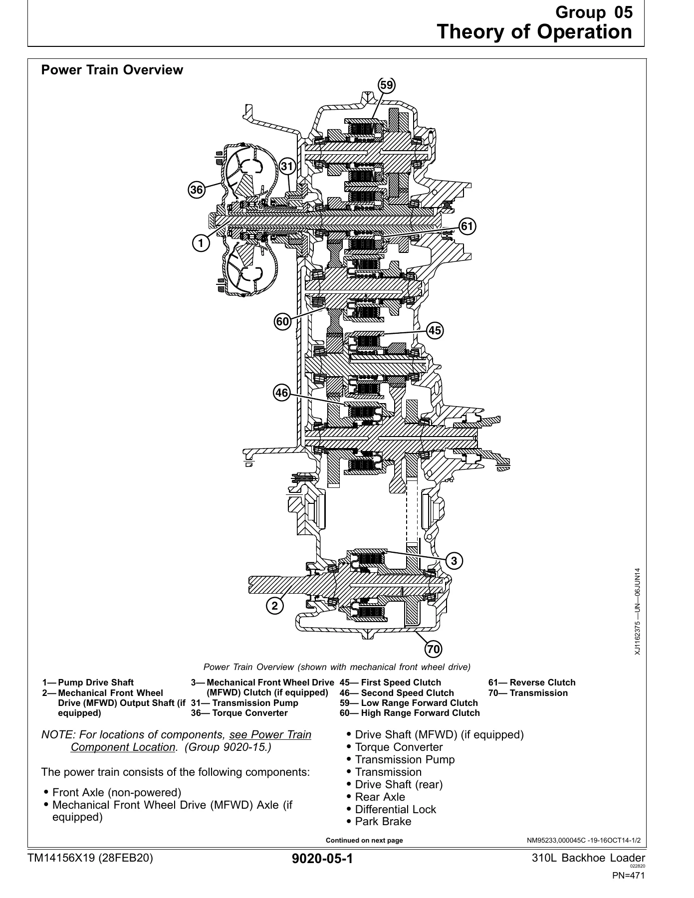
- Group 05 — Theory of Operation (power train overview, transmission pump, torque converter, transmission filter, clutch modulation, clutch pack, transmission gear flow, differential, differential lock, MFWD and MFWD differential, park brake, service brake, power boost brake valve, thermal bypass valve).
- Group 10 — System Diagrams (power train component location, power train schematic—first forward, power train schematic—neutral).
- Group 15 — Diagnostic Information (transmission malfunctions, slippage, lack of power, overheating, noise, MFWD, differential lock, axle oil, brakes).
- Group 20 — Adjustments (mechanical park brake release—towing, service brake pedal, brake bleed, tracking angle, toe-in, steering angle).
- Group 25 — Tests (oil warm-up, oil sampling, overall test connections, torque converter stall speed, torque converter inlet pressure, power boost brake valve leakage, park brake release pressure, transmission system pressure, service brake boost pressure, clutch pressure, differential lock pressure, MFWD pressure, cooler in/out pressure, solenoid circuit leakage, transmission pump flow).
- Section 9025 — Hydraulic System
- Group 05 — Theory of Operation (system operation, pump, filter, steering valve, ride control, backhoe control valve, pilot control valve, pilot enable and pattern select valve, loader and stabilizer control valve, system and circuit relief valves).
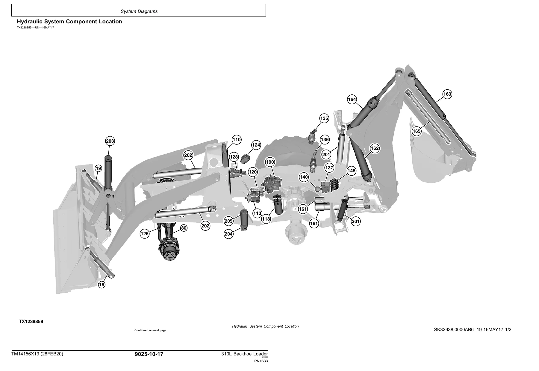
- Group 10 — System Diagrams (schematic symbols, hydraulic system schematic, component location, main/backhoe/pilot/loader/brake/steering/ride control line identification).
- Group 15 — Diagnostic Information (steering complaints, loader and backhoe power complaints, drift, valve sticking, oil overheating, foaming oil, pump leaks and noise).
- Group 20 — Adjustments (backhoe control lever linkage, auxiliary selective flow control, pilot control pressure, PEPS accumulator discharge, loader self-leveling and return-to-dig switch, loader and stabilizer lever, ride control accumulator charge/check/discharge).
- Group 25 — Tests (JT02156A analyzer installation, oil warm-up, oil sampling, circuit pressure release, deaeration, pump flow, pilot control pressure, pilot control accumulator charge, cooler restriction, circuit relief valve—remote pump, steering system leakage, steering cylinder leakage, function drift, hydraulic cylinder leakage, loader and stabilizer control valve lockout leakage, backhoe/stabilizer/steering system pressure, loader system pressure).
- Section 9031 — Heating and Air Conditioning
- Group 05 — Theory of Operation (air conditioning system cycle of operation).
- Group 10 — System Diagrams (component location).
- Group 15 — Diagnostic Information (system does not operate, does not cool, runs constantly, heating complaints, window fogging).
- Group 25 — Tests (R134a cautions and handling, oil charge capacity, refrigerant charge capacity, operational checks, visual inspection, compressor clutch test, leak test, hoses and tubing inspection, high/low pressure switch test, freeze control switch test, system test, operating pressure diagnostic chart).
What this manual gives a working technician is the diagnostic layer on top of the repair layer. Instead of guessing, the 310L Backhoe Loader Operation & Test Technical Manual TM14156X19 supplies the DTC lookup and diagnostic routines, the operational checkout that verifies the machine before testing, the theory of operation that explains how each system is supposed to behave, the schematics and component locations needed to trace a fault, and the pressure, flow, resistance, temperature and torque values needed to confirm a repair. Sections are cross-referenced — a DTC entry will point you to the specific diagnostic group, and a diagnostic group will point you to the specific test port, wiring diagram, or adjustment procedure.
Coverage by System
The Engine section covers the 4045HBZ01, 4045TBZ01 and 4045HBZ02 engine variants in the context of the 310L machine — cooling package configuration, cold start aid (cold start advance on the mechanical engines and glow plug system on the 4045HBZ02), slow and fast idle adjustment, hand throttle linkage, and diagnostic checks for coolant temperature, oil pressure, air filter restriction, engine speed, thermostat opening, and intake manifold pressure. Cross-references lead into the component technical manuals (CTM104, CTM207, CTM320) for engine-internal detail.
The Electrical System section is the largest part of the manual. It documents the CAN bus (machine CAN, CAN termination resistors, JDLink gateway), engine control circuits for the 4045HBZ02 with its sensors, injectors, EGR and variable geometry turbo actuators, the engagement and monitor unit (EMU) with all of its inputs and outputs, the start and charge circuit, hydraulic system electrical circuits (pilot enable, pattern select, ride control, selective flow), transmission control circuits (FNR, gear select, clutch disconnect, MFWD, differential lock, backup alarm, park brake), and JDLink. Every harness has a component location drawing and a wiring diagram with circuit data tables.
The Power Train section covers the single-stage dual-phase torque converter, the transmission pump, the four-forward/two-reverse power shift transmission with its five clutch packs, the differential, the differential lock, mechanical front wheel drive (MFWD) and its self-applied limited slip differential, the park brake and the power boost service brake valve. Tests include stall speed, converter inlet pressure, system pressure, clutch pressures, cooler differential, and solenoid circuit leakage.
The Hydraulic System section covers the open-center hydraulic system, the fixed displacement single gear pump, the priority valve, the backhoe control valve with its inlet, swing, boom, bucket, crowd, auxiliary and extendable dipperstick sections, the pilot control system with pilot enable and pattern select (PEPS) manifold, the loader and stabilizer control valve, ride control, and the steering and brake circuit. Tests cover flow, system and circuit pressures, cylinder and valve leakage, drift, and pilot pressure and accumulator charge.
The Heating and Air Conditioning section covers the R134a system cycle, the compressor, condenser, receiver-dryer, expansion valve, evaporator, freeze control switch and high/low pressure switch, along with capacities, operational checks, leak testing and a full operating pressure diagnostic chart.
Who This Manual Is For
This 310L Backhoe Loader Operation & Test Technical Manual TM14156X19 is written for experienced technicians. It assumes access to the standard shop tooling plus the Deere-specific diagnostic equipment the procedures call out — Service ADVISOR, the JDG10273 Diagnostic Test Box, the JT02156A Digital Pressure and Temperature Analyzer, JT07148 Flowmeter, JT02161 and JT02162 transducers, flex probe kits and the various quick couplers and tee fittings listed per test. The diagnostic trouble code sections cover the complete DTC list for the ECU, EMU, TCU and VCU, each entry with alarm level, machine response, circuit information, component location references, diagnostic test box information, possible causes and cross-references to the diagnostic routines.
Because the manual covers three engine variants and multiple options (cab vs. canopy, manual vs. pilot controls, MFWD, ride control, selective flow, extendable dipperstick, JDLink), some menu tables, schematics and procedures contain items that will not apply to every machine. The manual identifies which items are option-dependent throughout.
Why Buy the Operation & Test Technical Manual TM14156X19
Diagnosing modern equipment without the correct manual costs time and parts. A 310L that throws a converter oil temperature warning, refuses to release the park brake, loses MFWD, chatters in the hydraulics, or will not hold a clutch pressure is expensive to troubleshoot by substitution. This manual replaces that with the actual test procedure, the specification value the reading must fall within, and the schematic or component location needed to isolate the fault correctly the first time.
Every procedure is written for the 310L specifically, not a generic backhoe. Torque converter stall speed is given for each of the three engine models. System pressure, cooler differential, pilot accumulator charge, brake boost pressure, clutch pressures and function drift all have their own target values. The wiring diagrams and hydraulic schematics are drawn for this machine’s harness set — cab harness (W14), canopy harness (W16), engine harness (W10), transmission harness (W13), fuel injector harness (W57), roof harness (W17), and the rest — with each harness given a component location drawing as well as a wiring diagram so a connector can be found on the machine, not just on paper.
Delivery
The John Deere 310L Backhoe Loader Operation & Test Technical Manual TM14156X19 is delivered as an instant PDF download after checkout. No waiting for a courier, no damaged binder, no missing pages. Read it on a laptop in the shop, on a tablet at the machine, or print the section you need and take it with you. Whether you are chasing a diagnostic trouble code on a 4045HBZ02-powered 310L, setting up the pilot enable and pattern select manifold, or measuring transmission cooler pressure differential, the full manual is on hand from the moment you download it.
Reviews
There are no reviews yet.