

John Deere 310G Backhoe Loader Repair Manual TM1886 – Complete PDF Service Guide
Original price was: $47.95.$31.95Current price is: $31.95.
The complete John Deere 310G Backhoe Loader Repair Manual (TM1886), covering every major system from axles and transmission to hydraulics, electrical, loader and backhoe. 804 pages of step-by-step procedures, specifications, and diagrams in a single downloadable PDF.
Description
John Deere 310G Backhoe Loader Repair Manual — TM1886
This is the complete John Deere 310G Backhoe Loader Repair Manual, publication TM1886, dated 03FEB05. It is the same technical manual used by service technicians to diagnose, repair, and maintain the 310G backhoe loader, and it is now available as a single downloadable PDF. The manual covers the machine from the wheels up, with dedicated sections for the axles, transmission, engine, hydraulic system, loader, backhoe, electrical system, and operator’s station. Every procedure is supported by specifications, torque values, and illustrations where the original publication includes them.
File Details
- Manual Type: Repair / Technical Manual
- Brand: John Deere
- Model: 310G Backhoe Loader
- Language: English
- Page Count: 804 pages
- File Format: PDF
- Document Number: TM1886
- Edition / Date: 03FEB05 (English)
Chapters Covered
The 310G repair manual is divided into numbered sections, each with its own contents page, service equipment list, specifications, and step-by-step procedures. The full chapter list is shown below.
- Section 00 — General Information
- Section 01 — Wheels
- Section 02 — Axles and Suspension Systems
- Section 03 — Transmission
- Section 04 — Engine
- Section 05 — Engine Auxiliary Systems
- Section 06 — Torque Converter
- Section 09 — Steering System
- Section 10 — Service Brakes
- Section 16 — Electrical Systems
- Section 17 — Frames, Chassis or Supporting Structure
- Section 18 — Operator’s Station
- Section 19 — Sheet Metal and Styling
- Section 20 — Safety, Convenience and Miscellaneous
- Section 21 — Main Hydraulic System
- Section 31 — Loader
- Section 33 — Backhoe
- Section 99 — Dealer Fabricated Tool
Section 00 — General Information
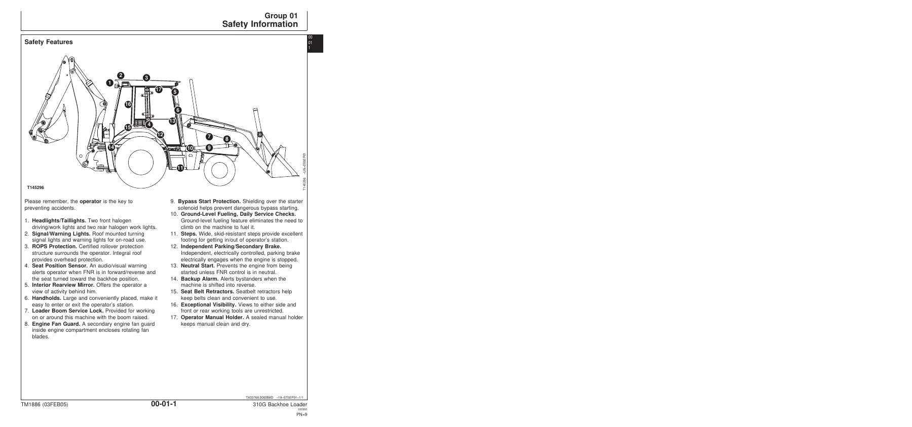
Safety information, warning conventions, and general service guidance that applies across the machine. This section includes the safety alert system, personal protective equipment requirements, high-pressure fluid warnings, and safe parking and service procedures.
Sections 01 and 02 — Wheels, Axles and Suspension Systems
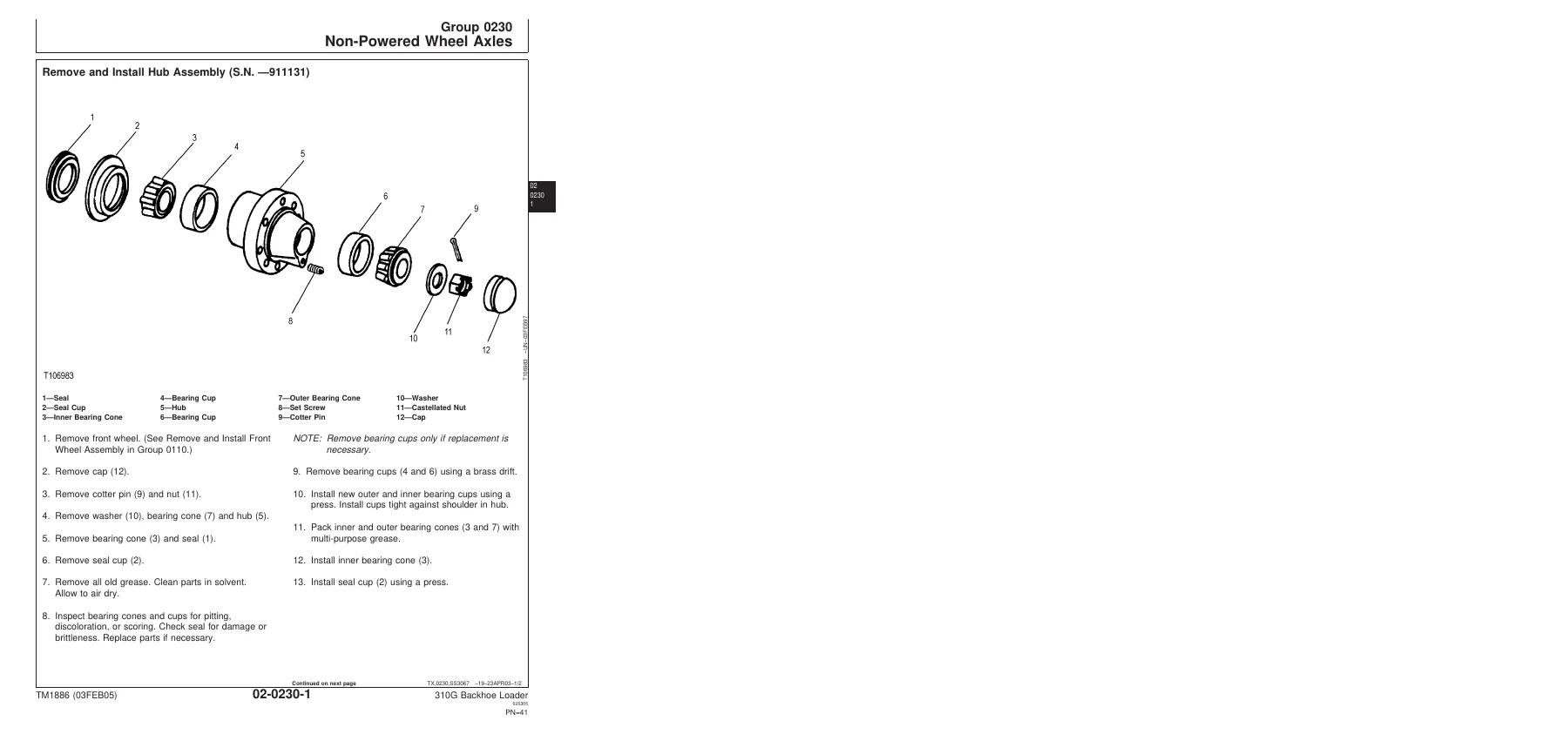
Wheel removal and installation for both powered and non-powered wheels, including tire handling and inflation safety. The axle section covers input drive shafts and U-joints, non-powered front axle hub and spindle assemblies, the mechanical front wheel drive (MFWD) axle, and the rear axle shaft, bearings, reduction gears, and park brake. Procedures include rear axle disassembly, gear tooth contact pattern checking, and the complete park brake shimming and assembly process.
Section 03 — Transmission
Transmission removal and installation, control linkage, input drive shafts and U-joints, gears, shafts, bearings, power shift clutch packs, and the hydraulic control system. This is one of the deepest sections in the manual, covering the disassembly and assembly of the forward and reverse clutch packs, the drive shaft, the rear output shaft, the intermediate shaft, the MFWD output shaft, and the idler shaft.
Sections 04 and 05 — Engine and Engine Auxiliary Systems
Engine removal and installation for the POWERTECH 4.5 L (4045) and 6.8 L (6068) diesel engines. Auxiliary systems include cold weather starting aids, the cooling system (fan, belt, and radiator), speed controls, the intake system, the exhaust system, and the external fuel supply system.
Section 06 — Torque Converter
Torque converter removal, installation, disassembly, and assembly. Note that this converter is a sealed unit with no internal service parts — replacement is the recommended service action if the unit fails.
Sections 09 and 10 — Steering and Service Brakes
The steering section covers the steering column, steering valve, non-powered axle steering cylinder, MFWD steering cylinder, and the steering bushings. The service brake section covers brake disk and pressure plate removal and installation, brake valve removal and disassembly, brake pedal adjustment, and brake bleeding procedures.
Section 16 — Electrical Systems
Batteries, battery testing and charging, the alternator, wiring harness routing, connector repair, instrumentation, the starter motor, and the starter relay. The electrical section is a practical guide for diagnosing charging, starting, and instrument faults on the machine.
Section 17 — Frames, Chassis and Supporting Structure
Frame installation, main frame bushings, counterweight removal and installation, and welding repair of major structures. The section includes guidance on RIVNUT fastener installation and safe welding practices to avoid electrical damage to the machine.
Sections 18, 19, and 20 — Operator’s Station, Sheet Metal, and Accessories
The operator’s station section covers cab and ROPS removal and installation, cab doors and windows, wipers, the headliner, cab roof, seat and seat belt, seat suspension, and the air seat suspension (if equipped). Sheet metal and styling covers the hood, engine enclosure, battery box, grille, fenders, and cab skirt. Safety, convenience, and miscellaneous covers the radio, speakers, antenna, horn, and back-up alarm.
Section 21 — Main Hydraulic System
The hydraulic pump, hydraulic filter assembly, reservoir, hydraulic and transmission oil coolers, and the hydraulic oil cooler used with air conditioning. The section includes pump disassembly, seal replacement, and torque specifications for the system’s key components.
Section 31 — Loader
Loader removal and installation, loader bucket and cutting edge service, control linkage adjustment, the bucket self-leveling linkage and return-to-dig switch (including the serial-number split between the early and late adjustment procedures), the loader control valve, circuit relief valves, the ride control system (valve, solenoid, and accumulator), the loader bucket cylinder, the loader boom cylinders, and the multi-purpose bucket. The ride control accumulator charging procedures are covered in detail.
Section 33 — Backhoe
Backhoe bucket, bucket links, and bucket tooth shanks and tips; the backhoe boom swing lock control lever and linkage; the backhoe boom lock arms and locking pin; the two-lever and three-lever backhoe valve linkages; the pilot control valve and pilot control tower (optional); the fifth and sixth function pedals; the stabilizer valve linkage; the backhoe frames (dipperstick, boom, and swing frame); the extendible dipperstick extension; the backhoe control valve sections; the circuit relief valves; the stabilizer valve; the backhoe cylinders (bucket, crowd, boom, swing, and stabilizer); and the extendible dipperstick cylinder.
Section 99 — Dealer Fabricated Tool
Drawings and instructions for building the special tools referenced throughout the manual, including the axle mounting bracket, axle rolling torque bar, transmission support bracket, MFWD snap ring tool, compressor holding fixture, and cab/ROPS lift bracket.
Why This Manual Matters for 310G Owners and Technicians
The John Deere 310G is a workhorse backhoe loader, and keeping it running correctly depends on having the right procedures and specifications. This manual provides both. Every major system — from the engine and transmission to the hydraulic and electrical systems — is covered with the same step-by-step structure the dealer service department uses. You get the torque values for the rear axle mounting cap screws, the rolling drag torque for the inner axle bearing, the shim pack dimensions for the park brake, the service brake inspection gap, and hundreds of other specifications that are easy to get wrong without the book.
For independent shops and owner-operators, the value is in not having to guess. When you pull the transmission, you know which cap screws to replace and what torque to use. When you rebuild the park brake, you have the shim measurement procedure in front of you. When the loader self-leveling linkage is not working right, you have the adjustment procedure and the correct gap to measure. That saves time, avoids rework, and keeps the machine working the way it was designed to.
The manual is also useful for diagnosing problems. If the machine is not charging, the electrical section walks through the alternator wiring. If the backhoe is drifting, the circuit relief valve information and the anti-drift check plug procedure are there. If the brakes feel soft, the brake valve and bleeding procedures are included.
What You Get with This Download
This is a complete PDF download of the John Deere 310G Backhoe Loader Repair Manual, TM1886, dated 03FEB05. It is the full manual — not a sample, not an excerpt, not a collection of unrelated pages. Once your payment is processed, you can download the file and open it on any device that supports PDF: a laptop, desktop, tablet, or phone. You can print the pages you need for the shop, or keep the whole manual on a tablet for quick reference in the field. There is no shipping, no waiting for a physical book, and no risk of losing a paper copy.
The PDF is organized exactly as the original manual is organized, with each section beginning with its own contents page, service equipment list, and specifications. The page numbers in the file follow the manual’s own pagination, so when a procedure refers you to a specific group or section, the cross-reference works.
Who This Manual Is For
This manual is written for the experienced technician, but it is also useful for the owner-operator who wants to understand the machine and do their own maintenance and repairs. John Deere’s foreword states that the manual is written for an experienced technician and that technical manuals are concise guides for specific machines — meaning the procedures assume a base level of mechanical skill and familiarity with tools. If you are new to heavy equipment repair, the manual will still be useful, but you will want to combine it with hands-on training and supervision.
The manual covers the POWERTECH 4.5 L (4045) and 6.8 L (6068) diesel engines used in the 310G. It does not cover the engine internally in the same depth as the machine systems — the foreword points to separate Component Technical Manuals (CTM104, CTM207, CTM331) for base engine and fuel system details. If you need to go inside the engine itself, those CTMs are the next step. For everything around the engine — cooling, fuel supply, exhaust, intake, starting aids, and removal and installation — this manual is the reference.
Note also that some procedures in this manual are split by serial number. The park brake, for example, has different disassembly and assembly procedures for early and later serial ranges. The loader self-leveling linkage has different adjustment procedures for early and later serial ranges. Check your machine’s serial number against the procedure heading before you start, so you are using the correct steps.
Get the Complete John Deere 310G Repair Manual Today
IMAGES PREVIEW
If you own, service, or maintain a John Deere 310G Backhoe Loader, this manual belongs in your shop. It is the same technical content that would sit on a dealer’s service shelf, packaged as a single PDF you can download immediately. Use it to plan a repair, check a specification, order the right parts, or train a new technician. The download link is delivered as soon as your payment is complete, and the file is yours to keep and use on your own devices.
Reviews
There are no reviews yet.