
John Deere 7200R, 7215R, 7230R, 7260R, 7280R Repair Technical Manual TM110119 PDF
Original price was: $80.95.$59.95Current price is: $59.95.
Complete John Deere 7200R, 7215R, 7230R, 7260R and 7280R Repair Technical Manual TM110119, covering engines, transmissions, MFWD axles, hydraulics, electrical, brakes and operator station for serial numbers 000101-080000.
Description
John Deere 7200R, 7215R, 7230R, 7260R, 7280R Repair Technical Manual TM110119
This John Deere 7200R, 7215R, 7230R, 7260R and 7280R Repair Technical Manual, document TM110119, is a 2680-page PDF written for the technician who needs to remove, disassemble, inspect, repair, assemble and reinstall major tractor systems. It covers the 7200R, 7215R, 7230R, 7260R and 7280R tractors within serial number range 000101-080000. The manual is dated May 2013 and includes engine, fuel and cooling, electrical, transmission, drive systems, MFWD axles, steering and brakes, hydraulics, operator station and dealer tool information. Whether you are diagnosing a transmission fault, rebuilding a final drive, servicing the cooling package or tracing an electrical circuit, this John Deere 7200R-7280R repair technical manual gives you the procedures and values in one organized PDF.
File Details
- Manual type: Repair Technical Manual
- Brand: John Deere
- Models: 7200R, 7215R, 7230R, 7260R, 7280R
- Document number: TM110119
- Date: May 2013
- Serial number range: 000101-080000
- Language: English
- Page count: 2680
- File format: PDF
Chapters Covered
- Section 10 – GENERAL INFORMATION
- Section 20 – ENGINE
- Section 30 – FUEL AND COOLING SYSTEMS
- Section 40 – ELECTRICAL
- Section 50 – AUTOQUAD/COMMANDQUAD TRANSMISSION
- Section 51 – AUTOPOWR/IVT TRANSMISSION
- Section 56 – DRIVE SYSTEMS
- Section 57 – 1100 SERIES MFWD AXLE
- Section 58 – 1300 SERIES MFWD AXLE
- Section 59 – SUSPENDED MFWD AXLE
- Section 60 – STEERING AND BRAKES
- Section 70 – HYDRAULICS
- Section 80 – MISCELLANEOUS
- Section 90 – OPERATOR STATION
- Section 99 – DEALER TOOLS
General Information and Safety
Section 10 opens with safety messages, signal words, protective clothing, high-pressure fluid warnings, battery and acid handling, exhaust filter precautions and safe service practices. It also includes general repair information such as sealants and adhesives, metric and unified inch bolt torque values, face seal fitting installation, four-bolt flange fitting torque, external hexagon port plug torque, hydraulic contamination prevention, electrical component handling, zinc-flake fastener identification, torque wrench adapter use, Snap to Connect STC fitting service and a glossary of terms. This is where the technician finds the baseline torque charts and cleanliness rules that apply before any teardown begins.
Engine Removal, Installation and Repair
Section 20 covers component removal and installation for the 6.8L and 9.0L engines, including hood and side shield removal, battery disconnect, air conditioning discharge, coolant draining, radiator hose and deaeration tank removal, air-to-air cooler pipes, fuel cooler lines, harness covers, heat shields, exhaust pipes, auxiliary drive shaft, hood support, exhaust filter and bracket, engine lifting brackets, drive shaft yoke, oil pan and engine mount details. Engine repair includes rocker arm cover removal and installation for both 6.8L and 9.0L engines, valve clearance checks, baffle installation, OCV filter housing, oil fill cap seal and flywheel dampener replacement. Torque-turn sequences and cap screw specifications are given for the major engine fasteners.
Fuel and Cooling Systems
Section 30 covers the diesel fuel system, air intake system, auxiliary drive system, radiator and coolers, and exhaust system. Procedures include left-hand and right-hand fuel tank removal and installation, fuel filter and fuel pump service, fuel system bleeding, air intake pipe connections, intake housing, aspirator hose, charge air cooler pipes for 6.8L and 9.0L engines, fan belt, water pump drive belt, belt tensioner inspection, electronic fan drive, cooling system draining, flushing and refilling, radiator and deaeration tank testing, radiator cap testing, charge air cooler, fan shroud, radiator, fuel coolers, air conditioning condenser, hydraulic oil cooler and exhaust system service. The section includes clamp torque values, hose routing and component weights where relevant.
Electrical Systems
Section 40 begins with connectors and includes repair procedures for AMP, AMPSEAL 16, CAN controlled SCV, CINCH Wedgebox, CINCH Flexbox, CPC, MATE-N-LOC, METRIMATE, DEUTSCH, ITT, METRI-PACK, Molex, SUMITOMO, Tyco fuel injector, Weather Pack and YAZAKI connectors. Wiring harness routings are listed for convenience outlets, roof control unit, cab control unit, alternator, battery cables, power module relay, hood light, power mirror, extremity light, front console, steering column, roof HVAC, auxiliary audio, microphone, fender, key switch, implement lighting, radar, 2WD and MFWD chassis, TLS Plus chassis, ACS chassis, rear chassis, transmission, front chassis, engine coolant sensors, cab harnesses, armrest control, mid-stack SCV, draft sensor, wheel angle sensor, front brake valve, front PTO, backup hydraulic pump, secondary brake valve, front ISO implement connector, JDLink, roof lighting, ISO 11786 cornerpost, air trailer brake, ActiveSeat, standard seat and heated seat harnesses. Charging circuit, starting circuit, relays, fuses, solenoids, switches and monitoring system components are also covered.
AutoQuad and CommandQuad Transmissions
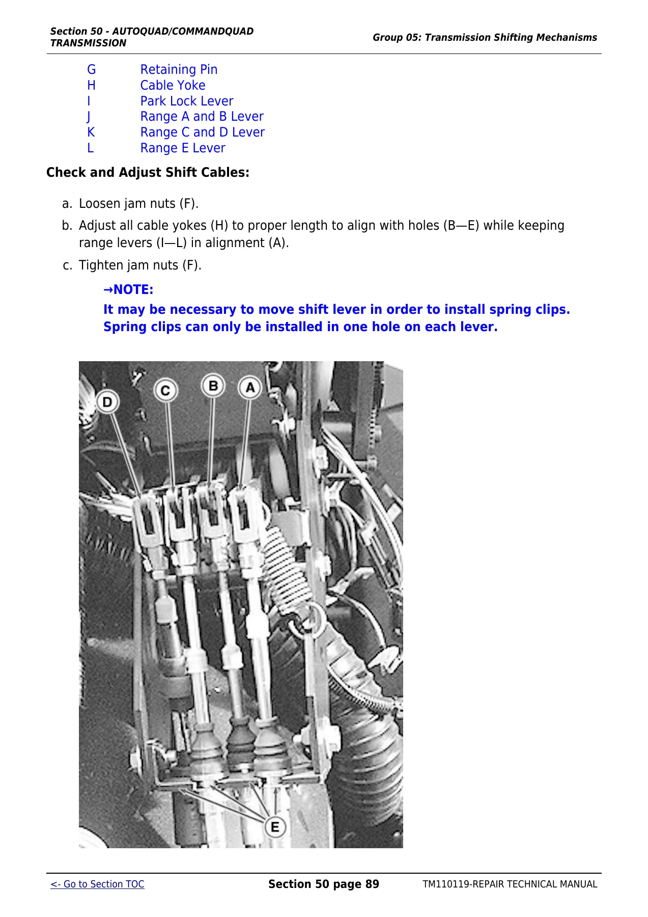
Section 50 covers component removal and installation for the AutoQuad/CommandQuad transmission family. Procedures include transmission removal and installation, PowrQuad removal and installation, range box removal and installation, MFWD clutch removal and installation, shift lever reconditioning, range shift linkage repair, shift cable removal and adjustment, PowrQuad-Plus module service, transmission boost valve, cooler bypass valve, front transmission cover valves, shift valve housing, transmission front cover, transmission oil pump, gear-shift planetary drive, B1, B2 and B3 brakes, C4 clutch, reverse brake, forward clutch with planetary drive and output shaft replacement. The range box sections cover PowrQuad, AutoQuad and CommandQuad disassembly, MFWD clutch repair, park pawl or park brake repair, input shaft, output shaft, shift control housing, rear cover, bearing cups, shift forks, sensors and valve assemblies.
AutoPowr and IVT Transmissions
Section 51 covers the AutoPowr/IVT transmission. It includes transmission removal and installation, general repair procedures, hydrostatic module replacement, separation of transmission housings, repair stand installation, disassembly of the IVT transmission, front valve housing, rear valve housing, hydrostatic gear train, synchronizer, mode 2 and mode 3 clutch assemblies, MFWD clutch, park brake, reverse idler, mode-1 clutch, SU idler, input planetary, mode 2 clutch, mode 2 shaft, differential drive shaft and accumulator. Assembly procedures cover hydrostatic module installation, front valve housing, bearing cups in the rear housing, output shaft assembly, mode-1 clutch assembly, mode 3 clutch assembly, park brake, reverse shaft assemblies, synchronizer assembly, MFWD clutch assembly, bearing support and bearing adjustment, transmission housing assembly, rear valve housing and sensors.
Drive Systems and Axles
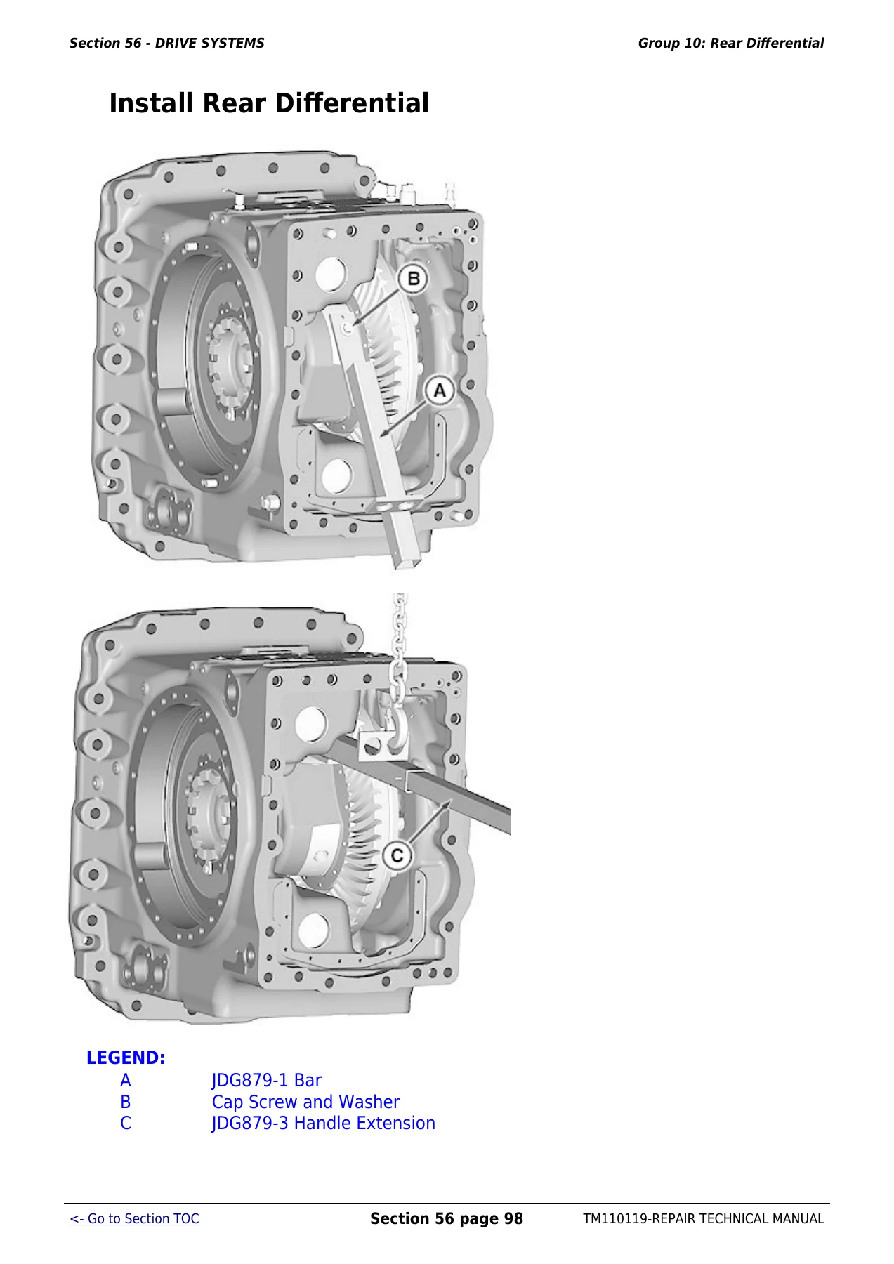
Section 56 covers drive systems including front PTO assembly removal and installation, differential case removal and installation, final drive removal and installation, rear differential repair, final drive repair, rear PTO repair and front PTO repair. Section 57 covers the 1100 Series MFWD axle with non-suspended axle removal and installation, final drives, axle housing, differential, planetary carrier and wheel hub, knuckle spindle assembly, kingpin bearings and shims. Section 58 covers the 1300 Series MFWD axle with similar removal, final drive, axle housing and differential procedures. Section 59 covers the suspended MFWD axle, including final drives with and without brakes, knuckle spindle assembly, axle housing, limited slip and locking differentials, differential drive shaft, suspension components, hydraulic control valve block, position sensor, cylinder seals and accumulator charging.
Steering and Brakes
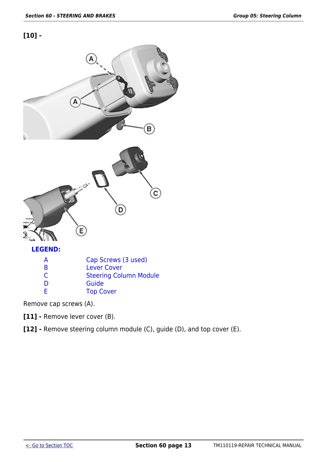
Section 60 covers steering column repair, including ActiveCommand Steering, steering control assembly, steering valve, AutoTrac valve, ActiveCommand Steering valve, return circuit relief valve, priority valve housing, backup manifold, backup pump and steering system bleeding. Steering cylinders for MFWD and two-wheel drive are included with repair procedures. Service brakes include brake rods, brake valve manual and powered backup, front brake valve, secondary brake valve, brake control manifold, lube manifold, park brake release manifold, manual park brake release for IVT and CommandQuad, MFWD brake bleeding, brake bleeding and brake checks. Hydraulic trailer brake and air trailer brake systems are covered, including air compressor, pre-brake valve, park valve, trailer brake valve and air pressure control valve.
Hydraulics
Section 70 covers hydraulic component removal and installation, general repair procedures, draining, filling and bleeding the hydraulic system, integrated hydraulic pump, compensator valve, transmission pump, scavenge and lube pump, mid-stack valve, hitch-SCV valve stack, rear hitch frame, front 3-point hitch, hitch valve, selective control valves and couplers, pressure compensator, pressure compensating check valve, spool centering spring assembly, surge relief valve, shuttle valve, coupler housing and coupler repair. Rear hitch lift cylinders, rockshaft bushings and draft sensing are also included, along with front hitch lift cylinders and repair procedures.
Miscellaneous, Operator Station and Dealer Tools
Section 80 covers hood positioning, hood removal and installation, grille and headlight assembly, light adjustment, aiming headlights, hood side panels, hood screens and hood latch. Section 90 covers the operator station, including cab removal and installation, cab repair, inner roof removal and installation, HVAC module, heater control valve, mode control cable, air conditioning system discharge, flushing, purging, evacuation, charging, refrigerant oil, compressor, receiver-dryer, expansion valve and condenser. Seat sections cover air suspension seat, ComfortCommand seat, ActiveSeat, armrest, cab door and windshield, cab suspension depressurization, leveling control valve, sensor rod, position sensor, accumulator, hydraulic cylinders, Panhard rod and bleeding the suspended cab system. Section 99 lists dealer fabricated tools and essential recommended tools used throughout the manual.
What This John Deere 7200R-7280R Repair Manual Lets You Do
The John Deere 7200R, 7215R, 7230R, 7260R and 7280R Repair Technical Manual TM110119 is built around real service work. It gives you the removal and installation order, the component repair steps, the torque values, the wear limits, the spring free lengths, the end play specifications, the bearing adjustment procedures, the diagnostic pressure checks and the assembly sequences needed to work on these tractors. You can use it to service a 6.8L or 9.0L engine, repair an AutoQuad, CommandQuad, PowrQuad, AutoPowr or IVT transmission, rebuild a 1100 Series, 1300 Series or suspended MFWD axle, repair the rear differential or final drive, overhaul the rear or front PTO, repair the steering system, bleed and check the brakes, service the hitch and selective control valves, trace electrical harnesses, repair connectors, service the HVAC system, repair the cab suspension or work on the operator station. Because the manual covers serial number range 000101-080000 and names the specific models, you are not left guessing whether a procedure applies to your tractor.
Why Correct Procedures and Specifications Matter
On a tractor of this size, a guessed torque, an overlooked shim, an incorrect end play setting or a missed bleeding step can turn a repair into a repeat failure. The John Deere 7200R-7280R repair manual keeps the critical numbers in front of you: engine lifting bracket cap screw torque, torque-turn sequences, fuel and cooling system clamp torques, transmission clutch and brake specifications, axle bearing preload and backlash, differential drive shaft end play, hydraulic valve spring dimensions, brake bleed pressures and cab suspension accumulator charge pressures. It also shows you the tools required for each job, including JDG lifting eyes, spline sockets, seal installers, spring compressors, bearing installers, differential housing tool sets and diagnostic adapters. When you follow the manual, you reduce the risk of damaged seals, distorted housings, incorrect bearing preload, contaminated hydraulic systems and electrical faults caused by incorrect connector repair.
IMAGES PREVIEW
Instant PDF Delivery for the John Deere 7200R-7280R Repair Technical Manual
This John Deere 7200R, 7215R, 7230R, 7260R and 7280R Repair Technical Manual TM110119 is delivered as an instant PDF download after payment. There is no shipping, no waiting for a paper book and no risk of a lost parcel. You can open it on a workshop computer, laptop, tablet or smartphone, and you can print the pages you need for the job. Keep the complete 2680-page manual on your device for quick search by system or section, or print the transmission, engine, axle, hydraulic or electrical pages and take them to the tractor. Whether you are a professional technician, a dealer service department or an owner who does serious repair work, this PDF gives you the complete John Deere 7200R-7280R repair technical manual in a convenient, portable format.
Reviews
There are no reviews yet.