Description
File Details
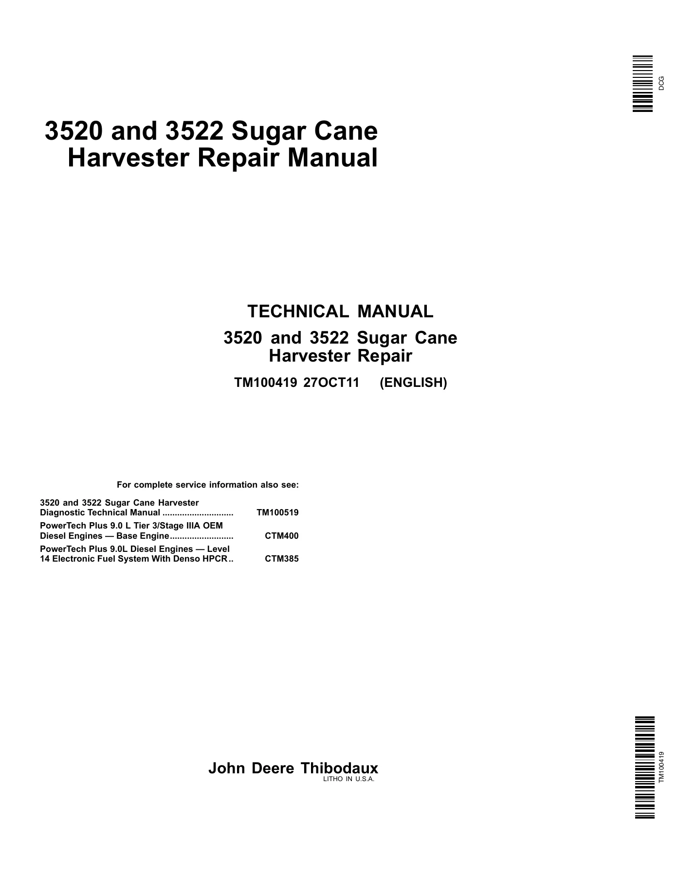
- Manual Type: Repair Technical Manual
- Document Number: TM100419
- Publication Date: 27 October 2011 (27OCT11)
- Models Covered: John Deere 3520 and 3522 Sugar Cane Harvesters
- Language: English
- Pages: 588
- File Format: PDF
- Publisher Note: John Deere Thibodaux, Litho in U.S.A.
What This Manual Covers
The John Deere 3520 3522 Sugar Cane Harvester Repair Technical Manual TM100419 is organized into fourteen major sections, each addressing a distinct machine system or assembly group. The table of contents runs deep — most sections are subdivided into multiple groups with their own tools lists, specifications, wear tolerances, and torque values before the repair procedures begin.
- Section 10 — General
- Group 05: Safety (operation safety, service safety, accumulator safety, fire prevention, hazardous areas)
- Group 10: Specifications — John Deere 6090 Engine PowerTech
- Group 15: General Capacities (harvester fluid capacities, tire inflation pressures)
- Group 20: Torque Specifications (component-specific torques, metric and unified inch bolt torque charts, fitting torque tables for SAE 37°/JIC, ORS, BSPP, four-bolt flange)
- Group 25: Fluid Recommendations (engine coolant, hydraulic fluid, diesel fuel, engine oil, gear oils, grease)
- Group 30: General Information (conversions, specialty tools, harvester specialty tool part numbers)
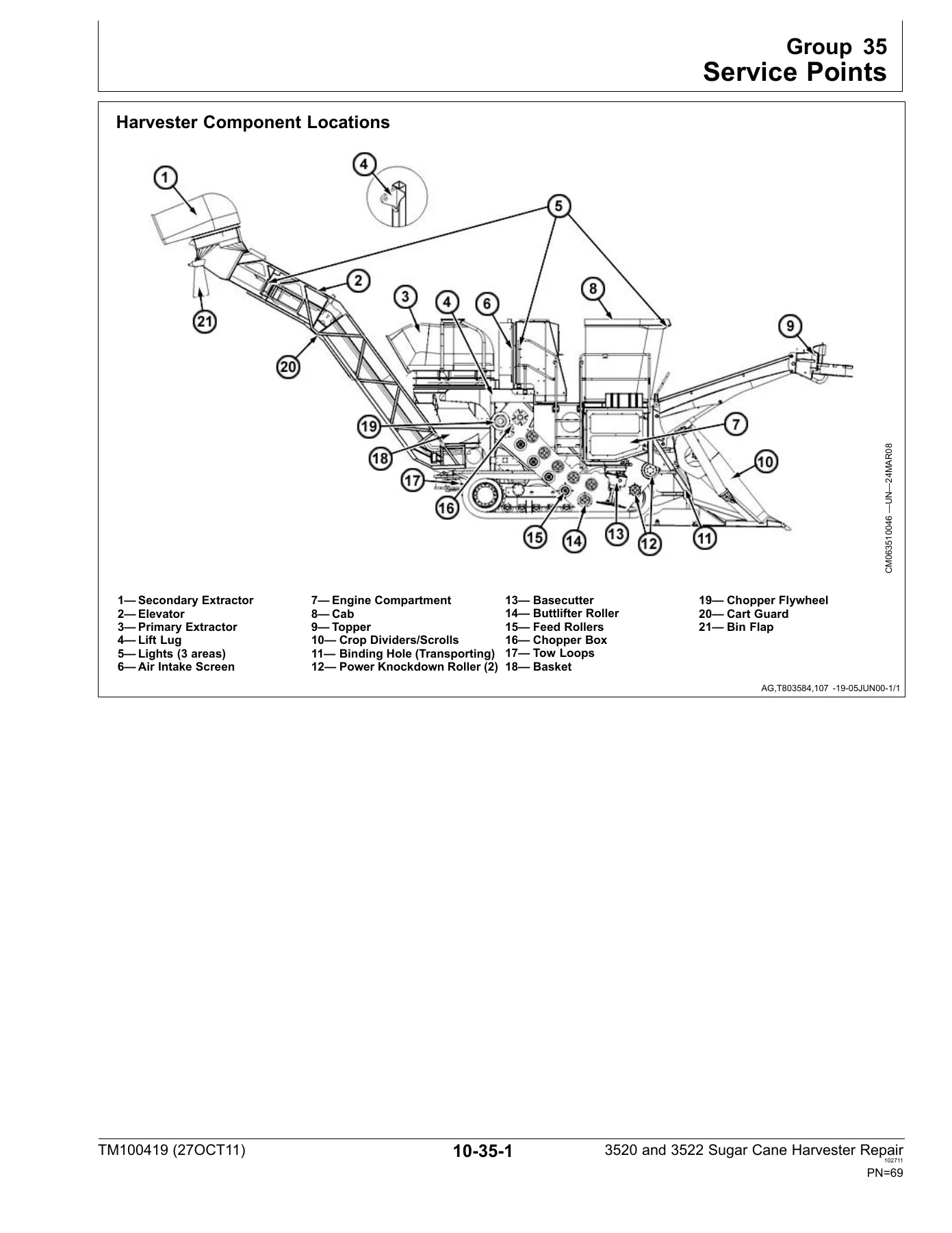
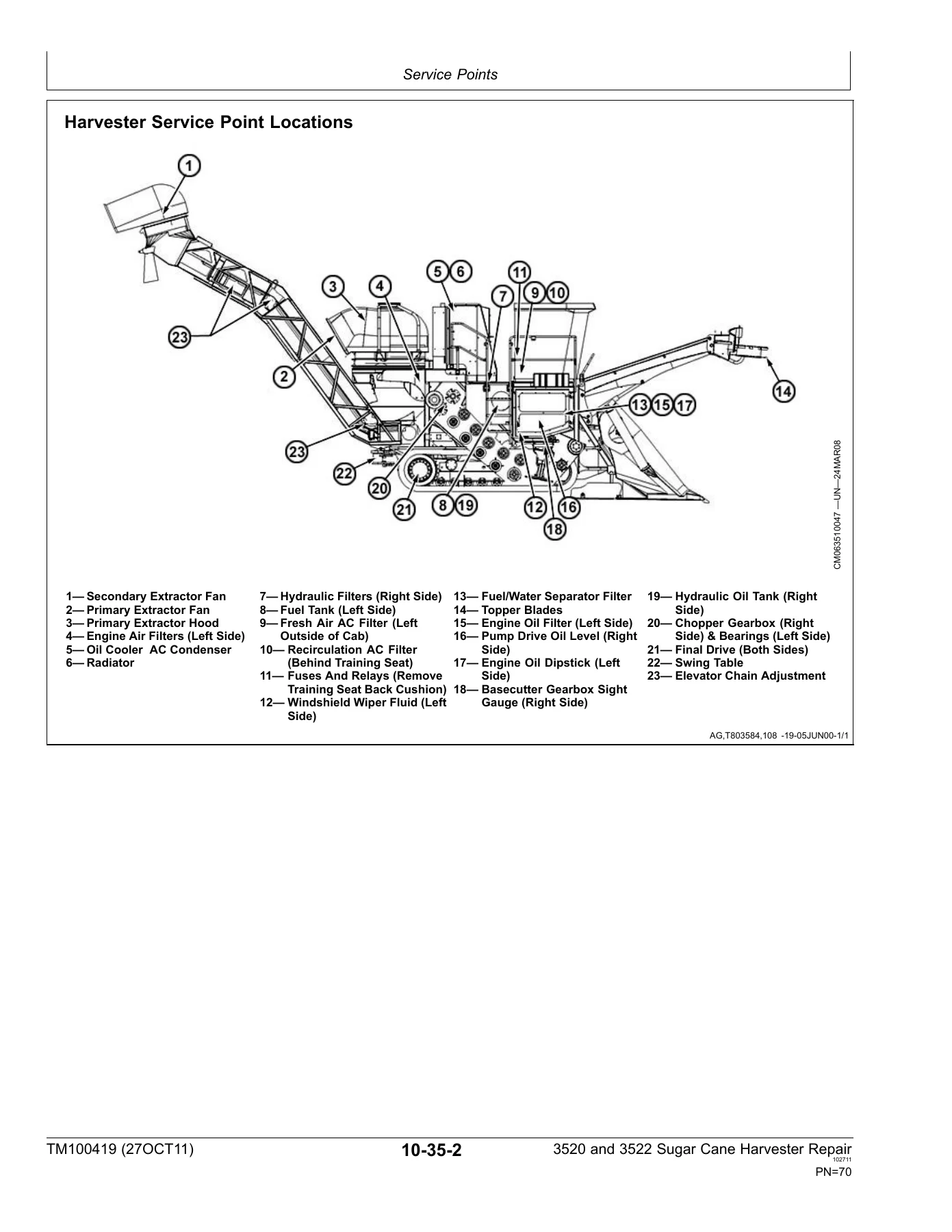
- Group 35: Service Points (component locations, service point locations, grease point locations)
- Section 20 — Engine
- Group 05: Pump Drive Gear Box
- Section 30 — Feed Roller System
- Group 05: Knockdown Roller
- Group 10: Buttlifter Roller (B1)
- Group 15: Bottom Feed Roller
- Group 20: Top Feed Roller
- Section 40 — Electrical
- Group 10: Electrical Harness and Connectors (Weather Pack, Metric-Pack, Deutsch connector service; terminal extraction and installation procedures)
- Section 50 — Hydrostatic System
- Group 05: Planetary Final Drive Bonfiglioli
- Group 10: Planetary Final Drive Iberica
- Group 15: Track
- Group 20: Wheel
- Section 60 — Steering System
- Group 05: Steering Column (Type A)
- Group 10: Steering Column (Type B)
- Group 15: Steering Wheel Position Input Assembly (Autotrac Ready Track Machines)
- Group 20: Relief Valve
- Section 70 — Main Hydraulic System
- Group 10A: Multiple Gear Pump
- Group 10B: Piston Pump
- Group 20A: Steering Cylinder
- Group 20B: Crop Divider Cylinder
- Group 20C: Crop Divider Tilt Cylinder
- Group 20D: Topper Cylinder
- Group 20E: Basecutter Cylinder
- Group 20F: Elevator Cylinders
- Group 20G: Height Indicator Cylinder
- Group 20H: Cab Tilt Cylinder
- Group 20I: Knockdown Tilt and Crop Divider Tilt Cylinder
- Group 30A: Fixed Displacement Motor
- Group 30B: Collector, Crop Divider, Feedroller and Elevator Motor
- Group 30C: Topper and Secondary Extractor Motor
- Group 30D: Basecutter and Primary Extractor Motors
- Group 30E: Secondary Extractor Hood Rotate Motor
- Group 30F: Cooling Package/Oil Cooler Motor
- Group 30G: Variable Displacement Ground Drive Motor (Wheel)
- Group 30H: Fixed Displacement Motor (Track)
- Group 30I: Chopper Motor
- Group 40A: Rear Feed Roller Valve
- Group 40B: Steering Priority Valve (Wheel)
- Group 40C: Steering Valve
- Section 80 — Topper System
- Group 05: Collector, Crop Divider, Feed Roller and Elevator Motor
- Section 90 — Operator’s Station
- Section 100 — Crop Divider System
- Section 110 — Basecutter System
- Group 05: Basecutter Gearbox
- Group 10: Basecutter Lift Cylinder Accumulators
- Section 120 — Chopper System
- Section 130 — Cleaning System
- Group 05: Primary Extractor
- Section 140 — Elevator System
- Group 05: Elevator Systems Installation
Complete PDF Bookmark Tree
Complete Bookmarks
The complete bookmarks in the “John Deere 3520 3522 Sugar Cane Harvester Repair Technical Manual TM100419” are as follows:
+Contentsp. 3
+Generalp. 6
+Safetyp. 7
Safety and Youp. 7
Operation Safetyp. 7
Safety instructionsp. 8
Service Safetyp. 9
Safety in Your Service Areap. 10
Safety when Cleaning or Storingp. 10
Safety Neversp. 11
Seat Safety Shut-offp. 11
Tilting the Cabp. 12
Recognize Safety Informationp. 12
Understand Signal Wordsp. 13
Follow Safety Instructionsp. 13
Protect Bystandersp. 14
Use Handles and Stepsp. 14
Avoid Exhaust Fumesp. 15
Wear Protective Clothingp. 15
Handle Fuel Safely — Avoid Firesp. 16
Safely Service Accumulatorp. 16
Accumulator Safetyp. 17
Safely Service Cooling Systemp. 17
Prepare for Emergenciesp. 18
Use Safety Lights and Devicesp. 18
Use Cylinder Safety Stopsp. 19
Safe Transport of Harvesterp. 19
Avoid High-Pressure Fluidsp. 20
Use Caution on Hillsidesp. 20
Stopping and Parkingp. 21
Service Tires Safelyp. 21
Tire Inflationp. 22
Avoid Electrical Power Linesp. 22
Keep Hands Away From Knivesp. 23
Avoid Contact With Moving Partsp. 23
Dispose of Waste Properlyp. 24
Fire Preventionp. 24
Safety Recommendationsp. 25
Avoid Serious Injuryp. 25
Hazardous Areap. 26
Stay Clear of Chopper Areap. 27
Rotating Chopper Drump. 28
Avoid Hazardous Areap. 29
Avoid Electrical Power Linesp. 30
Safe Service Practicep. 31
Prevent Firesp. 32
Training Seatp. 33
Avoid Personal Injury and Damage to the Machinep. 34
Keep Hands Awayp. 35
Keep Away From Rotating Knivesp. 36
Avoid Injuryp. 37
Preventing Machine Runawayp. 38
Exhaust System Warningp. 39
+Specificationsp. 41
Specifications — John Deere 6090 Engine PowerTechPowerTech is ap. 41
Preliminary Service Intervalsp. 41
Common Wear Partsp. 41
+General Capacitiesp. 43
Harvester Capacitiesp. 43
Tire Inflation Pressurep. 43
+Torque Specificationsp. 45
Torque Specificationsp. 45
Torque for Grade 2 NC Weld Studsp. 45
Metric Bolt and Screw Torque Valuesp. 46
Unified Inch Bolt and Screw Torque Valuesp. 47
Suggested Torque Values and Clamp Loads for Grades 2, 5, & 8 Bop. 48
Suggested Torque Values For Grades 5.6, 8.8, 10.9, 12.9 Zinc Plap. 48
Grade or Property Class Head Marking for SI Boltsp. 49
Conversion Factorsp. 49
Straight O-Ring Boss Fittingsp. 49
Angled O-Ring Boss Fittingsp. 49
SAE 37° (JIC)p. 50
Metricp. 50
BSPP (Port Connection Only)p. 50
ORSp. 51
Straight Thread O-Ring Bossp. 51
37° Flare Cone Fittingsp. 51
Hex Flats Recommended Rotationp. 52
Four Bolt Flange Fittingsp. 52
SAE Bolt Torque Chartp. 53
+Fluid Recommendationsp. 55
John Deere Engine Coolant Requirementsp. 55
John Deere Prediluted Antifreeze/Summer Coolantp. 55
Heavy Duty Diesel Engine Coolantp. 55
John Deere Antifreeze/Summer Coolant Concentratep. 56
John Deere Antifreeze/Summer Coolantp. 56
Hydraulic Fluid (World)p. 56
Diesel Fuelp. 56
Engine Break-In Oil (John Deere)p. 57
Diesel Engine Oilp. 57
Gear Oil — Pump Drive, Chopper Box, and Basecutterp. 57
Gear Oil — Final Drivep. 57
Greasep. 57
+General Informationp. 59
Conversionsp. 59
Length Measurep. 59
Metric SISI stands for System D'Unites (International System ofp. 59
Metric to Englishp. 59
English to Metricp. 59
Multiplication Factorsp. 60
Temperature Conversion Chartp. 60
Recommended Suppliesp. 61
Hydraulic Gauge Kitp. 64
Harvester Specialty Tools and Part Numbersp. 66
+Service Pointsp. 69
Harvester Component Locationsp. 69
Harvester Service Point Locationsp. 70
Harvester Grease Point Locationsp. 71
Grease Point Locationsp. 72
+Enginep. 73
+Pump Drive Gear Boxp. 75
Pump Drive Removalp. 75
Disassemblyp. 77
Clean and Inspectp. 83
Assemblyp. 84
+Feed Roller Systemp. 87
+Knockdown Rollerp. 89
Knockdown Rollerp. 89
Knockdown Roller Removalp. 90
Disassemblyp. 90
Clean and Inspectp. 90
Assemblyp. 90
+Buttlifter Roller (B1)p. 91
Buttlifter Roller (B1)p. 91
Buttlifter Roller Repairp. 92
Clean and Inspectp. 92
Assemblyp. 92
+Bottom Feed Rollerp. 93
Bottom Feed Roller (B2, B3, B4, B5)p. 93
Bottom Feed Roller Repair (B2, B3, B4, B5)p. 94
Clean and Inspectp. 94
Assemblyp. 94
+Top Feed Rollerp. 95
Top Floating Feed Roller (T1, T2, T3, T4, T5)p. 95
Top Floating Feed Roller Repairp. 96
Clean and Inspectp. 96
Assemblyp. 96
+Electricalp. 97
+Electrical Harness and Connectorsp. 99
Electrical Tool Repair Kitp. 99
Connector Identificationp. 99
Electrical Connector Handlingp. 100
Replace Weather Pack Connectorp. 101
Install Weather Pack Contactp. 102
Remove Connector Body from Blade Terminalsp. 103
Replace Deutsch Style Connectorsp. 103
Install Deutsch Contactp. 105
Replace (Pull Type) Metri-Pack Connectorsp. 106
Replace (Push Type) Metric-Pack Connectorsp. 107
Harness Repair — Splice Broken or Cut Wirep. 109
Harness Repair — Splice Connectorp. 111
+Hydrostatic Systemp. 113
+Planetary Final Drive Bonfigliolip. 115
BNA Final Drivep. 115
Disassemblyp. 115
Reassemblyp. 125
Assemblyp. 126
Instructions to properly assemble the lifetime sealp. 127
Final Assemblyp. 128
+Planetary Final Drive Ibericap. 141
Essential or Recommended Toolsp. 141
Service Equipment and Toolsp. 142
Specificationsp. 143
Planetary Hub—Exploded Viewp. 144
Disassemble Planetary Hubp. 145
Assemble Planetary Hubp. 152
+Trackp. 165
Track Assemblyp. 165
Track Alignmentp. 166
Roller Lubricationp. 166
Idler Lubricationp. 167
Track Shoe Tighteningp. 167
Track Shoe Inspection Torquep. 167
Sprocket Tighteningp. 167
Rear Axle Maintenancep. 167
Track Adjustmentp. 168
Track Recoil Spring Repairp. 168
Recoil Spring Adjustmentp. 169
Link Rail Wearp. 169
Link Wear Chart – Outside Brazilp. 170
Link Wear Chart – In Brazilp. 171
Sealed Track Bushings & Pinsp. 171
Track Bushing Allowable Wear Chart – Outside Brazilp. 172
Track Bushing Allowable Wear Chart – In Brazilp. 173
Internal Pitch Wearp. 174
Internal Pitch Wear Chart – Outside Brazilp. 174
Internal Pitch Wear Chart – In Brazilp. 175
Track Rollersp. 175
Track Roller Lubricationp. 175
Seal Assemblyp. 176
Specificationsp. 176
Carrier Rollerp. 176
Carrier Roller Lubricationp. 176
Carrier Roller Assemblyp. 177
Sprocket Wear Patternsp. 177
Rolling Undercarriagep. 178
Roller Wear Diagnosisp. 178
How to Measure Roller Wearp. 178
Carrier Roller Wear Chart – Outside Brazilp. 178
Carrier Roller Wear Chart – In Brazilp. 179
Track Roller Wear Chart – Outside Brazilp. 179
Track Roller Wear Chart – In Brazilp. 179
Rolling Undercarriagep. 180
Idler Tread Wear Measurementp. 180
Swapping Idlersp. 180
Check Idler Flange Wearp. 180
Flange Top Wearp. 180
Flange Side Wearp. 180
Idlers Percentage Wear Chart – Outside Brazilp. 181
Idlers Percentage Wear Chart – In Brazilp. 181
Track Shoe Problemsp. 182
+Wheelp. 185
Wheel Assemblyp. 185
Remove and Replace Front Wheel Bearingsp. 186
Remove Rear Wheel Assemblyp. 186
Remove and Mount Tire onto Wheel Assemblyp. 187
Install Wheel Assemblyp. 187
+Steering Systemp. 189
+Steering Column (Type A)p. 191
Steering Column Breakdownp. 191
+Steering Column (Type B)p. 193
Steering Column Componentsp. 193
Disassemble And Assemble Steering Columnp. 194
Replace Telescoping Shaft Bearingsp. 198
+Steering Wheel Position Input Assembly (Autotrac Ready Track Macp. 199
Specificationsp. 199
Repair Steering Wheel Position Input Assembly (Autotrac Ready Trp. 199
+Relief Valvep. 201
Relief Valve Adjustmentp. 201
Steering Linkagep. 202
Check Front Axle Toe-Inp. 203
Adjust Front Axle Toe-Inp. 204
+Main Hydraulic Systemp. 208
+Multiple Gear Pumpp. 209
Multiple Gear Pump Repairp. 209
Repair Precautionsp. 210
Bushing Removal Toolp. 210
Seal Removal Toolp. 211
Bushing Installation Toolp. 211
Special Steel Sleevep. 211
Seal Installation Toolp. 211
Multiple Gear Pump Repair Procedurep. 211
Clean and Inspectp. 219
Assemblyp. 221
Start-Up Procedurep. 234
Recommended Test Procedurep. 234
+Piston Pumpp. 235
Piston Pump Repairp. 235
Suggested Tools and Suppliesp. 236
General Repair Instructionsp. 236
Orifice Check Valve Replacementp. 236
Charge Pressure Relief Valve Replacementp. 237
Shaft Seal Replacementp. 237
Multifunction Valve Cartridge Replacement (2 per pump)p. 239
Charge Pump Disassemblyp. 240
+Steering Cylinderp. 241
Repair Steering Cylinderp. 241
+Crop Divider Cylinderp. 247
Repair Crop Divider Lift Cylinderp. 247
+Crop Divider Tilt Cylinderp. 251
Repair Crop Divider Tilt Cylinderp. 251
Tilt Cylinder Disassemblyp. 251
Cleaning and Inspectionp. 253
Tilt Cylinder Assemblyp. 254
Testingp. 255
+Topper Cylinderp. 257
Repair Topper Cylinderp. 257
+Basecutter Cylinderp. 261
Repair Basecutter Lift Cylinder (Wheel)p. 261
Suggested Toolsp. 263
Clean and Inspectp. 263
Basecutter Lift Cylinder Reassemblyp. 263
+Elevator Cylindersp. 269
Repair Elevator Swing Cylinderp. 269
Elevator Swing Cylinder Disassemblyp. 270
Assemble Elevator Swing Cylinderp. 273
Repair Elevator Lift Cylinderp. 278
Elevator Lift Cylinder Disassemblyp. 279
Clean and Inspectp. 281
Piston Seal Installationp. 282
Elevator Lift Cylinder Assemblyp. 282
+Height Indicator Cylinderp. 285
Repair Height Indicator Cylinderp. 285
+Cab Tilt Cylinderp. 287
Repair Cab Tilt Cylinderp. 287
+Knockdown Tilt and Crop Divider Tilt Cylinderp. 297
Repair Knockdown Tilt and Crop Divider Tilt Cylinder (Optional)p. 297
+Fixed Displacement Motorp. 301
Fixed Displacement Motorp. 301
Seal Replacementp. 301
Disassemblyp. 302
Clean and Inspectp. 302
Assemblyp. 302
+Collector, Crop Divider, Feedroller and Elevator Motorp. 303
Repair Collector, Crop Divider, Feedroller and Elevator Motorp. 303
Suggested Toolsp. 304
Disassemblyp. 305
Clean and Inspectp. 311
Assemblyp. 312
+Topper and Secondary Extractor Motorp. 323
Repair Topper and Secondary Extractor Motorp. 323
Gear Motor Repairp. 324
Suggested Toolsp. 324
Repair Precautionsp. 324
Disassemblyp. 325
Clean and Inspectp. 329
Assemblyp. 332
Start-up Procedurep. 336
Recommended Test Procedurep. 337
+Basecutter and Primary Extractor Motorsp. 339
Repair Basecutter and Primary Extractor Motorsp. 339
Required Toolsp. 340
Disassemblyp. 340
Assemblyp. 348
+Secondary Extractor Hood Rotate Motorp. 357
Repair Secondary Extractor Hood Rotate Motorp. 357
Required Toolsp. 358
Disassemblyp. 358
Assemblyp. 366
+Cooling Package/Oil Cooler Motorp. 377
Repair Cooling Package/Oil Cooler Motorp. 377
Clean and Inspectp. 380
Assemblyp. 380
+Variable Displacement Ground Drive Motor (Wheel)p. 385
Repair Variable Displacement Ground Drive Motor (Wheel)p. 385
About Servicing the Motorp. 386
Shaft Seal Disassemblyp. 387
Inspectionp. 388
Assemblyp. 388
Cartridge Disassemblyp. 390
Housing Disassemblyp. 393
Housing Assemblyp. 395
Reconditioning and Replacement of Shaft Assemblyp. 399
Piston Ring Reconditioning and Replacementp. 400
Reconditioning and Replacement of Bearing Plate, Valve Segment ap. 401
+Fixed Displacement Motor (Track)p. 403
Repair Fixed Displacement Motor (Track)p. 403
Fixed Displacement Motor (Track)p. 404
Cartridge Assemblyp. 404
Synchronizing Shaft Assemblyp. 406
Cylinder Block Assemblyp. 409
Bearing Plate and Valve Segment Assemblyp. 413
End Cap to Main Housing Assemblyp. 415
+Chopper Motorp. 417
Repair Chopper Motorp. 417
Motor Strip Down & Assembly Toolsp. 418
Motor Disassembly Proceduresp. 418
Removing the Distributorp. 419
Removing the Motor Coverp. 420
Removing the Rear Retaining Ringp. 420
Removing the Cylindersp. 420
Removing the Shaftp. 421
Removing the Shaft Bearingsp. 421
Motor Assembly Proceduresp. 422
Bearing Assemblyp. 422
Shaft Assemblyp. 422
Cylinder Assemblyp. 424
Distributor Cover Assemblyp. 425
Rotary Valve Subassemblyp. 425
Distributor Cover Subassemblyp. 426
Rotary Group Assemblyp. 427
Distributor Cover Assemblyp. 428
+Rear Feed Roller Valvep. 431
Valve Assemblyp. 431
Suggested Toolsp. 431
External Relief Settingsp. 432
Valve Overhaulp. 432
Valve Bank Disassemblyp. 433
Valve Assembly Procedurep. 433
+Steering Priority Valve (Wheel)p. 437
Repair Steering Priority Valve (Wheel)p. 437
+Steering Valvep. 443
Repair Steering Valvep. 443
Disassembly/Reassemblyp. 444
Requirementsp. 444
Reassembly Requirementsp. 444
Troubleshootingp. 448
+Topper Systemp. 451
+Collector, Crop Divider, Feed Roller and Elevator Motorp. 453
Collector, Crop Divider, Feed Roller and Elevator Motorp. 453
Suggested Toolsp. 454
Collector Motorp. 454
Disassemblyp. 454
Clean and Inspectp. 455
Assemblyp. 456
Topper Repairp. 457
Collector Drum and Motor Removalp. 457
Topper Assembly Removalp. 458
Clean and Inspectp. 458
Drum and Topper Assemblyp. 458
Shredder Topperp. 459
Shredder Topper Repairp. 460
Collector Drum and Motor Removalp. 460
Topper Assembly Removalp. 460
Clean and Inspectp. 461
Drum and Topper Assemblyp. 461
Scroll Cylinderp. 462
Suggested Toolsp. 463
Disassemblyp. 463
Clean and Inspectp. 463
Assemblyp. 464
Topper Liftp. 464
Disassemble and Assemble Topper Lift Cylinderp. 465
Gear Motorp. 466
Gear Motor Repairp. 467
Suggested Toolsp. 467
Repair Precautionsp. 467
Disassemblyp. 468
Clean and Inspectp. 468
Assemblyp. 469
Start-up Procedurep. 469
Recommended Test Procedurep. 470
+Operator’s Stationp. 471
+Cabp. 473
Other Materialp. 473
Remove and Install Cab Windshield—Style Bp. 473
Remove and Install Cab Outer Roof—Style Bp. 478
Remove and Install Cab Inner Roof—Style Bp. 478
Remove and Install Cab Headliner—Style Bp. 482
Remove and Install Instructional Seatp. 482
Remove and Install Cab Doorp. 484
Disassemble and Assemble Cab Doorp. 486
Cab Door Latch Strikerp. 487
+Crop Divider Systemp. 489
+Crop Dividerp. 491
Crop Dividerp. 491
Crop Divider Removalp. 492
Disassemblyp. 492
Clean and Inspectp. 492
Assemblyp. 492
Crop Divider Shoe Assemblyp. 492
Crop Divider Shoe Removalp. 492
Gauge Wheelp. 493
+Basecutter Systemp. 495
+Basecutter Gearboxp. 497
Basecutter Gearbox – 3520p. 497
Basecutter Gearbox – 3522p. 499
Basecutter Box Assemblyp. 500
+Basecutter Lift Cylinder Accumulatorsp. 519
Accumulators Calibrationp. 519
+Chopper Systemp. 527
+Chopper Boxp. 529
Chopper Box Assemblyp. 529
Removalp. 530
Chopper Gearbox Pre-Assembly and Installationp. 537
Install Top and Bottom Drump. 541
Final Assembly of Chopper Boxp. 547
Clean and Close the Boxp. 551
Differential Chopper Blade and Kicker Installationp. 554
Chopper Systemp. 555
Differential Chopper Timingp. 555
Installing Blades and Kickersp. 556
Differential Chopper Timing and Adjustmentsp. 557
Field Setting of Slip Clutchp. 557
Chopper Deflector Shield Adjustmentp. 558
Chopper Bearing Installationp. 559
+Cleaning Systemp. 563
+Primary Extractorp. 565
Primary Extractor Fan Bladesp. 565
Installing the Hub to the Motor Shaftp. 565
Installing Fan Blades, Doubler Plates and Backing Platesp. 566
Safety Start-Upp. 568
+Elevator Systemp. 569
+Elevator Systems Installationp. 571
Elevator Floor and Wearstrips Installationp. 571
Elevator Extensionp. 573
Elevator Groupp. 574
Chain Adjustmentp. 574
Changing Chain and Sprocketsp. 574
Chain Removal on Repairp. 575
Elevator Sprocket and Chainp. 576
Elevator Swing Tablep. 578
Standard Elevatorp. 580
Elevator Extensionsp. 581
+Page Numberp. 3
+Section 10p. 6
Group 05p. 7
Group 10p. 41
Group 15p. 43
Group 20p. 45
Group 25p. 55
Group 30p. 59
Group 35p. 69
+Section 20p. 73
+Section 30p. 87
Group 05p. 89
Group 10p. 91
Group 15p. 93
Group 20p. 95
+Section 40p. 97
+Section 50p. 113
Group 05p. 115
Group 10p. 141
Group 15p. 165
Group 20p. 185
+Section 60p. 189
Group 05p. 191
Group 10p. 193
Group 15p. 199
Group 20p. 201
+Section 70p. 208
Group 10Ap. 209
Group 10Bp. 235
Group 20Ap. 241
Group 20Bp. 247
Group 20Cp. 251
Group 20Dp. 257
Group 20Ep. 261
Group 20Fp. 269
Group 20Gp. 285
Group 20Hp. 287
Group 20Ip. 297
Group 30Ap. 301
Group 30Bp. 303
Group 30Cp. 323
Group 30Dp. 339
Group 30Ep. 357
Group 30Fp. 377
Group 30Gp. 385
Group 30Hp. 403
Group 30Ip. 417
Group 40Ap. 431
Group 40Bp. 437
Group 40Cp. 443
+Section 80p. 451
+Section 90p. 471
+Section 100p. 489
+Section 110p. 495
Group 05p. 497
Group 10p. 519
+Section 120p. 527
+Section 130p. 563
+Section 140p. 569
The John Deere 3520 3522 Sugar Cane Harvester Repair Technical Manual TM100419 gives a working technician a complete roadmap through the machine — from the pump drive gearbox behind the engine, through every hydraulic cylinder and motor on the main hydraulic circuit, to the planetary final drives, track and wheel configurations, basecutter gearbox, chopper box, primary extractor, and elevator installation. Each group begins with a consolidated summary of essential tools, service equipment, materials, service parts kits, specifications, wear tolerances, and torque values, so the information needed to start a job is gathered in one place rather than scattered across the text.
Key Systems and Repair Scope
The hydraulic section alone spans more than twenty subgroups covering every cylinder and motor on the machine. Cylinder disassembly and reassembly procedures include explicit cautions against using pneumatic or hydraulic pressure to remove rod assemblies, rod finish protection instructions, and step-by-step seal replacement. Motor groups address fixed displacement, variable displacement ground drive (wheel), and track-specific motor reconditioning — including bearing plate, valve segment, and cylinder block replacement procedures with inspection criteria for running surface condition, locating pinhole wear, and sealing surface integrity.
The planetary final drive sections cover both Bonfiglioli and Iberica units with detailed hub disassembly methods, lock-nut removal techniques including drill-and-split procedures where conventional removal is not possible, press procedures for bearing and hub housing separation, and assembly guidelines that specify when entire reduction stages — rather than individual gears — must be replaced. Threaded ring nut reuse is explicitly prohibited in the assembly instructions.
The electrical section addresses Weather Pack, Metric-Pack, and Deutsch connector types with terminal extraction tools specified by wire gauge, crimp type and crimp inspection criteria, and handling rules to prevent locking mechanism damage during service. Component-specific torque values in Section 10 include feed roller motor mounting bolts, top and bottom feed roller mounting studs, basecutter mounting bolts, basecutter disk mounting bolts, chopper flywheel nut, final drive mounting bolts, track shoe bolts, track segment sprockets, and swing table pin nuts — each with Araldite, Loctite 242, Loctite 271, or Anti-Seize adhesive call-outs where applicable.
Specifications and Capacity Data
Section 10 consolidates the 3520 and 3522 fluid capacities in a single comparative table: fuel tank 568 L (150 U.S. gal) for both models, hydraulic oil tank 397 L (105 U.S. gal), engine oil 29.5 L (7.8 U.S. gal), coolant 69.6 L (16.5 U.S. gal), chopper gearbox 11.01 L (2.9 U.S. gal), basecutter gearbox dry 8.97 L (2.37 U.S. gal) for the 3520 and 13.5 L (3.5 U.S. gal) for the 3522, pump drive gearbox 7.1 L (1.87 U.S. gal), and final drive 4.2 L (1.1 U.S. gal) for both wheel and track variants. Approximate operating weights are listed as 19,050 kg (42,000 lb) for the 3520 and 19,780 kg (43,600 lb) for the 3522. The engine specification table identifies the John Deere 6090H 9.0 L six-cylinder powerplant in two variants — model 609HT803 Tier III rated at 337 HP at 2100 RPM and model 609HT804 Non EGR Tier II at 375 HP at 2100 RPM — with turbocharger and air-to-air aftercooling noted. Preliminary service intervals call for oil and filter changes after the first 100 hours and every 250 hours thereafter.
Get This Manual — Instant PDF Download
The John Deere 3520 3522 Sugar Cane Harvester Repair Technical Manual TM100419 provides the procedure depth a technician needs to correctly disassemble, inspect, and reassemble every major system on both the wheel and track variants of these harvesters. Repair work attempted without the correct torque values, adhesive specifications, press procedures, and wear-limit data risks premature component failure and repeated downtime during harvest season — precisely when reliable machine operation matters most. This 588-page document puts the right procedures and specifications in your hands before the wrench goes on. Pay once, download instantly, read on any device, print as needed — no shipping, no waiting.
Reviews
There are no reviews yet.