
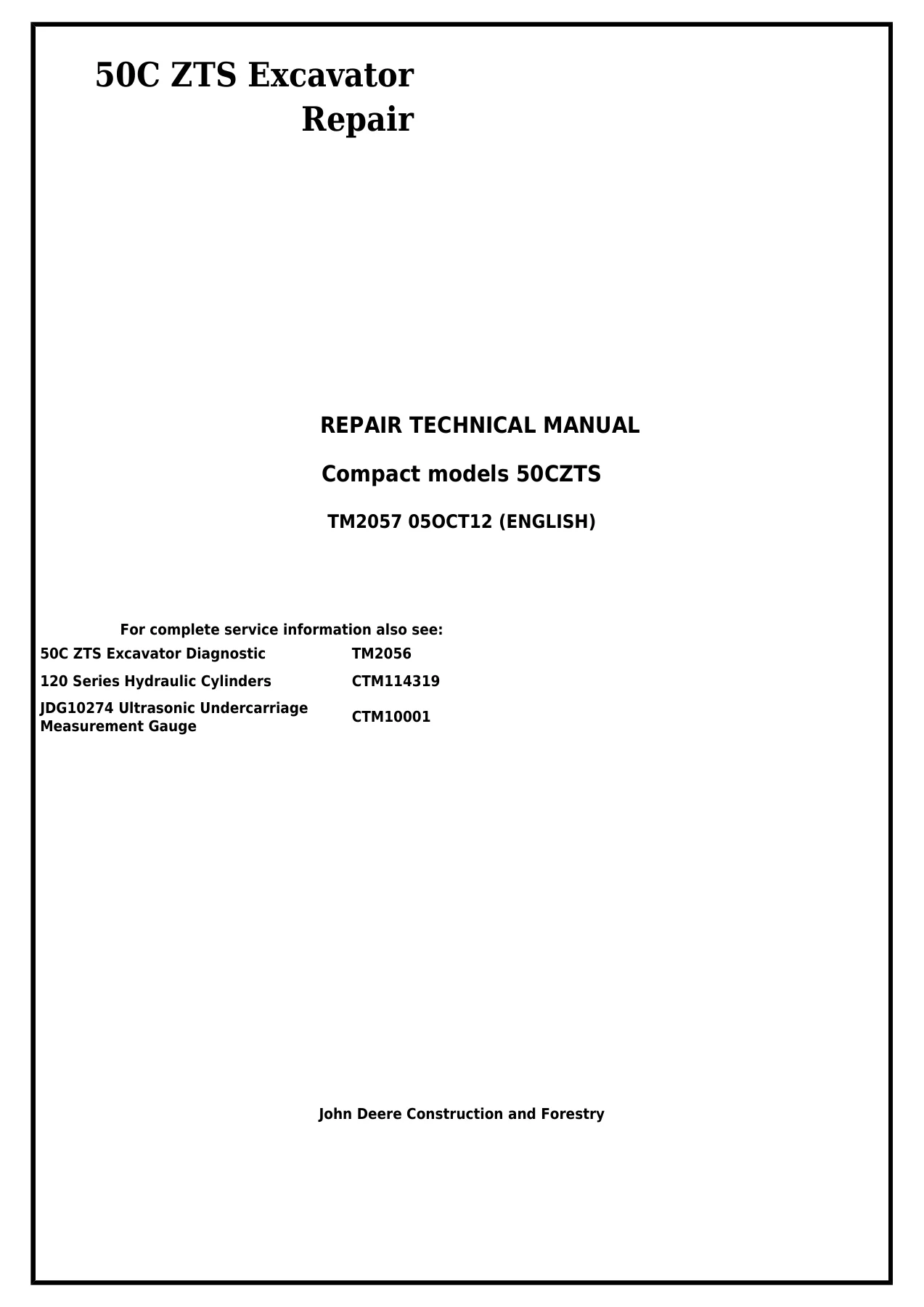
John Deere 50C ZTS Excavator Repair Technical Manual TM2057
Original price was: $37.95.$22.95Current price is: $22.95.
Complete John Deere 50C ZTS Excavator Repair Technical Manual TM2057 covering tracks, propel gearboxes, engine, cooling, operator’s station, blade, excavator frames, hydraulics and the swing/pivoting system. 427-page English PDF with procedures, torque values, wear limits and dealer-fabricated tool drawings for the compact 50CZTS excavator.
Description
John Deere 50C ZTS Excavator Repair Technical Manual — TM2057
The John Deere 50C ZTS Excavator Repair Technical Manual TM2057 is the full repair reference for the compact 50CZTS excavator. Published 05OCT12 in English, it takes a technician through component teardown, inspection, repair and reassembly across tracks, propel gearboxes, engine, cooling system, operator’s station, blade, excavator frames, hydraulic system and the swing/pivoting system. Every procedure is supported by the applicable torque values, wear limits, special tools and service specifications so a job can be carried through from start to finish without guesswork.
Because the 50C ZTS is a zero-tail-swing compact excavator, the repair work is often tight, heavily hydraulic and unforgiving of shortcuts. That is exactly why this John Deere 50C ZTS repair manual matters — it documents the correct disassembly sequence, the exact torque values for cap screws and fittings, the seal and bushing limits that decide whether a part is reused or replaced, and the tooling that keeps a rebuild safe.
What This 50C ZTS Repair Technical Manual Delivers
The TM2057 manual is organised in factory group numbers, the same way a dealer service department would work through a machine. It does not stop at describing a component — it gives the numbered legend, the exploded view, the specifications table and the tightening sequence in the same group, so a technician can go from diagnosis to reassembly in one place.
- Track system: track roller repair and rebuild, carrier roller removal, metal face seal inspection and reuse criteria, steel and rubber track removal, sprocket and front idler repair, track adjuster and recoil spring disassembly with the required compression tooling.
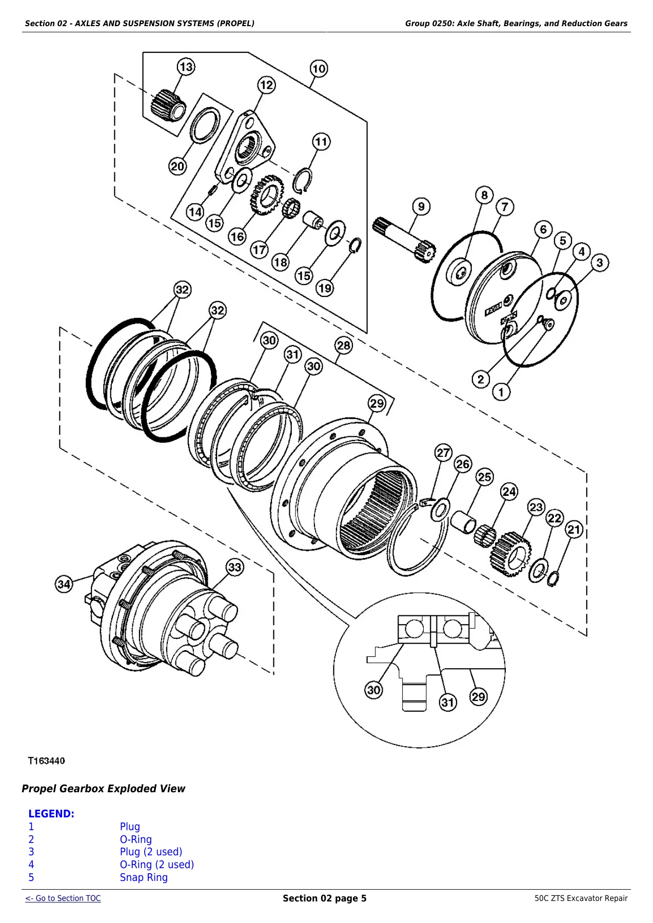
- Propel: gearbox and motor removal as an assembly, gearbox exploded views with planet carriers, ring gear and metal face seals, propel motor disassembly and the brake valve housing with park brake springs.
- Engine: exhaust manifold, water pump, cylinder head, cylinder block, rocker arm, camshaft, flywheel, crankshaft, piston and connecting rod, oil pump, thermostat, fuel injection pump and nozzle, and alternator — all with clearances and torque values.
- Engine auxiliary systems: glow plug service, fan belt tension, radiator and oil cooler removal, engine speed control cable, fuel shut-off solenoid and linkage, fuel tank and filter service, and the fuel system bleed procedure.
- Operator’s station: cab and canopy removal, platform, bonded and sliding window repair, seat, seat belt, heater and blower motor.
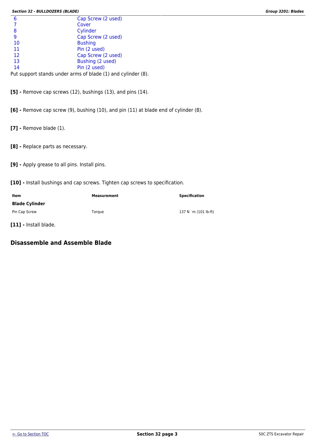
- Blade and excavator: blade repair and blade cylinder, bucket tooth shank welding, bucket links, arm, boom, boom swing, and pin and bushing inspection limits.
- Hydraulics: hydraulic pump removal and rebuild, dampener drive, solenoid valve manifold, pilot controllers, control valve section-by-section disassembly, hydraulic oil tank, and every cylinder — boom, arm, bucket and boom swing.
- Swing/pivoting: swing gearbox rebuild with bearing preload measurement, upperstructure removal, swing bearing replacement with race alignment, and swing motor with park brake.
- Dealer fabricated tools: dimensioned drawings for the ST4920 track recoil spring tool, the DFT1087 guard tool and the DFT1112 spacer.
Chapters Covered
- Section 00 — General Information: Safety; Torque Values
- Section 01 — Tracks: Track System
- Section 02 — Axles and Suspension Systems (Propel): Axle Shaft, Bearings, and Reduction Gears; Hydraulic System
- Section 04 — Engine: Removal and Installation
- Section 05 — Engine Auxiliary Systems: Cold Weather Starting Aids; Cooling System; Speed Controls; External Fuel Supply Systems
- Section 17 — Frame or Supporting Structure: Frame Installation; Chassis Weights
- Section 18 — Operator’s Station: Removal and Installation; Operator Enclosure; Seat and Seat Belt; Heating
- Section 32 — Bulldozers (Blade): Blades; Hydraulic System
- Section 33 — Excavator: Buckets; Frames; Hydraulic System
- Section 43 — Swing or Pivoting System: Mechanical Drive Elements; Hydraulic System
- Section 99 — Dealer Fabricated Tools: Dealer Fabricated Tools
Torque Values, Wear Limits and Inspection Data
One of the strongest reasons to keep the TM2057 manual on hand is the amount of measured data inside it. The torque value chapter alone covers Unified Inch and Metric bolt and screw torque tables by SAE and metric grade, straight fitting and special nut torque charts, O-ring seal fitting torque, flat face O-ring seal fitting torque, stud end O-ring seal torque, four-bolt flange fitting torque and metric series four-bolt flange fitting torque. Throughout the repair groups you get the component-specific values — track roller-to-frame cap screws, track shoe-to-link cap screws, sprocket cap screws, front idler yoke cap screws, cylinder head cap screws and their loosening/tightening sequences, bearing cap screws, connecting rod cap nuts with the torque-plus-turn figure, piston-to-rod values for each cylinder, and the piston ring end gaps, groove clearances, journal and bore diameters, runout limits and cylinder rod curvature tolerances that tell you whether a part is serviceable.
Diagnostic and Rebuild Depth
The John Deere 50C ZTS Excavator Repair Technical Manual TM2057 is not a lubrication chart with pictures. It is a bench-level rebuild guide. You get the metal face seal inspection method that decides whether a seal set can be reused as a matched pair, the track roller oil leakage test with its air pressure and hold time, the front idler axle and bushing measurement points, the propel motor piston-to-cylinder block bore clearance limit, the swing gearbox bearing rotational starting torque measurement using a spring scale, the Plastigage bearing clearance method for crankshaft journals and crank pins, valve spring free length, inclination and tension checks, cylinder head out-of-flat and grinding allowance, and the preheat temperatures and weld processes required for structural and tooth shank repair.
Safety content is woven throughout, including high-pressure hydraulic fluid warnings, pressurized hydraulic oil tank procedures, pressurized cooling system cautions, spring-loaded component warnings for the park brake and track recoil spring, and the correct procedure for disconnecting battery and controller wiring before welding on the machine.
Who This Repair Technical Manual Is For
This 50C ZTS repair manual is written for an experienced technician working on the compact 50CZTS excavator. It assumes familiarity with basic theory, general troubleshooting and standard maintenance practice. That makes it ideal for independent shops, fleet maintenance departments, owner-operators who do their own heavy repairs, and anyone rebuilding a track system, propel drive, hydraulic cylinder, control valve or swing gearbox on a 50C ZTS machine.
For complete service information on the machine, John Deere also cross-references the 50C ZTS Excavator Diagnostic TM2056, 120 Series Hydraulic Cylinders CTM114319, JDG10274 Ultrasonic Undercarriage and CTM10001 Measurement Gauge. This listing is for the TM2057 Repair Technical Manual.
Get the John Deere 50C ZTS Excavator Repair Technical Manual TM2057
With this John Deere 50C ZTS Excavator Repair Technical Manual in hand you can pull and rebuild a track roller, reseal a front idler, disassemble a propel gearbox, tear down and reassemble the hydraulic pump, service every pilot controller, rebuild the control valve section by section, reseal all five cylinders, and set up the swing gearbox bearing preload to the factory torque figure. Correct procedures and the right torque values are what separate a repair that lasts from one that comes back on the hook — and this manual gives you both, component by component.
IMAGES PREVIEW
The manual is delivered as an instant PDF download after payment, with no shipping and no waiting. It opens on any computer, tablet or phone and can be printed for the shop floor, so the page you need is right there next to the machine while you work.

Reviews
There are no reviews yet.