
John Deere 5200 5300 5400 Tractors Technical Manual TM1520 – Full Repair & Diagnostic PDF
Original price was: $34.95.$19.95Current price is: $19.95.
Complete John Deere TM1520 Technical Manual for 5200, 5300 and 5400 tractors. Covers engine, fuel/air, electrical, power train, steering, brakes, hydraulics and operator station repair, plus full diagnostics, tests and adjustments. Approximately 820 pages. Instant PDF download.
Description
John Deere 5200 5300 5400 Tractors Technical Manual TM1520
This John Deere 5200 5300 5400 Tractors Technical Manual TM1520 is the complete repair and diagnostic guide for the John Deere 5200, 5300 and 5400 tractors. Written for experienced technicians, it covers every major system on these machines — from the 3-cylinder diesel engine and dual clutch assembly through to the power train, steering, brakes and open-center hydraulic system. Everything needed for diagnosis, testing, adjustment and repair is contained in this single document, with detailed procedures, specifications, exploded views, wiring schematics and hydraulic schematics throughout.
File Details
- Manual Type: Technical Manual (Repair and Diagnostics)
- Brand: John Deere
- Models Covered: 5200, 5300, 5400 Tractors
- Document Number: TM1520
- Publication Date: 09MAR92
- Language: English
- Page Count: Approximately 820 pages
- File Format: PDF
Chapters Covered
- Section 10 — General Information: Safety, General Specifications, Repair Specifications, Fuel and Lubricants, Serial Number Locations, Features and Accessories
- Section 20 — Engine Repair: Engine, Cooling System
- Section 30 — Fuel and Air Repair: Fuel System, Air Intake System, Speed Control Linkage
- Section 40 — Electrical Repair: Battery/Starter/Alternator, Electrical System Components, Wiring Harness
- Section 50 — Power Train Repair: Clutch Housing, Dual Clutch Assembly, Collar Shift Transmission, Rear PTO Drive Shaft, Differential, Final Drives, Mechanical Front Wheel Drive, Creeper Assembly
- Section 60 — Steering and Brake Repair: Steering Repair, Brake Repair
- Section 70 — Hydraulic Repair: Hydraulic Pump and Filter, Rockshaft, Dual Selective Control Valve, Single (Third) Selective Control Valve
- Section 80 — Miscellaneous Repair: Front Axle—2WD, Wheels, 3-Point Hitch
- Section 90 — Operator Station Repair: Seat and Support, ROLL-GARD
- Section 210 — Test and Adjustment Specifications: Operational Checkout Procedures
- Section 220 — Engine Operation, Tests and Adjustments: Component Location, Theory of Operation, Diagnosis/Tests/Adjustments
- Section 230 — Fuel/Air Operation, Tests and Adjustments: Component Location, Theory of Operation, Diagnosis/Tests/Adjustments
- Section 240 — Electrical System Operation, Tests and Adjustments: Component Location, Theory of Operation, Diagnosis/Tests/Adjustments, Wiring Schematics
- Section 250 — Power Train Operation, Tests and Adjustments: Component Location, Theory of Operation, Diagnosis/Tests/Adjustments
- Section 260 — Steering and Brake Operation, Tests and Adjustments: Component Location, Theory of Operation, Diagnosis/Tests/Adjustments
- Section 270 — Hydraulic System Operation, Tests and Adjustments: Component Location, Theory of Operation, Diagnosis, Hydraulic Tests (without SCV), Hydraulic Tests (with SCV), Hydraulic Tests (all), Adjustments, Hydraulic Schematics
- Section 299 — Dealer Fabricated Tools: Instructions for building clutch finger gauges, adjustment tools and a final drive turning tool
The John Deere TM1520 technical manual is organized into two functional halves. The repair sections (20 through 90) tell you how to disassemble, inspect, assemble and install every major component on the 5200, 5300 and 5400 tractors. The diagnostic sections (210 through 270) help you identify failures quickly — each symptom-based procedure walks through test conditions, normal readings, and the exact steps to take when readings fall outside specification. The manual also includes a complete electrical wiring schematic, hydraulic schematics for both SCV and non-SCV configurations, and detailed test and adjustment specifications for every major system. This is the same technical documentation used by John Deere service technicians, covering both repair procedures and the diagnostic logic behind them.
Engine, Fuel and Air Systems
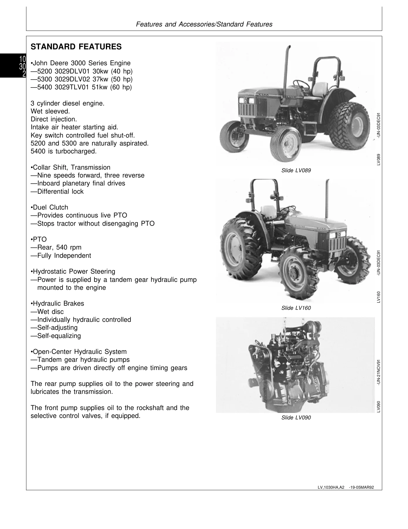
The engine repair section covers the 3029D and 3029T diesel engines used across the 5200, 5300 and 5400 tractors. Removal and installation procedures are covered for the complete engine assembly, along with cooling system repair including radiator removal and inspection, water pump repair, and thermostat replacement. The fuel and air repair section covers the fuel tank, fuel filter and primer pump, injection pump and nozzle repair (referenced to CTM8), air cleaner elements, and turbocharger removal and installation for the 5400. Speed control linkage inspection and repair is also included. The diagnostic section for the engine covers symptoms including hard starting, irregular running, rough running, low power, black or grey smoke, excessive white smoke, excess fuel use, excess noise or vibration, excess oil use or blue smoke, low oil pressure, incorrect coolant operating temperature, and oil in coolant or coolant in oil. Tests include radiator bubble, cooling system pressure, radiator cap pressure, engine oil pressure, cylinder compression pressure, and fuel shut-off solenoid check.
Electrical System
The electrical repair section covers battery, starter and alternator removal and installation, along with component-level replacement of the air filter restriction switch, coolant temperature sender, engine speed sensor, fuel shut-off solenoid, engine oil pressure switch, manifold heater, manifold heater relay, key switch, light switch, turn signal controller, instrument panel, rear PTO switch, neutral start switch, seat switch, and fuel level sender. Wiring harness replacement for both front and rear sections is documented with connector and terminal replacement procedures. The electrical diagnostics section walks through the starting system (normal operation and bypass attempt), manifold heater system, charging system, lighting system (turn signals, warning lights, tail light, headlights and instrument lights), instrument panel system (tachometer, fuel gauge, temperature gauge, hourmeter, oil pressure), PTO warning system, air filter restriction indicator, and optional equipment including work light, dual horn, and accessory relay and trailer connector. Each diagnostic procedure lists test location, normal reading, and what to check if the reading is not normal.
Power Train, Clutch and Transmission
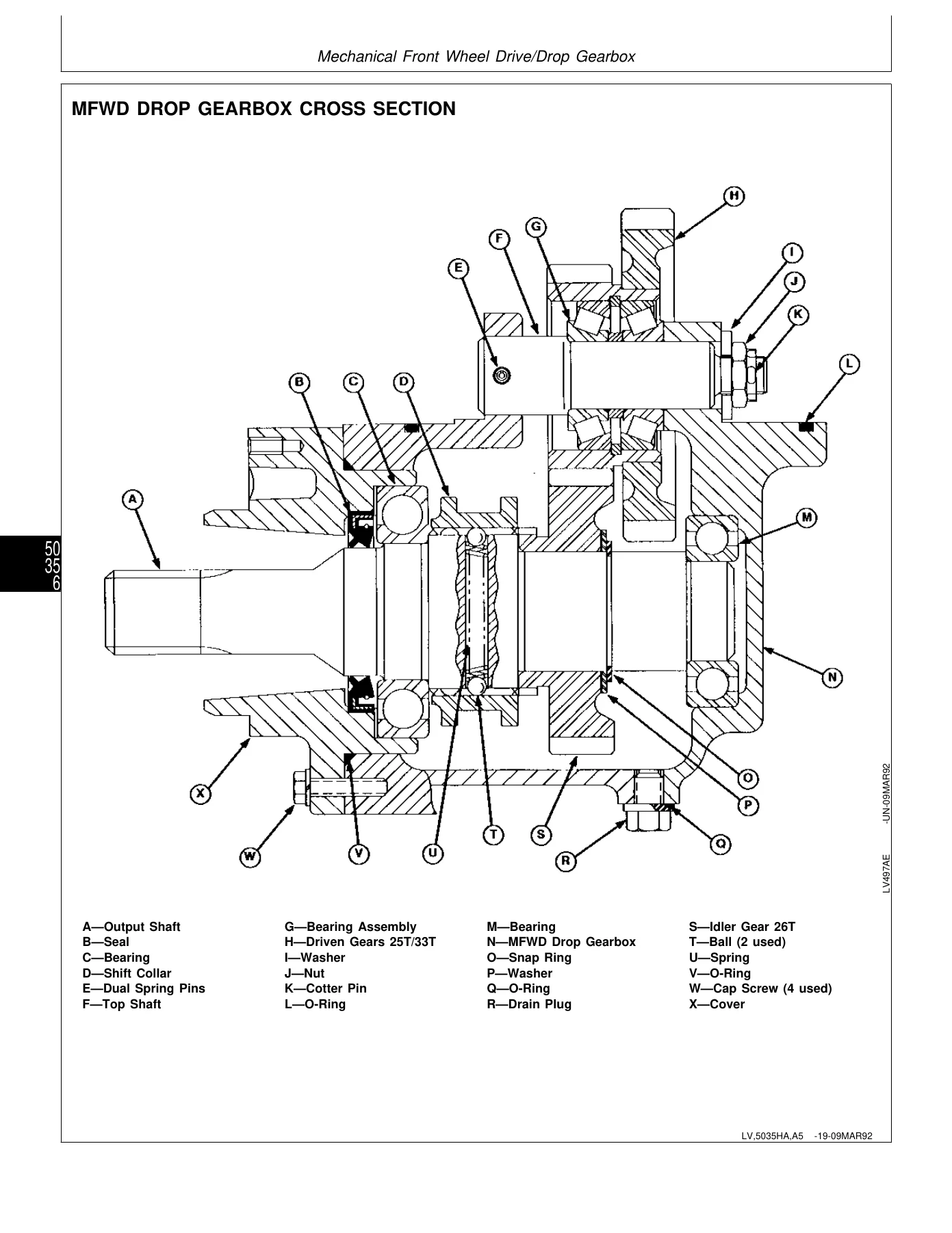
The power train repair section covers the clutch housing, dual clutch assembly, collar shift transmission, rear PTO drive shaft, differential, final drives, mechanical front wheel drive, and creeper assembly. Detailed procedures are included for separating the engine from the clutch housing, installing the engine to the clutch housing, replacing the clutch housing seal, and inspecting and repairing the clutch pedal and linkage. The dual clutch assembly is covered in depth with disassembly, inspection, assembly, and both traction and PTO clutch finger adjustment. The collar shift transmission section covers separation from the clutch housing, gear shift lever and range shift lever inspection and repair, transmission removal, disassembly, assembly, and installation, plus detailed procedures for the transmission top shaft, range reduction shaft, driven shaft, MFWD and range gears, and reverse idler shaft. The differential section includes disassembly, assembly, drive shaft removal and installation, differential lock assembly, cone point adjustment, and backlash adjustment. The final drive section covers the planetary drive assembly and axle shaft assembly. The MFWD section covers the drop gearbox, drive shaft, axle, axle supports, outer drive, swivel housing, axle shaft, differential carrier assembly, swivel pin bearing clearance adjustment, differential cone point adjustment, pinion bearing preload, pinion-to-ring gear backlash, and side bearing preload adjustment.
Steering, Brakes and Hydraulics
The steering and brake repair section covers the steering column and valve, steering valve disassembly, inspection and assembly, steering cylinder removal and installation for both 2WD and MFWD axles, tie rod assembly for both axle types, and inspection and replacement of steering hydraulic lines. The brake section covers the brake valve and pedals, brake valve disassembly, inspection and assembly, brake removal and inspection, brake installation, and inspection and replacement of brake hydraulic lines. The hydraulic repair section covers the hydraulic pump, hydraulic filter/manifold, rockshaft control lever, rockshaft control linkage, draft sensing support assembly, main relief valve, rockshaft surge relief valve, rate-of-drop valve, rockshaft control valve, rockshaft case, rockshaft lift arms, and rockshaft piston and cylinder. The dual selective control valve and single (third) selective control valve sections cover joystick and linkage inspection, control valve removal and installation, disassembly, inspection and assembly, and hydraulic hose inspection and replacement.
Diagnostics, Tests and Adjustments
The diagnostic sections are organized by symptom and system. Each procedure lists test conditions, test sequence, test location, normal reading, and the check or test to perform if the reading is not normal. The test and adjustment specifications section provides a comprehensive reference of values including engine operating temperature, radiator cap release pressure, valve clearance, cylinder pressure, oil pressure, thermostat opening temperatures, slow idle and fast idle speeds, injection pump timing, fan belt tension, turbocharger boost pressure, starter current draw and rpm, alternator output and regulated voltage, sensor resistances, clutch pedal free play, steering valve pressure relief, toe-in specifications, hydraulic pump flow and pressure, rockshaft rate-of-drop and lift time, and more. The hydraulic tests are divided into sections without SCV, with SCV, and all models — covering pump flow, main relief valve, SCV leakage, rockshaft leakage, and rockshaft lift cycle.
Dealer Fabricated Tools
The dealer fabricated tools section provides material lists and instructions for making several special tools referenced throughout the manual, including the PTO clutch finger height gauge, traction clutch finger height gauge, traction clutch finger height adjustment tool, and final drive turning tool. These are the tools needed to perform specific adjustments correctly when factory tools are not available.
Why This Manual Matters
When you are servicing a John Deere 5200, 5300 or 5400 tractor, having the correct specifications and procedures on hand is the difference between a repair that lasts and one that comes back. Torque values, clearances, adjustment procedures and diagnostic sequences are all documented here. The TM1520 technical manual covers the complete machine — engine, fuel system, air intake, electrical, clutch, transmission, differential, final drives, MFWD, steering, brakes, hydraulics, rockshaft, selective control valves, and operator station. It also includes the wiring schematics and hydraulic schematics needed to trace circuits and oil flow. Whether you are rebuilding a clutch, diagnosing an electrical fault, adjusting the rockshaft feedback linkage, or testing hydraulic pump output, this manual provides the step-by-step guidance and the specification values you need to get it right.
Delivery
The John Deere 5200 5300 5400 Tractors Technical Manual TM1520 is delivered as an instant PDF download after payment. No shipping, no waiting for a physical book. The file can be viewed on any device — computer, tablet, or smartphone — and pages can be printed for use in the workshop. Keep it on your phone in the shop, print the sections you need for a job, or store it on your computer for quick reference. Because it is a PDF, you can search for specific terms, jump to sections, and print only the pages you need. This is the complete manual, not an excerpt or a partial scan.
Reviews
There are no reviews yet.