
John Deere 544G, 624G, 644G 4WD Loader Operation and Test Technical Manual TM1529 – PDF Download
Original price was: $64.95.$44.95Current price is: $44.95.
Complete John Deere 544G, 544G LL, 544G TC, 624G, and 644G 4WD Loader Operation and Test Technical Manual TM1529. Instant PDF download with operational checkout procedures, diagnostics, theory of operation, adjustments, and tests for engine, electrical, power train, hydraulics, and air conditioning systems.
Description
John Deere 544G, 624G, 644G 4WD Loader Operation and Test Technical Manual TM1529
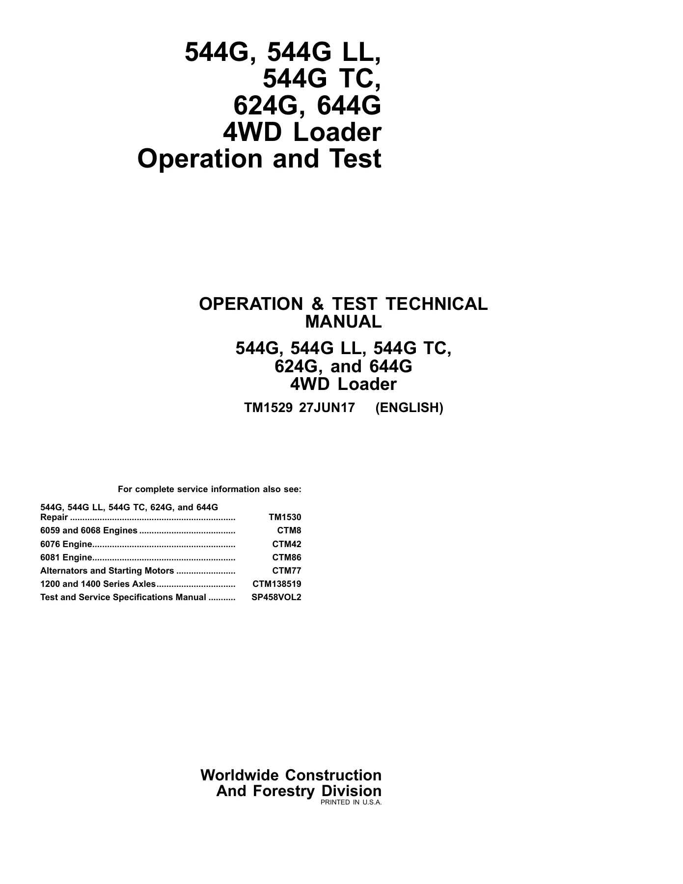
This is the complete John Deere 544G, 544G LL, 544G TC, 624G, and 644G 4WD Loader Operation and Test Technical Manual, document number TM1529, published 27JUN17 in English. It is the operation and test volume of the John Deere technical manual system — the diagnostic and testing companion to the repair manual TM1530. This PDF gives you the full operational checkout procedures, theory of operation, diagnostic information, adjustments, and test procedures for the 544G, 624G, and 644G 4WD loaders.
File Details
- Manual Type: Operation and Test Technical Manual (TM)
- Brand: John Deere
- Models Covered: 544G, 544G LL, 544G TC, 624G, 644G 4WD Loader
- Document Number: TM1529
- Date: 27JUN17
- Language: English
- Page Count: 700+ pages
- File Format: PDF
Chapters Covered
- Section 9000 — General Information
- Section 9005 — Operational Checkout Procedure
- Section 9010 — Engine Operation and Tests
- Section 9015 — Electrical System
- Section 9020 — Power Train Operation and Tests
- Section 9025 — Hydraulic System Operation and Tests
- Section 9031 — Air Conditioning System
Section 9000 — General Information
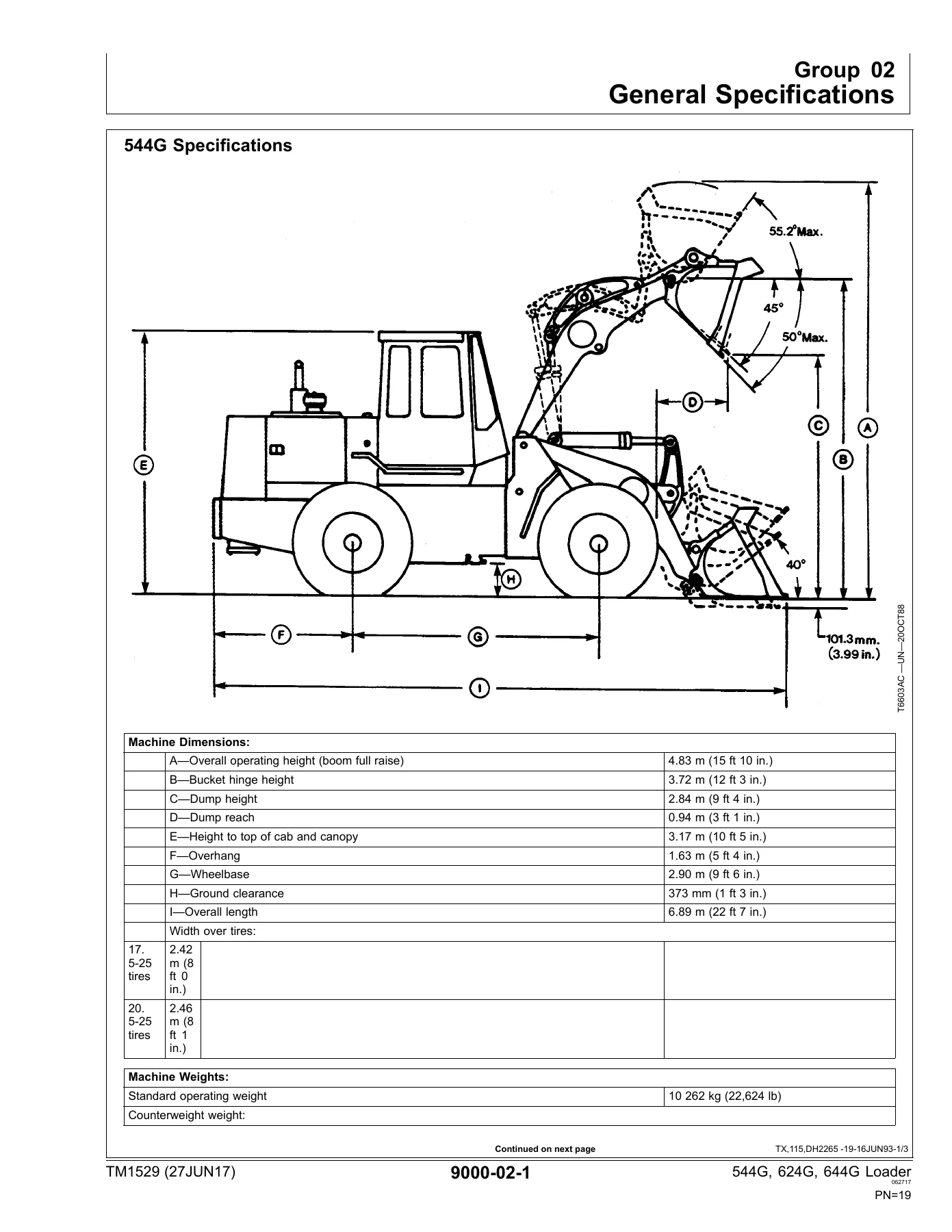
This opening section covers safety information, general specifications for each model (544G, 544G LL, 544G TC, 624G, 644G), drain and refill capacities, torque values including metric and unified inch bolt and screw torque charts, ROPS torque specifications, and service recommendations for O-ring boss fittings, flat face O-ring seal fittings, and metric and inch series four bolt flange fittings. It also covers fuel specifications, engine oil, hydraulic system oil and differential oil, transmission oil, grease, alternative and synthetic lubricants, and diesel engine coolant for engines with wet sleeve cylinder liners. This section establishes the safe working practices and the fluid and torque data you will rely on throughout every job.
Section 9005 — Operational Checkout Procedure
The operational checkout procedure provides a structured record sheet and step-by-step checks for the complete machine. It covers monitor indicator and gauge checks with the engine off and engine running, transmission controls, axle and engine linkages, neutral start switch, reverse warning alarm switch, brake system, clutch cut-off, differential lock checks, driving checks, hydraulic system checks, steering system checks, accessory checks, and cab component and vandal protection checks. This section is your first stop for verifying machine condition and isolating problems before installing test equipment.
Section 9010 — Engine Operation and Tests
Engine coverage includes theory of operation for the air cleaner and fuel system for the 544G and 624G (6059T and 6068T engines) and the 644G (6076A and 6081H engines). System operational checks cover cooling, air, lubrication, fuel, and engine speed and performance. Diagnostic information helps you diagnose engine malfunctions including hard starting, excessive smoke, and low power. Adjustments include injection pump timing, fan belt tension, slow and fast idle adjustment for the 544G and 624G and separately for the 644G, speed control linkage adjustment, fuel shut-off solenoid adjustment, primary fuel filter water draining, and fuel system bleeding. Tests cover air filter restriction indicator switch, radiator cap pressure, cooling system pressure, radiator air flow, engine power test using engine pulldown and turbocharger boost pressure, compression pressure, air intake system leakage, fuel supply pump pressure, and fuel line leakage.
Section 9015 — Electrical System
This section opens with system information, system diagrams, and sub-system diagnostics. It then provides detailed diagnostic procedures for the power circuit, charging circuit, start aid and fuel control circuit, park brake sensing/clutch cutoff/quickshift/backup alarm circuit, transmission control circuit, start circuit, park brake circuit, secondary steering circuit, differential lock and boom down circuit, switch inputs to monitor, electronic monitor signals, electronic monitor and gauge inputs, boom height kickout and return-to-dig circuit, front and rear wiper circuit, brake light circuit, heater/pressurizer circuit, air conditioning circuit, defroster pressurization circuit, turn signal and four-way flasher circuit, cab and canopy work light circuit, drive light and dome light circuit, door release/radio/horn/rotary beacon circuit, and pin disconnect/ride control/spare circuit. The references group covers battery specifications, battery operation and testing, starter operation, alternator operation for the 95 amp or 135 amp Bosch unit, accessing monitor service code display, monitor service code interpretation, programming the monitor display to match the machine, calibrating the tachometer, transmission electrical circuit test procedure, and transmission sensor adjustment.
Section 9020 — Power Train Operation and Tests
Power train theory of operation covers clutch engagement and solenoid activation charts, drive dampener, torque converter operation, transmission operation in neutral and in each forward and reverse gear, clutch operation, transmission hydraulic components and system, transmission pump operation, transmission control valve components and modulation for both the five-solenoid and six-solenoid valve, thermal bypass valve operation, TeamMate II axle operation, differential lock operation including the hydraulic differential lock air boost system and turbocharger boost, axle shaft and housing, axle disconnect operation, brake hydraulic system operation, brake pump operation and pressure compensator, brake accumulator operation, wet chambered brake valve operation, park brake operation, pressure reducing valve operation, and hydraulic tank operation. System operational checks cover brake system, clutch cut-off, differential lock, front axle disconnect, and transmission checks. Diagnostic information covers transmission, service brake, differential/axle, drive line, and park brake malfunctions. Adjustments include front axle disconnect, clutch cut-off, park brake, external service brake inspection, hydraulic brake bleeding, charging the brake accumulator, brake pump and differential lock system oil clean-up, and transmission sensor adjustment. Tests include transmission pump flow, transmission system pressure, element leakage and shift modulation, transmission lube pressure, converter relief pressure, converter-in pressure, converter-out pressure and flow, transmission oil cooler backflush, transmission oil cooler restriction, pressure reducing valve manifold leakage, transmission oil cooler thermal bypass valve, transmission oil cooler bypass valve pressure, torque converter stall speed, brake pump flow, brake pump standby pressure, brake accumulator precharge, brake valve pressure, brake valve leakage, brake accumulator inlet check valve leakage, park brake pressure, differential lock pressure, differential lock leakage, axle bearing adjustment, and no-spin differential.
Section 9025 — Hydraulic System Operation and Tests
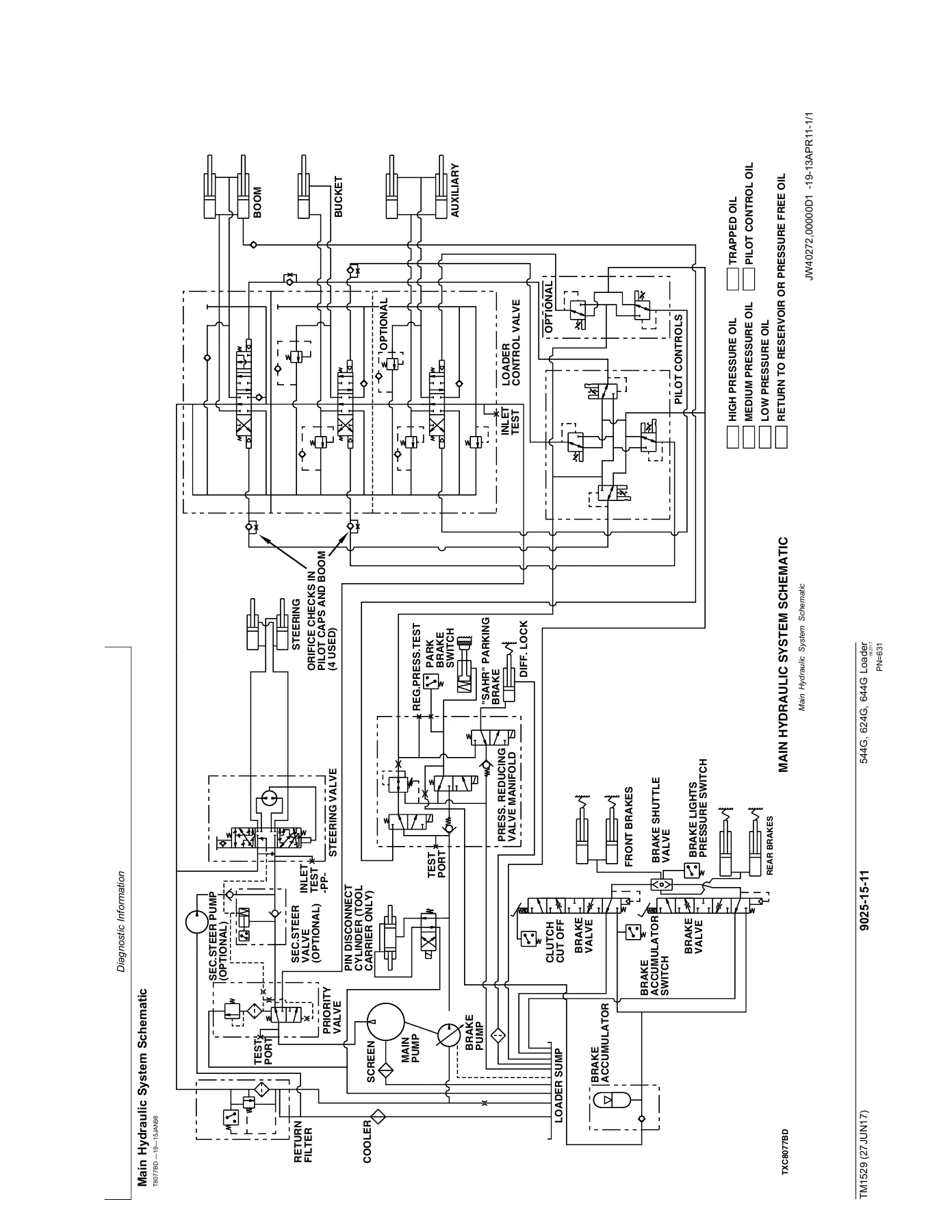
Hydraulic theory of operation covers main hydraulic pump operation, steering system components, steering circuit operation for a right turn, priority valve operation, steering valve operation, steering cylinder operation, secondary steering system operation, secondary steering inlet manifold operation, loader hydraulic system operation, pressure reducing valve for secondary boom lower, pilot controller operation for serial number ranges before and after 563543, boom section operation, bucket and boom section pilot orifice check valve, bucket section operation for the 544G/624G/644G and for the 544G TC and 544G LL, auxiliary section operation, system relief valve, circuit relief valve, anti-cavitation valve, loader cylinder information, return filter operation, hydraulic reservoir operation, pin disconnect circuit operation for the 544G TC, and ride control operation in the on and off positions. System operational checks cover the hydraulic system and steering system. Diagnostic information helps you diagnose hydraulic system malfunctions. Adjustments include hydraulic oil clean-up using a portable filter caddy, boom height kickout adjustment, return-to-dig adjustment, and ride control accumulator discharge, gas charge, and draining procedures. Tests include main hydraulic pump flow, loader system and circuit relief valve pressure, hydraulic system restriction, loader cylinder drift, boom and bucket cylinder leakage, hydraulic oil cooler restriction, steering valve leakage, steering valve drift, priority valve pressure, priority valve LS port flow, priority valve relief cartridge leakage, secondary steering pump relief valve pressure, secondary steering manifold primary and secondary check valve leakage, pilot control valve pressure for both serial number ranges, pressure reducing valve pressure, cycle time, hydraulic oil filter inspection, pin disconnect solenoid valve leakage, and pin disconnect cylinder leakage.
Section 9031 — Air Conditioning System
Air conditioning coverage includes proper refrigerant handling, R12 and R134a refrigerant cautions, refrigerant theory of operation, air conditioner circuit operational information and theory, air conditioning circuit schematic, defroster pressurization circuit, heater/pressurizer circuit, receiver/dryer operation, expansion valve operation, compressor relief valve operation, and temperature control. Operational checks include visual inspection of components, system operating checks, system performance checks, and air conditioner electrical circuit checks. Diagnostic information covers air conditioning electrical malfunctions. Adjustments cover R12 and R134a component oil charge, evacuation and charging station installation, recovering, evacuating and charging procedures for both refrigerants, and compressor belt tension. Tests include the R12 and R134a air conditioning system test, operating pressure diagnostic chart, pressure diagnostic chart, low pressure switch test, high pressure switch test, clutch cycle switch, leak testing, and refrigerant hoses and tubing inspection.
Why This John Deere 544G, 624G, 644G Operation and Test Manual Matters
When a 544G, 624G, or 644G loader comes into your shop with a transmission that won’t shift correctly, a hydraulic function that drifts or stalls, a brake system that won’t hold, or an electrical fault that keeps the machine from starting, guessing costs time and money. This manual gives you the factory test procedures and diagnostic charts that let you isolate the problem logically instead of throwing parts at it. The operational checkout procedure alone is worth the download — it walks you through every system on the machine in a sequence designed to catch routine failures fast, before you ever connect a gauge or a multimeter. For the engine, you get compression pressure specs, turbocharger boost pressure specs, fuel supply pump pressures, and injector timing values. For the power train, you get transmission system pressure specs, element leakage limits, torque converter stall speeds, clutch pack drag checks, and shift modulation times. For the hydraulics, you get pump flow rates, relief valve pressures, cylinder drift limits, and priority valve test procedures. For the electrical system, you get a full diagnostic path for every circuit on the machine, including the monitor service codes and the procedure to access them. And for air conditioning, you get the pressure diagnostic charts that tell you exactly what a low-side or high-side reading means. This is not a generic repair guide — it is the John Deere operation and test manual for these specific machines, and it includes the serial number breakpoints that matter when a running change was made to the transmission control valve, the engine, or the monitor programming. Whether you are a professional technician, a fleet maintenance manager, or an owner who does their own service work, having the correct specifications and test procedures on hand is what separates a quick, correct repair from a comeback.
IMAGES PREVIEW
Instant PDF Download — No Shipping, No Waiting
This John Deere 544G, 624G, 644G 4WD Loader Operation and Test Technical Manual TM1529 is delivered as an instant PDF download. There is no physical book to ship and nothing to wait for. As soon as your order is complete, you can download the file and start using it. The PDF works on any device — desktop, laptop, tablet, or smartphone — and you can print the pages you need for the shop floor. Whether you are diagnosing a fault code, setting up a pressure gauge, or verifying a torque value, the information is right there when you need it. Add this manual to your library today and give yourself the same operation and test documentation that John Deere published for these loaders.
Reviews
There are no reviews yet.