
John Deere 6110M 6120M 6125M 6130M 6135M 6140M 6145M 6155M 6175M 6195M Diagnosis Technical Manual TM408419 2015
Original price was: $129.95.$79.95Current price is: $79.95.
Comprehensive 5,518-page diagnosis technical manual for John Deere 6110M, 6120M, 6125M, 6130M, 6135M, 6140M, 6145M, 6155M, 6175M and 6195M tractors. Covers diagnostic trouble codes, observable symptoms, electrical and hydraulic schematics, control units, engine and aftertreatment diagnosis, transmission, steering, brakes, hydraulics, suspension, cab systems, tests, adjustments and component information. Manual TM408419, dated 01DEC15, in English.
Description
John Deere 6110M-6195M Diagnosis Technical Manual TM408419
This 5,518-page John Deere diagnosis technical manual is a deep troubleshooting reference for 6110M, 6120M, 6125M, 6130M, 6135M, 6140M, 6145M, 6155M, 6175M and 6195M tractors. Published as TM408419 and dated 01DEC15, it is written for experienced technicians and is organized around the actual diagnostic process: identify symptoms or diagnostic trouble codes, understand system operation, follow schematics, perform operational and circuit checks, test components, make adjustments and trace faults to their likely cause. The manual’s foreword specifically describes diagnostic technical manuals as on-the-job guides containing information to diagnose, analyze, test and repair equipment, while also referencing separate repair technical manuals where component service instructions are required.
File Details
- Manual type: Diagnosis Technical Manual
- Brand: John Deere
- Models: 6110M, 6120M, 6125M, 6130M, 6135M, 6140M, 6145M, 6155M, 6175M, 6195M
- Language: English
- Page count: 5,518 pages
- File format: PDF
- Document number: TM408419
- Date: 01DEC15
Chapters Covered
- Section 210 – GENERAL
- Section 211 – DIAGNOSTIC TROUBLE CODES
- Section 212 – OBSERVABLE SYMPTOMS AND SYSTEM DIAGNOSTICS
- Section 220 – ENGINE
- Section 230 – FUEL, AIR INTAKE AND COOLING SYSTEMS
- Section 239 – FUEL, AIR INTAKE, AND COOLING SYSTEMS – COMPONENT INFORMATION
- Section 240 – ELECTRICAL SYSTEM
- Section 245 – ELECTRONIC CONTROL UNITS
- Section 249 – ELECTRICAL CONNECTORS, WIRING HARNESSES, AND COMPONENTS
- Section 250A – DRIVE TRAIN (WITHOUT TRANSMISSION)
- Section 250C – POWRQUAD™ TRANSMISSION
- Section 259 – DRIVE TRAIN – COMPONENT INFORMATION
- Section 260A – STEERING
- Section 260B – BRAKES
- Section 269 – STEERING AND BRAKES – COMPONENT INFORMATION
- Section 270 – HYDRAULIC SYSTEM
- Section 279 – HYDRAULIC SYSTEM – COMPONENT INFORMATION
- Section 280A – MACHINE-SPECIFIC SYSTEMS
- Section 280B – SUSPENSION SYSTEMS
- Section 289 – SUSPENSION SYSTEMS – COMPONENT INFORMATION
- Section 290 – OPERATOR’S CAB
- Section 299 – OPERATOR’S CAB – COMPONENT INFORMATION
- Section 300 – SPECIAL TOOLS
General diagnostic references and safe test practice
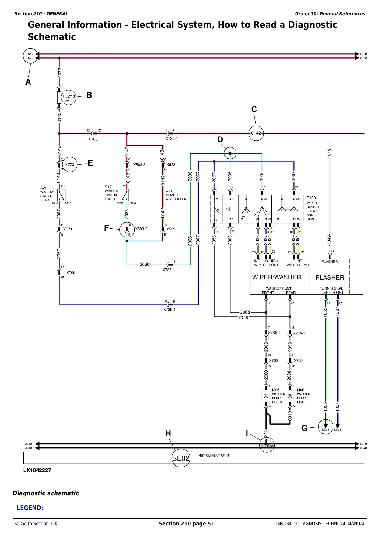
Section 210 establishes the working methods used throughout the John Deere 6110M-6195M diagnosis manual. Along with machine and service safety, it includes inch and metric fastener torque charts, hydraulic fitting torque values, hydraulic and electrical designators, lead-number and color-code references, schematic symbols and guidance for reading diagnostic schematics. It also lays out systematic electrical troubleshooting methods for high-resistance, open, grounded and shorted circuits, connector inspection, circuit and harness testing, load testing, intermittent faults and a seven-step electrical test procedure. These references matter when a fault is not solved by simply reading a code and replacing a component.
Diagnostic trouble codes
Section 211 is a major portion of TM408419 and organizes diagnostic trouble codes by control software. It covers numerous controllers and software groups including AIC, BLC, CCU, ECU, EIC, FCC, HCC, JDL, OIC, PDU, PTF, PTQ, PTR, RPT, SCO, SFA, TEC, TEI, TIH, TIQ, VTV, XMC and XSC. Individual code entries describe the fault condition, control-software reaction and step-by-step diagnostic actions. The manual repeatedly directs the technician through code verification, operational checks, relevant circuit tests, CAN Bus checks, programming or calibration procedures and follow-up testing, making it useful for faults that involve several electronically linked tractor functions rather than a single isolated component.
Observable symptoms and system diagnostics
Section 212 provides another route into troubleshooting when a tractor has a functional complaint but the problem is better approached by symptom. The section is divided across the engine; fuel, air-intake and cooling systems; electrical system; electronic control units; drive train; PowrReverser™ and PowrQuad™ transmissions; steering; brakes; hydraulic system; suspension systems and operator’s cab. This gives the technician a structured path from what the operator observes to the system checks and diagnostic procedures needed to narrow down the cause.
Engine, exhaust aftertreatment, fuel, air intake and cooling
The engine section includes exhaust aftertreatment theory of operation plus tests and adjustments. The adjoining fuel, air-intake and cooling chapters explain the fuel system, air-intake system, cooling system and cold-weather starting system, then move into tests and adjustments and component information. Component-information groups cover fuel-system components, cooling-system components, the charge-air circuit and cold-start system. The diagnostic trouble-code material also reaches deeply into electronically monitored engine and aftertreatment faults such as fuel rail pressure, oil pressure, coolant temperature and pressure, turbocharger/VGT functions, EGR, injectors, DEF dosing, DPF and SCR-related conditions.
Electrical system, schematics and tractor circuits
Electrical diagnosis is one of the strongest parts of this 2015 John Deere M Series tractor manual. Section 240 begins with general information and theory of operation, followed by electrical schematics and circuit-specific diagnostic groups. Coverage includes starter and charging circuits, external cold-start aid, lighting and worklights, cab lights, turn signals, seat circuits, acoustic alarms, wipers, heater/ventilation/air conditioning, sockets, radio and accessories. It also includes diagnostic material for implement CAN Bus functions, AutoTrac™, radar, JDLink™ Service ADVISOR™ Remote, electronic engine control, immobilizer, fuel-system electronics, transmission electronics, differential lock, front-wheel drive, rear and front PTO, brakes, rear hitch, E-SCV selective control valves, suspended front-wheel drive axle, front loader, display, LIN Bus modules, bus systems, ground connections and electronic control units. The schematics identify connectors, lead numbers, splice points, switches, loads, power supplies and grounds so electrical faults can be traced rather than guessed at.
Electronic control units, programming, tests and calibrations
Section 245 concentrates on electronic control units. It contains general ECU information, interactive tests and calibrations, programming information, theory of operation and controller-specific groups. For a tractor with electronic communication, configuration or calibration concerns, this part of the John Deere 6110M 6120M 6125M 6130M 6135M 6140M 6145M 6155M 6175M 6195M diagnosis technical manual provides the links between software faults, controller behavior, circuit checks and the procedures used to confirm whether programming, calibration, wiring or a component is actually responsible.
Connectors, harnesses, sensors and electrical components
Section 249 is a large component-location and identification resource. It covers electrical assemblies, sensors, miscellaneous electrical devices, fuses, relays and diodes, power supply and alternator components, control and signal devices, motors, resistors, switches, wiring harnesses, connectors, ground points, solenoid valves and solenoids. This complements the circuit tests by helping the technician identify the correct component, connector or harness location before measurements are taken. The manual’s general guidance also stresses proper connector handling, clean terminals and logical verification before condemning a control unit.
Drive train and PowrQuad™ transmission diagnostics
The drive-train chapters include operational checks, theory of operation, tests and adjustments for the drive train without transmission, plus dedicated PowrQuad™ transmission general information, operational checks, theory of operation, schematics, tests and adjustments. Component-information groups support both drive-train and PowrQuad™ diagnosis. Observable-symptom material also includes PowrReverser™ transmission diagnostics, while the electrical-system section contains circuit diagnostics for transmission-related electronics. Together these sections help separate control, electrical, hydraulic and mechanical symptoms before repair work is started.
Steering and brake systems
Steering and brakes are treated as full diagnostic systems rather than brief maintenance topics. Each section includes general information, operational checks, theory of operation, schematics and tests and adjustments, followed by dedicated component-information chapters. That structure is especially useful when the same complaint could originate from hydraulic operation, an electrical command, a sensor or a mechanical component: the technician can compare system behavior against the schematic and prescribed test sequence before deciding where the fault lies.
Hydraulic system, hitch and valve diagnostics
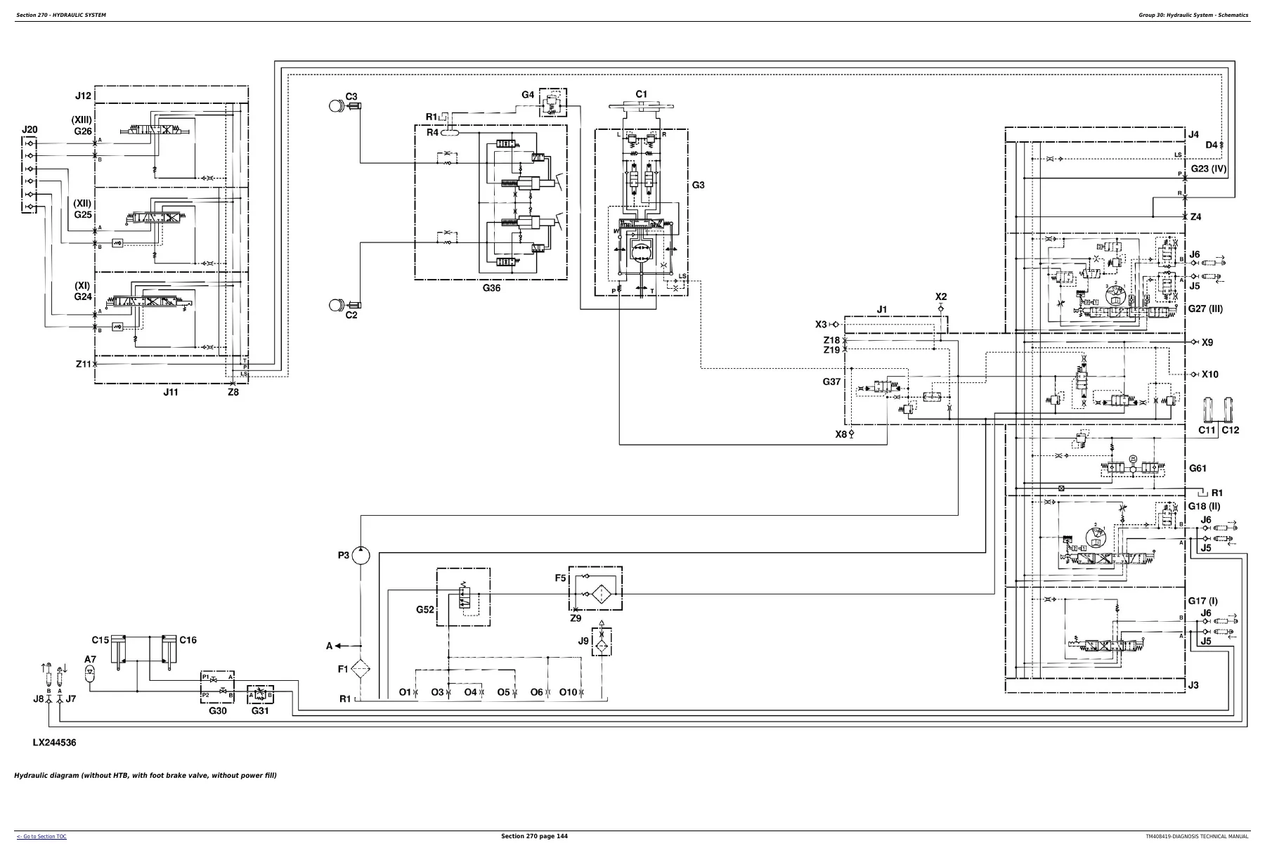
Section 270 provides broad hydraulic-system diagnosis with general information, operational checks, theory of operation, schematics, tests and adjustments. It breaks out the oil filter, additional oil reservoir, charge pump and hydraulic pump, rear hitch, front hitch, selective control valves (SCVs) and independent control valves (ICVs). The hydraulic schematics show circuit relationships and component designators in detail, while Section 279 adds component information. For hydraulic complaints involving pressure, flow, hitch operation or remote valve functions, this combination of theory, schematics and measured checks gives a far more disciplined route to the cause than trial-and-error parts replacement.
Machine-specific systems, suspension and operator’s cab
Further chapters cover machine-specific operational checks and tests, suspended front-wheel drive axle theory, schematics and adjustments, mechanical cab suspension, and component information for both suspension types. The operator’s cab section includes operational checks, theory of operation, tests and adjustments, with separate air-conditioning component information. These areas make TM408419 useful beyond engine and transmission faults, particularly when the complaint involves ride systems, cab functions, HVAC operation or machine-specific equipment.
Special tools and diagnostic workflow
The final section identifies special-tool information used by the procedures, and earlier chapters name required diagnostic tools where applicable. This is important because many tests in the manual are designed around controlled measurements, connector probing, electrical loading, calibration or system checks rather than visual inspection alone. The result is a manual intended to support repeatable diagnosis: verify the complaint, follow the correct schematic or test, compare the result with the stated condition, repair the identified fault and perform the operational check again.
A serious diagnostic reference for these John Deere M Series tractors
If you work on a 6110M, 6120M, 6125M, 6130M, 6135M, 6140M, 6145M, 6155M, 6175M or 6195M, this John Deere TM408419 diagnosis technical manual gives you the fault-code logic, system theory, wiring and hydraulic schematics, component information, operational checks, tests, adjustments and calibration references needed to diagnose problems systematically. It is particularly valuable when a symptom crosses several systems or when an electronic code must be traced through wiring, connectors, CAN communication, sensors and control software before the real cause is confirmed.
This is a diagnosis technical manual, so component teardown and repair instructions may be referenced to separate repair technical manuals where required. Its strength is helping you determine what has failed, why the system is behaving incorrectly and which checks should be completed before repair work begins. Using the specified diagnostic sequence and values can reduce unnecessary parts replacement, prevent missed electrical or hydraulic causes and give technicians a reliable reference while troubleshooting in the workshop or in the field.
IMAGES PREVIEW
After purchase, the complete manual is delivered as an instant PDF download. There is no shipping delay: open it on a computer, tablet or phone, keep it available beside the tractor, and print the pages or procedures you need for the job.
Reviews
There are no reviews yet.