
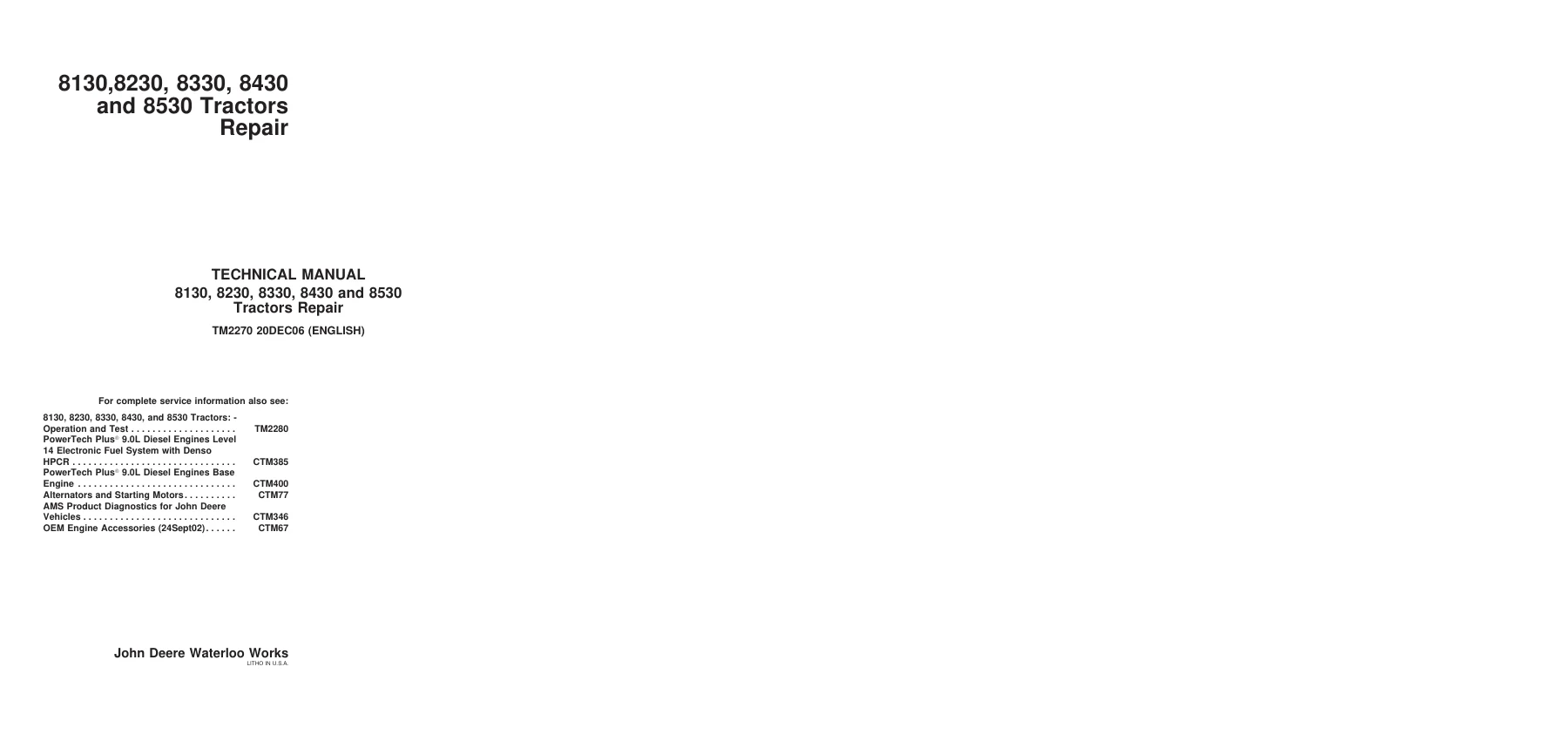
John Deere 8130, 8230, 8330, 8430 and 8530 Tractors Service Repair Technical Manual (TM2270)
Original price was: $39.95.$24.95Current price is: $24.95.
Factory service repair technical manual TM2270 for John Deere 8130, 8230, 8330, 8430, and 8530 tractors. Provides comprehensive mechanical overhaul, component removal, teardown, inspection, assembly, and tightening specifications for PowerShift and AutoPowr/IVT transmissions, Independent Link Suspension (ILS), MFWD axles, 9.0L PowerTech Plus engines, hydraulics, and electrical systems.
Description
Complete Workshop Service Repair Manual for John Deere 8130, 8230, 8330, 8430, and 8530 Tractors (TM2270)
The John Deere 8130, 8230, 8330, 8430 and 8530 Tractors Service Repair Technical Manual (TM2270) is the definitive workshop reference engineered specifically for service technicians, mechanics, and agricultural operators maintaining 8030 Series row-crop tractors. Designed for complete mechanical overhauls, major component teardown, and field reassembly, this comprehensive repair manual delivers step-by-step disassembly sequences, essential tool requirements, wear tolerances, and exacting torque limits. Whether handling an engine replacement on an 8130 tractor or overhauling an Independent Link Suspension (ILS) axle on an 8530, this official factory documentation delivers precision technical guidance.
Document & File Details
- Document Title: 8130, 8230, 8330, 8430 and 8530 Tractors Repair Technical Manual
- Manual Publication Number: TM2270 (20DEC06)
- Manufacturer: John Deere Waterloo Works
- Machine Coverage: John Deere 8130, 8230, 8330, 8430, and 8530 Tractors
- Engine Architecture: 9.0 L (548 cu in.) PowerTech Plus In-Line 6-Cylinder Diesel Engine
- Primary Language: English
- Page Count: 1618 pages
- Format: High-quality digital PDF printable on all devices
Chapters Covered in TM2270
This technical service manual is organized into logical, component-specific sections structured to guide service technicians through repairs efficiently:
- SECTION 10 — General Information
- Group 05 — Safety Precautions, Safe Maintenance Practices, and High-Pressure Fluid Hazards
- Group 10 — General Specifications, Overall Dimensions, Metric & Unified Inch Torque Charts, Sealants/Adhesives Cross-Reference, Glossary, and Snap-To-Connect (STC) Fittings
- SECTION 20 — Engine
- Group 00 — Component Removal and Installation (Engine, Front Frame, Support Hardware, Hoist Rigging)
- Group 05 — Engine Repair, Flywheel Dampener Replacement, and Inertia Ring Service
- SECTION 30 — Fuel and Cooling Systems
- Group 05 — Diesel Fuel System (Fuel Tank Removal/Installation, Cab Mount Support, Fuel Bleeding)
- Group 10 — Air Intake System (Intake Piping, Aspirator Pipes, Clamps, and Charge Air Ducts)
- Group 15 — Engine Cooling System (Radiator Testing, Auxiliary Drive Belts, Tensioners, VARI-COOL Fan Drive & Driven Assembly Overhaul)
- Group 20 — Coolers and Air Conditioning Condenser (Fuel Cooler, A/C Condenser, Aftercooler, Hydraulic Oil Cooler)
- SECTION 40 — Electrical
- Group 05 — Connectors (AMP, Blade Terminal, CINCH Wedgebox & Flexbox, CPC, Deutsch, ITT, MATE-N-LOC, Metri-Pack, Molex, Sumitomo, Tyco, Weather Pack, Yazaki)
- Group 10 — Wiring Harness Routings (MFWD & ILS Chassis, Cab, Console, Roof, Transmissions, Active Seat, AutoTrac, Convenience Outlets)
- Group 15 — Charging Circuit (Alternator Replacement and Exploded Views)
- Group 20 — Starting Circuit (Starter Motor, Relays, Master Fuse, and Neutral Start Switches)
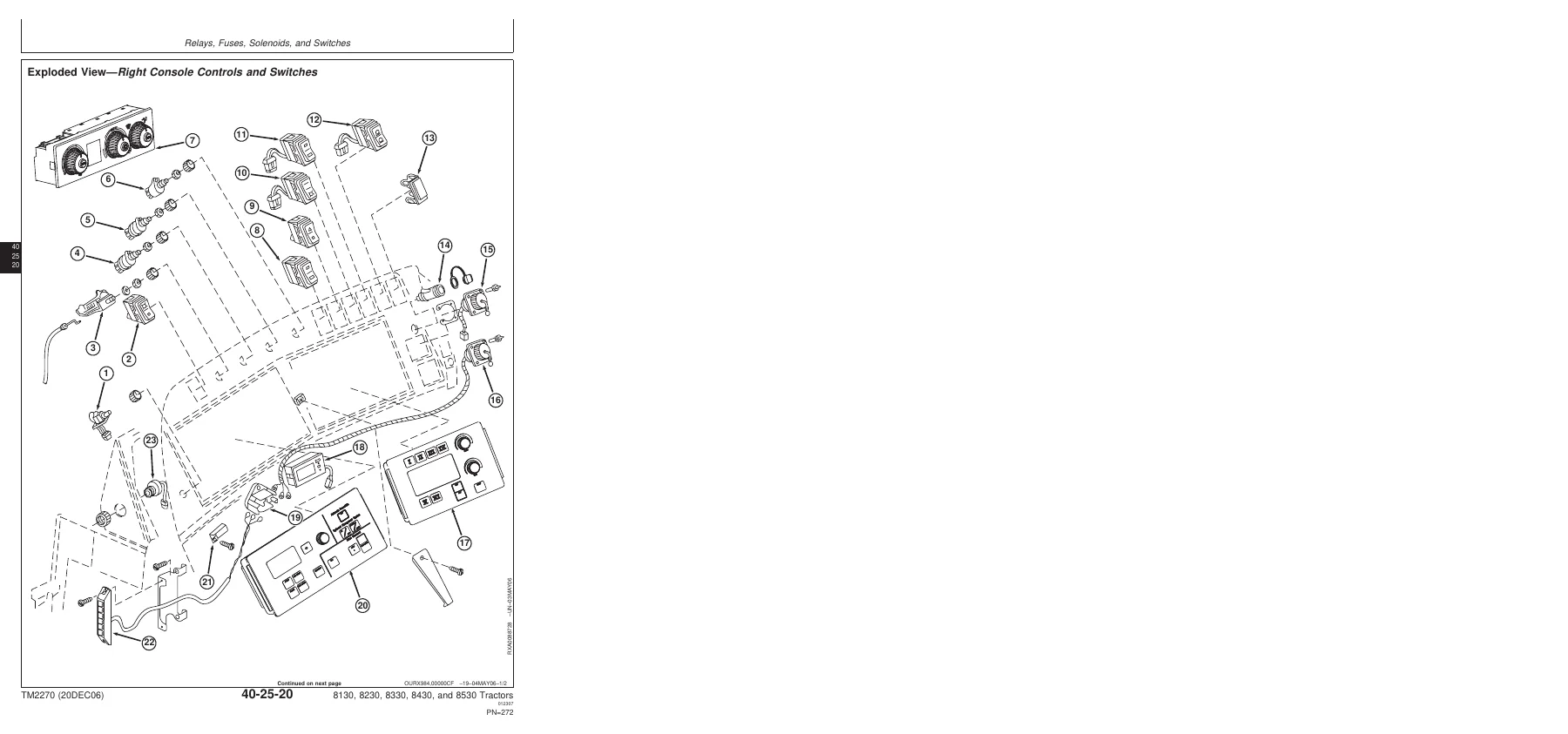
- Group 25 — Relays, Fuses, Solenoids, and Switches (Load Center Schematics, Shift Valves, MFWD, Park Brake, Console Controls)
- Group 30 — Monitoring Systems and Sensors (CommandCenter ICU, SCV Setup Panel, Steering Column Module, Wheel Angle, Speed, Draft, and CLIMATRAK Sensors)
- Group 35 — Armrest Control (ACU Replacement, Speed Levers, PST & IVT Shifter Assemblies, SCV & Hitch Levers)
- Group 40 — Implement and Accessory Connectors (Seven-Terminal Socket, GreenStar, Auxiliary Outlets)
- Group 45 — Convenience and Accessory Components (Seat Compressors, Blowers, Wipers, Auxiliary Heaters)
- SECTION 50 — PowerShift Transmission (PST)
- Group 00 — Component Removal and Installation
- Group 05 — Miscellaneous Repair
- Group 10 — Transmission Overhaul
- SECTION 51 — AutoPowr / IVT Transmission
- Group 00 — Component Removal and Installation
- Group 10 — General Repair Procedures
- Group 15 — In-Tractor Repairs
- Group 20 — Transmission Repair & Hydrostatic Module Service
- Group 30 — Transmission Assembly & Shimming
- SECTION 56 — Drive Systems
- Group 00 — Component Removal and Installation
- Group 05 — Rear Differential and Input Quill
- Group 10 — Primary and Secondary Brakes
- Group 15 — Final Drives
- Group 20 — Rear PTO
- Group 25 — Hydraulic Pump Drive
- Group 30 — MFWD Clutch
- Group 35 — Drivelines
- SECTION 57 — MFWD Axles
- Group 00 — Component Removal and Installation
- Group 05 — Final Drives
- Group 10 — Axle Housing
- Group 15 — Differential
- Group 20 — Input Gear Train
- Group 25 — Oscillation
- SECTION 58 — INDEPENDENT LINK SUSPENSION (ILS) Axle
- Group 00 — Component Removal and Installation
- Group 05 — Controls & Accumulators
- Group 10 — Final Drives
- Group 15 — Drive Shafts
- Group 20 — Differential
- Group 25 — Steering & Suspension Cylinders
- Group 30 — Suspension Control Assembly
- SECTION 59 — 1500 Series MFWD Axle
- Group 00 — Component Removal and Installation
- Group 05 — Final Drives
- Group 10 — Axle Housing
- Group 15 — Differential
- Group 20 — Input Gear Train
- SECTION 60 — Steering and Brakes
- Group 05 — Steering Column
- Group 10 — Steering Control Assembly
- Group 15 — Steering Cylinders
- Group 20 — Brake Valves
- SECTION 70 — Hydraulics
- Group 00 — Component Removal and Installation
- Group 05 — System Repair and Cleanup
- Group 15 — Integrated Axial Piston Hydraulic Pump
- Group 25 — Hitch Valve, Selective Control Valves (SCVs), and Couplers
- Group 30 — Rear Hitch
- Group 35 — Front Hitch
- SECTION 80 — Miscellaneous
- Group 05 — Hood
- Group 10 — Front Axle (Two-Wheel Drive)
- Group 15 — Wagon and Pick-Up Hitch
- Group 20 — Rear Wheels
- SECTION 90 — Operator Station
- Group 00 — Component Removal and Installation
- Group 05 — HVAC System
- Group 10 — Air Conditioning System
- Group 15 — Air Suspension Seat
- Group 20 — ACTIVE SEAT
- Group 25 — Armrest Assembly
- Group 30 — Cab Door and Windshield
- SECTION 99 — Dealer Tools
- Group 05 — Dealer Fabricated Tools
- Group 10 — Essential and Recommended Service Tools
Together, these technical sections equip service personnel with an end-to-end procedural guide. From standard maintenance intervals and harness repinning to total driveline teardown, this manual eliminates guesswork by supplying verified John Deere factory standards.
Engine Removal, Rigging & Front Frame Structural Procedures
The John Deere 8130, 8230, 8330, 8430 and 8530 Tractors Service Repair Technical Manual details the complete mechanical procedure for safely disconnecting, rigging, and extracting the 9.0 L PowerTech Plus diesel engine. Technicians are provided with step-by-step disassembly checklists, including cooling line disconnections, wiring harness isolation, and drive shaft detachment using the JDG820 flywheel rotation tool. The manual illustrates the mounting and balance configuration of the JDG10041 rear lifting bracket, JDG10042 front lifting bracket, and JDG23 lift sling.
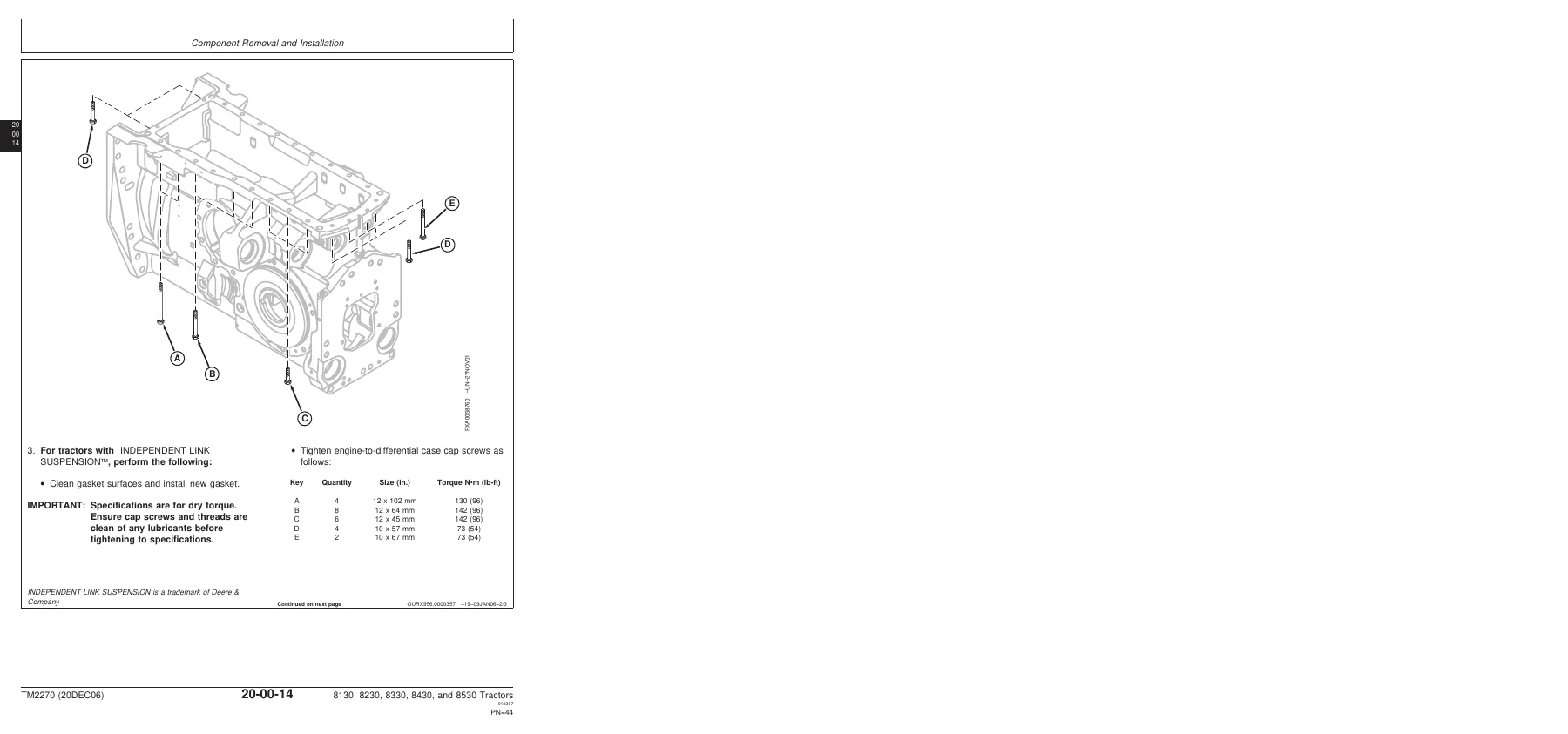
Critical fastener torque values are outlined with precision: 12 mm engine-to-front frame cap screws require 142 N·m (105 lb-ft), 10 mm cap screws require 73 N·m (54 lb-ft), and zinc-flake coated front frame-to-transmission cap screws must be tightened to 430 N·m (317 lb-ft). Drive shaft reassembly includes exact formula calculations when utilizing the JDG861 torque wrench adapter to guarantee accurate torque application to 126 N·m (92 lb-ft). In addition, full replacement instructions for the 38 kg (83 lb) flywheel dampener and inertia ring detail proper handling with the JDG879 lifting fixture and a 70 N·m (52 lb-ft) final torque specification.
Cooling Architecture & VARI-COOL Fan Drive Rebuild
Proper thermal management is critical on high-horsepower tractors. The TM2270 manual provides exhaustive service coverage for the advanced VARI-COOL variable-ratio belt drive system. Technicians can follow detailed photographic steps to relieve internal sheave hydraulic pressure via the bleed screw (torqued to 25 N·m / 221 lb-in), remove inner and outer sheaves, replace bearings, and rebuild the hydraulic piston assembly using JDG1860, JDG10018, and JDG10019 seal drivers. Outer drive sheave-to-drive cap screws must be secured to 375 N·m (276 lb-ft), while auxiliary drive belt tensioners are calibrated to 70 N·m (52 lb-ft).
IMAGES PREVIEW
Testing and diagnostic procedures for cooling circuits feature 80 kPa (0.8 bar / 12 psi) radiator pressure tests using the D05104ST tester and JDG839 adapter, alongside 60–80 kPa (0.6–0.8 bar / 9–11 psi) radiator cap opening thresholds. Clear schematics differentiate auxiliary belt routing configurations between machines equipped with and without trailer air brakes, ensuring proper tensioner alignment and belt longevity.
Advanced Electrical Harness Routing, Terminals & Sensor Calibration
Modern electrical repairs require detailed connector service knowledge. Section 40 provides in-depth repair instructions and tool listings for AMP, Deutsch, Cinch Flexbox, Metri-Pack, and Yazaki connectors, outlining wire extraction, seal seating, and terminal crimping using specialized ServiceGard tools. Tractor-wide wiring schematics illustrate exact routing for chassis, cab, console, transmission, and active suspension circuits.
Comprehensive sensor service procedures guide technicians through removal, reinstallation, and electrical calibration of critical electronic components: draft sensing sensors requiring a 4.8–5.2 V source voltage, 0.7–0.9 V fully extended, and 2.1–2.2 V adjustment range; kingpin-mounted wheel angle sensors torqued to 3 N·m (27 lb-in); and Independent Link Suspension cylinder position sensors utilizing CommandCenter service addresses (SFA 003, 004, and calibration address 020). Complete armrest control unit (ACU) service includes teardown and recalibration instructions for throttle friction discs, PST shift levers, AutoPowr speed controls, SCV paddles, and rear hitch controllers.
Why Technicians Rely on the TM2270 Technical Manual
Equipping your workshop with the John Deere 8130, 8230, 8330, 8430 and 8530 Tractors Service Repair Technical Manual (TM2270) ensures that every rebuild, teardown, and electrical overhaul is executed to factory specifications. Performing repairs without proper torque figures, seal drivers, or procedural sequences risks catastrophic mechanical failure, electrical shorts, or costly machine downtime during critical operating seasons. This manual provides direct dealer-level procedures, detailed cross-sectional views, and verified factory tolerances to keep your 8030 Series tractors working at maximum efficiency.
Upon purchase, this manual is delivered immediately as a fully accessible, digital PDF download. There are no shipping delays or damaged paper pages; save the manual to your smartphone, tablet, laptop, or shop computer for instant offline access in the field or print out dedicated chapter sections whenever needed.
Reviews
There are no reviews yet.