
Kalmar DCE 90-180 DCE 70-32E3-70-35E4 Forklift Maintenance Manual – UDCE02.03GB
Original price was: $39.95.$24.95Current price is: $24.95.
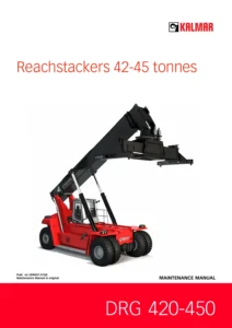
English maintenance manual for Kalmar DCE 90-180, DCE 70-32E3 and DCE 70-35E4 forklifts. Covers preventive maintenance, service schedule, engine, transmission, brakes, hydraulics, electrics, error codes and technical data. Publication UDCE02.03GB.
Description
The Kalmar DCE 90-180 DCE 70-32E3-70-35E4 forklift maintenance manual (publication UDCE02.03GB) is a complete service reference for keeping these heavy-duty Kalmar trucks running reliably. Written for Kalmar service technicians and authorized workshops, it covers preventive maintenance intervals, function descriptions, component locations and the first-line troubleshooting steps needed to identify and correct faults on DCE 90-180 and DCE 70-32E3/70-35E4 trucks running Volvo or Cummins engines and Dana transmissions. Every procedure and value in this manual is described as Kalmar expects it to be carried out in the field.
File Details
- Manual type: Maintenance Manual
- Brand: Kalmar
- Publication number: UDCE02.03GB
- Language: English
- Format: PDF
- Models covered: DCE 90-180, DCE 70-32E3, DCE 70-35E4
- Engine alternatives covered: Volvo TAD620VE (85 kW / 145 kW), Volvo TAD720VE (174 kW), Volvo TAD722VE (180 kW), Cummins QSB5.9 (138 kW)
- Transmission alternatives covered: Dana FT20000, HR28000, HR32000, TE13000, TE17000
- Cab alternatives covered: Spirit Delta, FlexGuard, FlexCab
- Approx. 600+ pages of procedures, diagrams and data
Chapters Covered
- A Foreword – purpose of the manual, reading instructions, function group structure, references, product alternatives and the machine card
- B Safety – service position, draining hydraulic pressure, working under the machine, lifting heavy components, vibrations, noise, solvents, fire and explosion risks, fluids under pressure, coolant, refrigerant, tensioned springs, tyres, lifting equipment and the environment
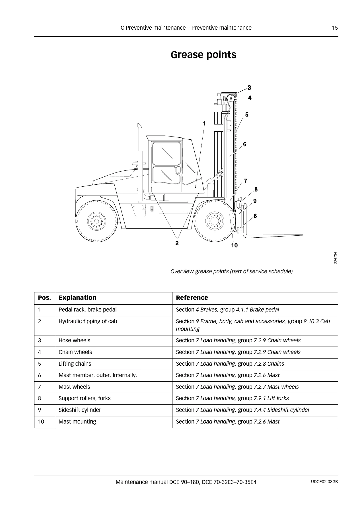
- C Preventive Maintenance – preventive maintenance general, 50h-check, check and service log, washing, service schedule and grease points
- 0 Complete Machine – machine description and general troubleshooting work instructions
- 1 Engine – fuel system, fuel tank, fuel filter, fuel pre-filter, particle filter, cylinder head, air cleaning system, exhaust system, intercooler, sensor boost pressure, cooling system, radiator, cooling fan, oil cooler, coolant, lubrication, oil filter, engine control system (ECU 794), start/stop
- 2 Transmission – transmission, lubrication, oil filter and transmission control system (ECU 793)
- 3 Driveline/Axle – propeller shaft and drive axle
- 4 Brakes – brake pedal, power-assisted brake system, distribution block, wheel brake and parking brake system
- 5 Steering – power-assisted steering system, link arm, wheel spindle and steering wheel angle sensor
- 6 Suspension – steering axle cradle, wheel hub and tyre and rim system
- 7 Load Handling – lift and lower, mast, mast wheels, chains, chain wheels, side shift, spreading, tilt, levelling, lift forks and side-lift attachment
- 8 Control System – controls and instrumentation, monitoring, ETC, automatic shifting, reverse lock-out, lever steering, mini-wheel, electro-hydraulic servo, scale, pre-selected lift height, vertical hold, Optimum speed/rev/drive, error codes and diagnostics for ECU 790, ECU 793, EDU 795 and ECU 796
- 9 Frame, Body, Cab and Accessories – controls and instrumentation, protection and emergency equipment, seats, HVAC, fresh air filter, condenser unit, control unit ECC, wiper/washer, lighting, communication systems, glass/windows/mirrors, cab structure and suspension, doors, cab mounting, cab tilt, cab interior, frame, body, counterweights and central lubrication
- 10 Common Hydraulics – security valves, tanks and accumulators, pumps (fixed and variable), hoses and pipes, main valve, measuring nipples, hydraulic oil cooler, breather filter, high-pressure filter and hydraulic oil
- 11 Common Electrics – electric protection, fuses, batteries, alternator, distribution of electricity, electrical distribution box, control units, start-up electrical system, cable harness and CAN-bus communication (redundant and drivetrain)
- D Error Codes – error code tables for Volvo TAD722VE, Cummins QSB5.9, Dana TE13000/TE17000 transmissions, and control system error codes from EDU 795, ECU 790 and ECU 796
- E Schematics – hydraulic diagrams A40750.0100 through A40750.1000 and electrical circuit diagrams A44067.0100 (with cross-reference sheets for ECU 790, ECU 793, ECU 796, ECU 794P and ECU 794C)
- F Technical Data – specifications for data and volumes, lift capacity and dimensions, oils and lubricants, ORFS tightening torques, general tightening torques, unit explanations and conversion tables
- G Terminology and Index – glossary of terms and abbreviations plus a full index
Read together, these chapters give a full maintenance and first-line troubleshooting picture of the Kalmar DCE 90-180 DCE 70-32E3-70-35E4 forklift. The manual is organised by function group rather than by repair order, so a technician can jump straight to the function involved (for example, group 4.3 Power-assisted brake system or group 7.2 Lifting/lowering), read the function description to understand what should happen, then follow the referenced component description and diagnostic test to trace the fault. Every system on the truck is described in the same way, which keeps the search path consistent regardless of whether the problem sits in the hydraulics, the electrics, the engine or the transmission.
What This Kalmar DCE Maintenance Manual Enables You To Do
With this manual on hand you can carry out the complete preventive maintenance schedule on your DCE 90-180 or DCE 70-32E3/70-35E4 truck without guessing at intervals or fluid grades. The service schedule splits actions clearly into 500 h, 1000 h and 2000 h services, and each action is referenced back to the exact function group where the work instruction lives. You get the 50 h check for new machines, the running 500 h service items (engine oil and filters, fuel filter, hydraulic high-pressure filter, cooling system, air filter, drive axle oil and grease points), and the 1000 h and 2000 h operations such as valve clearance, wheel bearings, king pin bearings and driveline checks.
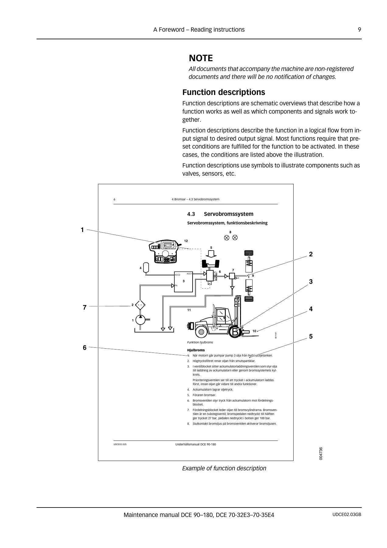
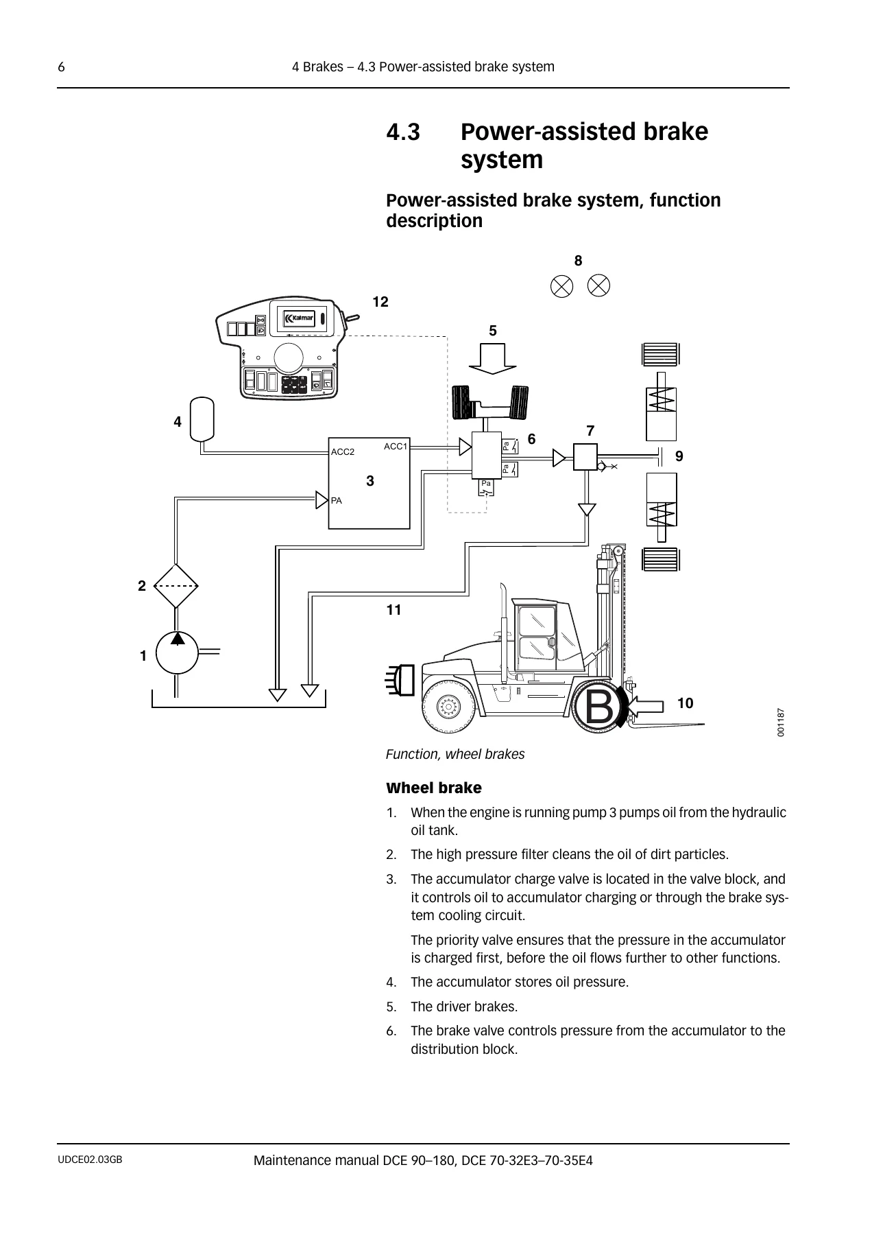
Beyond routine maintenance, the manual supports real repair and diagnostic work. The function descriptions in sections 0-12 show how each circuit is supposed to behave, including which signals are monitored, which conditions must be met before a function activates, and where pressure test points sit on the main valve and distribution block. The error code tables in section D are cross-referenced with the diagnostic menus in section 8, so a technician can read a code from the ECU, match it to the correct component, and use the wiring and hydraulic schematics to trace the fault to a specific pin, connector, valve or sensor.
Coverage Notes For DCE 90-180 And DCE 70-32E3/70-35E4 Owners
The manual covers several product alternatives side by side. Engine sections separately describe the Volvo TAD620VE, TAD720VE and TAD722VE families alongside the Cummins QSB5.9, and the transmission sections cover the Dana FT20000, HR28000, HR32000, TE13000 and TE17000 gearboxes. Where a procedure differs between a mechanically governed engine and an electronically controlled one, both variants are shown. The same pattern applies to cab alternatives (Spirit Delta, FlexGuard, FlexCab) and to options such as mini-wheel/lever steering, joystick, electrical servo load handling, electric scales, and the side-lift attachment.
Because the DCE 90-180 and DCE 70-32E3/70-35E4 are heavy trucks with many configurable features, the manual makes it clear when an instruction only applies to one alternative. Always match the truck’s actual specification (engine, transmission, cab, options) before following a procedure, and use the machine card as the reference when in doubt.
Technical Depth Worth Having On The Workshop Floor
Publication UDCE02.03GB goes well beyond a list of oil change intervals. It contains the fluid capacities and approved grades for the engine, transmission, drive axle and hydraulic system; the correct tightening torques for ORFS fittings, flange couplings, threaded ports and general fasteners; the accumulator precharge and maximum pressures; brake pedal pressures at half and full depression; tyre pressures for the 11.00-20 and 12.00-20 fitments; and the alternator ratings, battery specification and axle load data for each truck variant. This is the kind of data a workshop actually needs when a machine is up on axle stands.
Diagnostics are covered in the same detail. The CAN-bus sections explain how the control units communicate, what the termination resistance is meant to be, and how to interpret the messages and error code levels. The error code chapters list each code, the limitation it imposes on the machine, and the recommended action – whether that is checking a sensor, measuring a valve resistance, testing a cable, or verifying accumulator pressure. For electrical faults, cable harness troubleshooting procedures and PIN-out tables for each ECU are included, together with the connector numbering used throughout the electrical distribution box.
Who This Maintenance Manual Is Written For
This is Kalmar’s own maintenance manual, written for trained service technicians and workshop personnel who already understand the basics of hydraulic and electrical fault-finding. It is not a training course and it does not replace formal Kalmar service training. What it does do is give the reader the same reference material Kalmar uses, so the work can be carried out with the correct values, the correct sequence and the correct safety precautions. Every safety chapter is referenced back to the sections where the risk applies, and warnings are repeated where the risk is repeated.
Get The Kalmar DCE 90-180 DCE 70-32E3-70-35E4 Maintenance Manual Today
If you maintain, service or repair Kalmar DCE 90-180 or DCE 70-32E3/70-35E4 forklifts, having the UDCE02.03GB maintenance manual on hand turns guesswork into a defined procedure. You can plan the next service from the schedule, look up the correct oil, torque or pressure before you start a job, and trace an electrical or hydraulic fault through the function description, error code table and schematic. Correct procedures and correct specifications are what keep these trucks working and prevent damage from the wrong adjustment or the wrong fluid.
IMAGES PREVIEW
This is a digital PDF download. After payment you get instant access to the file, no shipping and no waiting. You can read it on a laptop, tablet or phone, print the pages you need for the workshop, and keep the whole manual in the cab or in the toolbox on a memory stick. Download once and use it for every service on the truck.
Reviews
There are no reviews yet.