
Kalmar DCE 90-180 Forklift Maintenance Manual 2006- PDF Download (DCE 70-32E3, DCE 70-35E4)
Original price was: $84.95.$49.95Current price is: $49.95.
400-page Kalmar DCE 90-180 forklift maintenance manual in PDF, covering DCE 70-32E3 and DCE 70-35E4 with Volvo, Caterpillar and Cummins engine alternatives. Instant download.
Description
File Details
- Manual type: Maintenance Manual
- Brand: Kalmar Industries
- Model coverage: DCE 90-180, DCE 70-32E3, DCE 70-35E4
- Engine alternatives: Volvo TAD650VE, TAD660VE, TAD750VE, TAD760VE; Caterpillar C6.6; Cummins QSB6.7
- Language: English
- Page count: 400 pages
- File format: PDF
- Publication number: UDCE08.03GB
- Edition: 2006-
Chapters Covered in This Kalmar DCE 90-180 Maintenance Manual
The manual is arranged in function groups that run from 0 through 11, with additional lettered sections for safety, preventive maintenance, technical data and terminology. The top-level chapters are:
- A Foreword
- B Safety
- C Preventive maintenance
- 0 Complete machine
- 1 Engine
- 2 Transmission
- 3 Driveline/axle
- 4 Brakes
- 5 Steering
- 6 Suspension
- 7 Load handling
- 8 Control system
- 9 Frame, body, cab and accessories
- 10 Common hydraulics
- 11 Common electrics
- D Error codes
- E Schematics
- F Technical data
- G Terminology and index
A Foreword, B Safety and C Preventive Maintenance
The opening foreword explains how the function-group structure works, how product alternatives and optional equipment are handled, and how the machine card is used to identify which drawings and options apply to a specific truck. The safety chapter is a full standalone section covering the service position, depressurising the hydraulic system through the accumulator drain valve, oil, fuel, coolant and refrigerant handling, working under a tipped cab or a raised machine, lifting heavy components, tyre and rim dangers, and the environmental rules for waste oil and refrigerant. Preventive maintenance then lays out the actual service schedule: the 50 h check for new machines, the 500 h / 1000 h / 2000 h intervals, the lubrication charts for both 500 h and 1000 h, and a crack-checking procedure that walks through cleaning, magnetic powder testing and penetrating-fluid confirmation. Check points for mast anchorage, tilt anchorage, drive axle anchorage, lifting forks, counterweight box, steering axle anchorage and the frame rear section are all illustrated.
0 Complete Machine
A compact but useful chapter describing the machine as a whole: the DCE 90-180 forklift with a lifting capacity of 9 to 18 tonnes depending on design, the six-cylinder four-stroke direct-injected diesel engine, the hydromechanical transmission with three forward and three reverse gears, the torque converter, the propeller-shaft and hub-reduction drive axle, the oil-immersed disc service brake, the disc parking brake acting on the drive axle input shaft, rear-wheel steering with a double-acting hydraulic cylinder, and the load-handling functions — lift and lower, tilt, side shift, spreading, levelling and load carrier.
1 Engine
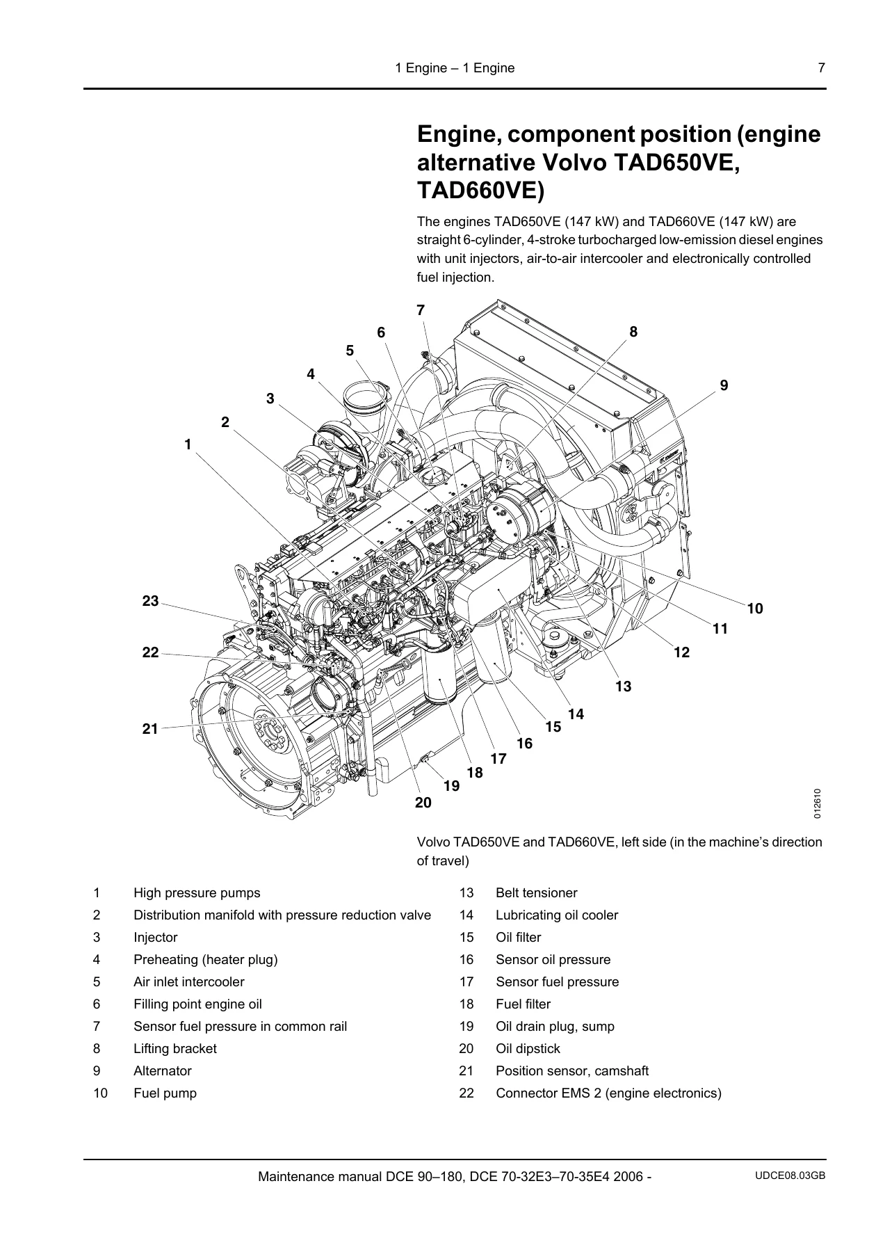
The engine chapter is the longest in the manual and is written around the engine families actually fitted to these trucks: Volvo TAD650VE, TAD660VE, TAD750VE and TAD760VE, Caterpillar C6.6, and Cummins QSB6.7. Each alternative has its own component-position illustrations, and the fuel system section covers the fuel tank, fuel filter and fuel pre-filter with separate bleeding and water-draining procedures per engine make. You get the particle filter service, valve-mechanism checking and adjustment (including Cummins lash specifications and the valve-clearance measurement sequence), air cleaning system and air filter changes, turbocharger inspection, exhaust system leak checks, intercooler and charge-air hose checks, the complete cooling system with coolant pump, radiator, cooling fan, drive belts and coolant mixing instructions, the lubrication system with engine oil and oil filter change, the engine control system, preheating, and start/stop.
2 Transmission
Covers the Dana TE 13000, Dana TE 17000 and ZF 3WG161 transmissions offered in these machines. The mechanical transmission description explains the constant-mesh design, hydraulically pressurised clutch discs, modulated forward/reverse engagement and the inching pedal. The lubrication system section covers oil level checking, transmission oil changing and oil filter replacement, with the different drain plug locations and torque figures for Dana and ZF. The transmission control system description covers the Limp-Home and Shut-Down modes, and there are step-by-step calibration procedures for both Dana and ZF transmissions, including heat mode, calibration codes and what each display message means.
3 Driveline/Axle
Propeller shaft checking — clean, check-tighten the mounting bolts to 98 Nm and check universal-joint clearance — plus the drive axle description with differential, drive shafts and hub reduction. Drive axle attachment is check-tightened to 650 Nm, and the chapter covers drive axle oil level checking and oil changing, including the hub reduction drain and level plugs, the differential carrier drain plug and the axle bleed valve.
4 Brakes
Three brake functions are documented: the power-assisted brake system with hydraulic oil tank, pump, filter, accumulator charging valve, accumulator, brake valve, pressure sensors, brake cylinder and the oil-cooled service brake units; the parking brake system with its own accumulator, control valve and solenoid valve; and the temperature control, cleaning and hydraulic oil circuit that cools the wheel brakes. Brake pedal checking and adjustment (1–1.5 mm clearance to the brake valve), brake pressure checking at the distribution block, and parking brake pad changing with the 0.5 ± 0.1 mm pad-to-disc clearance adjustment are all included.
5 Steering
Rear-wheel power-assisted steering with steering wheel, steering wheel shaft, steering valve, hydraulic oil pump, valve block with priority valve, steering cylinder, link arms and wheel spindles. The chapter also covers the reversible operator’s station variant where the steering angle is reversed by a directional control valve, and lever steering / mini-wheel steering with the steering wheel angle sensor. Link arm bearing checking and sensor checking are both covered.
6 Suspension
The steering axle cradle is mounted to the frame on two bushings; the chapter explains how to measure cradle play (max 3 mm), wheel spindle bearing clearance (max 0.25 mm) and wheel hub slack. The tyre and rim system section is effectively a sub-chapter of its own — rim inspection including lock ring and side ring condition, lock-ring wear measurement (max 0.5 mm), rim diameter measurement, crack checking by magnetic powder and penetrating fluid, tyre inflation, and complete wheel removal and installation procedures for both the drive axle and the steering axle, with the 650 Nm wheel nut torque.
7 Load Handling
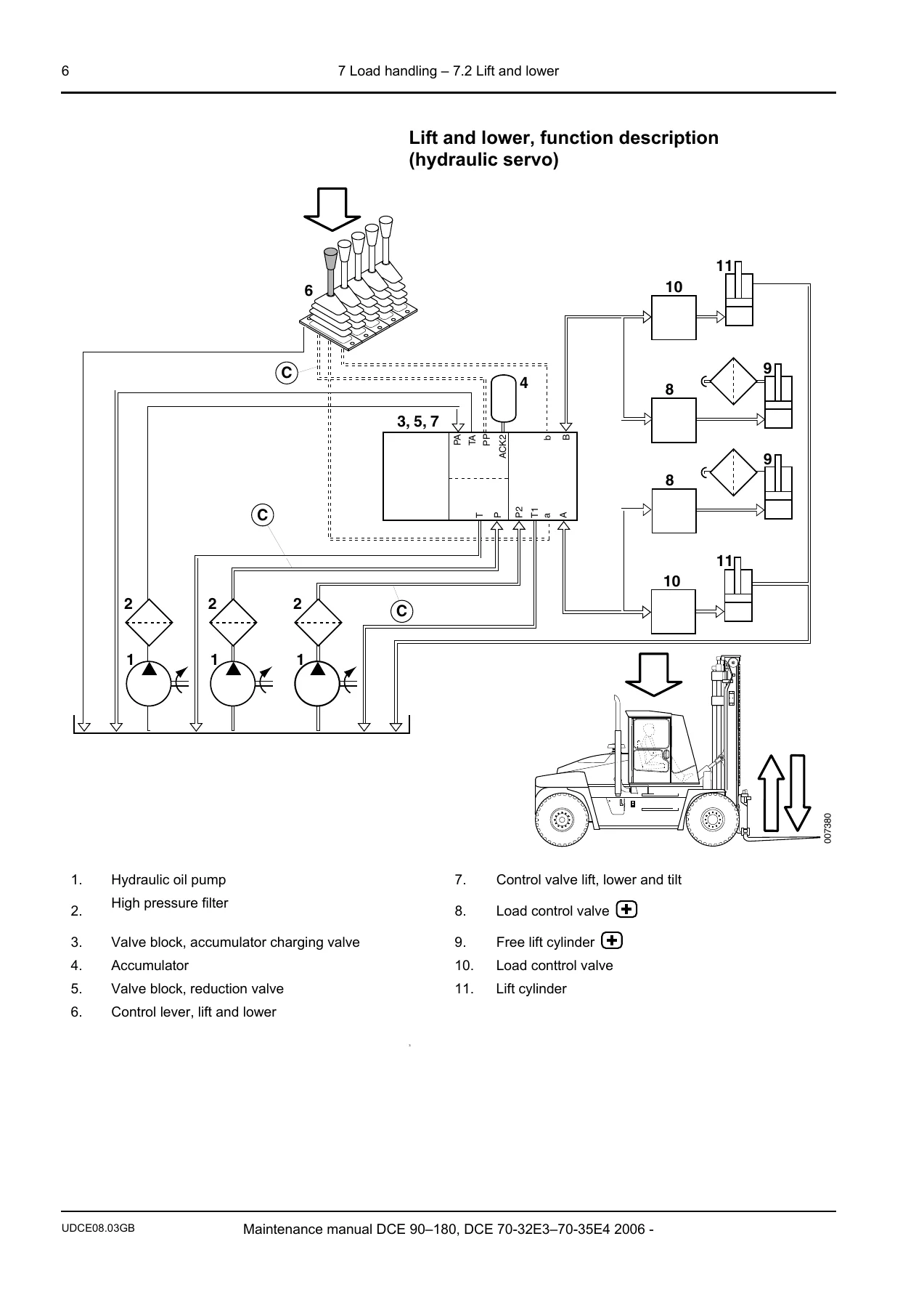
The other major chapter. Lift and lower, mast, chains, side shift, spreading, tilt, levelling, load carrier and lift forks are all documented, with both hydraulic-servo and electric-servo function descriptions for each function. The mast section covers mast anchorage play (max 2 mm), side support checking for top support, carriage and inner mast, and shim recommendations. Chains are checked for 3% elongation over 25 links and adjusted to 10–20 mm fork clearance. Lifting forks are checked for blade wear (max 10% at 150 mm from the heel) and cracking. Additional functions cover electric scale calibration, pre-selected lift height, vertical hold, Optimum speed, Optimum rev, Optimum drive and the side lift attachment with Twistlock and sensor inspection.
8 Control System
The machine’s electronic control and monitoring system is documented here: monitoring functions, speed limitation, service indicator reset, error code levels (STOP, WARNING, INFORMATION) and the diagnostic test menus for ECU 790, ECU 792, ECU 793 and ECU 796, plus the Last alarms history that stores the ten most recent error codes with fault counters and timestamps.
9 Frame, Body, Cab and Accessories
Cab overviews for Spirit Delta, FlexGuard and FlexCab, left and right instrument panels, steering wheel panel, arm rest, seats (Bege, Isringhausen 6500/6000, Grammer Actimo XXL, Grammer MSG 20, Grammer Maximo XXL), heating/ventilation/air conditioning with function description and component positions, fresh air and fine filter changing, condenser checking, wiper/washer, lighting, communication systems, glass/windows/mirrors, cab framework and mounting, cab tipping (manual and electric), door stop, cab interior, frame description and checking, body, counterweights, central lubrication (manual and automatic) and paint/coatings.
10 Common Hydraulics
Security valves and accumulator drain valve control, tanks and accumulators with accumulator checking (the brake must be applicable 8 times before a low brake pressure error code appears), fixed-displacement pumps (up to five pumps depending on options), hoses/pipes/valves, main valve with measuring nipples and pressure checking procedures for accumulator charging, steering, lift and tilt, side shift and spreading, and servo pressure. Temperature control, hydraulic oil cooler cleaning, breather filter replacement, high-pressure filter changing and hydraulic oil level checking, oil testing and oil changing are all covered.
11 Common Electrics
Electric protection with main fuses (4 × 25 A) and circuit fuses in the cab distribution box, battery description and checking (hydrometer values, electrolyte level), alternator, voltage feed (30-voltage and 15-voltage), electrical distribution box, control unit position and indication lamps, and CAN bus communication including the redundant CAN bus and the separate drivetrain CAN bus.
D Error Codes, E Schematics, F Technical Data and G Terminology
The error code and schematic sections point to the Workshop manual for detailed fault code listings and wiring/hydraulic diagrams. The technical data section is effectively a small reference manual of its own: power and torque figures for every engine alternative, alternator and battery ratings, particle filter data, transmission stall speeds, drive axle and propeller-shaft torque figures, brake pressures, accumulator precharge and maximum pressures, steering system data, tyre dimensions and pressures for every model, cab sound pressure levels, heat output, lighting bulb data, fuel tank capacities, coolant volumes, engine oil volumes, transmission oil volumes, drive axle oil volumes, refrigerant and washer fluid volumes, hydraulic system volumes, recommended oils and lubricants by ambient temperature, recommended tightening torques for metric and UNC bolts, ORFS coupling torques, air conditioning connection torques, and conversion tables for SI units, length, area, volume, weight and pressure. The terminology section closes the manual with a glossary of abbreviations (AC, ECC, ECU, KCS, SPN, FMI, Twistlocks, Optimum drive and so on) and a full index mapping every heading to its section and function group.
Why This Kalmar DCE 90-180 Maintenance Manual Belongs in Your Workshop
This is the document Kalmar wrote for the technicians who actually maintain these trucks. It gives you the service schedule, the lubrication charts, the pressure values, the torque figures, the calibration sequences and the component positions you need to keep a DCE 90-180, DCE 70-32E3 or DCE 70-35E4 running properly — whether you are servicing a Volvo-, Caterpillar- or Cummins-powered machine, doing a 500 h or 2000 h service, adjusting valve lash, changing a transmission oil filter, calibrating a Dana or ZF gearbox, bleeding a fuel system, or checking a mast anchorage for cracks.
IMAGES PREVIEW
Having the correct procedure and the correct specification in front of you is what separates a job done once from a job done twice. The manual gives you Kalmar’s own intervals, torque values and adjustment limits rather than a generic guess, and it shows you where every component sits on the machine before you start opening panels. Delivered as an instant PDF download, the file opens on any phone, tablet or computer, and every page can be printed for the workshop bench. No shipping, no waiting — the Kalmar DCE 90-180 maintenance manual is yours the moment checkout completes.
Reviews
There are no reviews yet.