
Kawasaki 115ZV Wheel Loader Shop Manual – Cummins QSK19-C Repair & Service PDF
Original price was: $83.95.$59.95Current price is: $59.95.
Complete 645-page Kawasaki 115ZV Wheel Loader Shop Manual with Cummins QSK19-C coverage. Full repair, hydraulic, electrical, transmission, brake and troubleshooting procedures. Instant PDF download.
Description
Kawasaki 115ZV Wheel Loader Shop Manual — Cummins QSK19-C
This is the complete Kawasaki 115ZV Wheel Loader Shop Manual, published under document number 93216-00226 (September 2014) and covering the Cummins QSK19-C diesel engine. All 645 pages of the original service manual are included in a single PDF. It is the manual Kawasaki service technicians use to diagnose, disassemble, measure, adjust, and reassemble the 115ZV — from the chassis and center pin through the torque converter, transmission, hydraulic system, brakes, and the full electrical system. The accompanying troubleshooting volume (93216-00230) is also included, along with the performance-check measurement section that gives the standard values against which a machine is judged.
File Details
- Manual type: Shop Manual (Service / Repair)
- Brand: Kawasaki / KCM Corporation
- Model: 115ZV Wheel Loader
- Engine: Cummins QSK19-C
- Document number: 93216-00226 (main shop manual); 93216-00230 (Troubleshooting / Measurement for Performance Check)
- Edition / date: September 2014 (main); June 2009 (Troubleshooting)
- Language: English (with multilingual explanation pages in French, German, Italian, Spanish and Portuguese for the electrical wiring diagram)
- Page count: 645 pages
- File format: PDF
Chapters Covered
- 00 General Information
- 01 Troubleshooting
- 03 Measurement for Performance Check
- 12 Function & Structure Chassis Group
- 13 Check & Adjustment Chassis Group
- 22 Function & Structure Power Group
- 23 Check & Adjustment Power Group
- 32 Function & Structure Torque Converter and Transmission Group
- 33 Check & Adjustment Torque Converter and Transmission Group
- 42 Function & Structure Hydraulic Group
- 43 Check & Adjustment Hydraulic Group
- 52 Function & Structure Brake Group
- 53 Check & Adjustment Brake Group
- 62 Function & Structure Electrical Group
- 63 Check & Adjustment Electrical Group
- 72 Function & Structure Operator Station Group
- 73 Check & Adjustment Operator Station Group
- 92 Cross-section drawing & Diagrams
General Information (00)
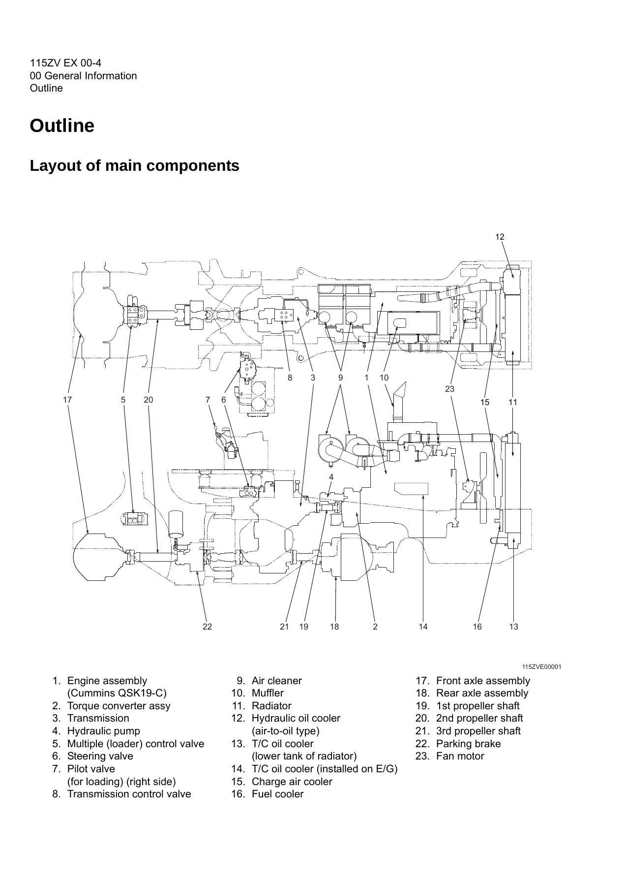
Layout of main components, the complete inspection and maintenance table with operating-hour intervals, recommended lubricants and refill capacities (engine 65 L, transmission 85 L, hydraulic tank 225 L, differential and planetary 180 L front / 180 L rear, fuel 670 L), coolant specification and antifreeze mixture ratios, a lubrication chart, weights of main components, bolt tightening torque tables in metric and unified thread, hose band tightening torques, and the liquid gasket and screw lock agent codes with application procedures. Welding repair precautions are also included.
Measurement for Performance Check (03)
Standard measurement values for both the Asia/Africa (S/N 0101~) and Europe (S/N 9001~) specifications. Engine speeds (low idle 775 ± 50, high idle 2,350 ± 50 for Asia/Africa; 2,250 ± 50 for Europe), stall speeds, multiple control valve relief speeds, clutch pressures, clutch time lags, cylinder drift limits, boom rising time, full steering time, relief valve setting pressures, fan motor line pressures, fan maximum revolutions, brake line pressures, accumulator charge time, number of brake pedal applications, and declutch engagement. Also contains the step-by-step measurement preparation and warm-up procedures.
Chassis Group (12, 13)
Front chassis and loading linkage, bucket and lever geometry, boom and bucket cylinder mounting, loading linkage pin diameters and bushing sizes, rear chassis with the fuel tank variants (S/N 0101~0211, 0212~), floor board viscous mounts, upper and lower center pin assemblies, dust seal orientation. Chapter 13 covers linkage pin adjustment, liner installation and clearances (1.0 mm for #1, 1.2 mm for #3~#7), center pin adjusting shims, bearing cover and bearing outer ring installation.
Power Group (22, 23)
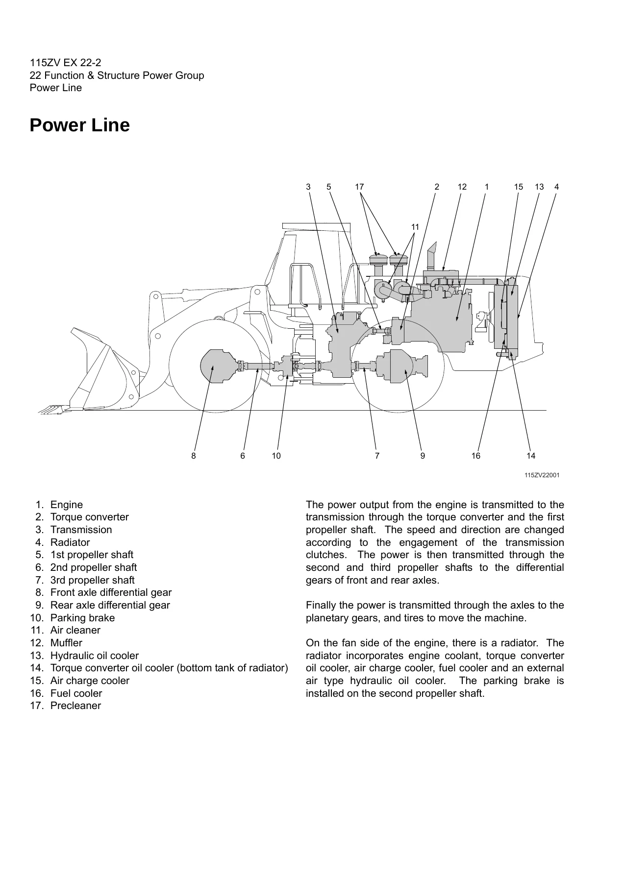
Power line layout, engine/transmission mounting with rubber cushions, radiator construction and mount, first/second/third propeller shaft assemblies, front and rear axle assemblies with exploded views of the wheel hub, planetary gears, service brake components, and axle support variants by serial number. Chapter 23 gives engine speed and oil pressure measurement, propeller shaft phase and alignment, tightening torques, axle nut tightening procedure with preload measurement, planetary gear oil drain and refill, differential gear adjustment including tooth contact patterns and preload adjustment with spacer selection.
Torque Converter and Transmission Group (32, 33)
Torque converter structure and power flow, gear pump specifications, transmission with six clutches (low range, high range, reverse, 1st, 2nd, 3rd speed), clutch combinations giving four forward and three reverse speeds, shift lever positions including automatic mode, planetary gear method, gear train and number of teeth. Clutch pack exploded views, power flow paths for forward 1st through 4th and reverse 1st through 3rd, hydraulic system and circuit diagrams, T/C and T/M oil circulation. The modulator valve unit, modulation mechanism, modulator valve 1 and 2 operation, pressure difference sensor, clutch solenoid valve construction, and the modulation chart with t1-t4 timings. Chapter 33 covers clutch oil pressure and time lag measurement.
Hydraulic Group (42, 43)
Flushing procedure, cautions on hydraulic parts replacement, hydraulic circuit symbols, hydraulic system operation for the loading, steering, fan motor and vibration damper (optional) systems, layout of hydraulic units, hydraulic tank specifications and breather valve operation, hydraulic pump construction and wear plate, hydraulic cylinder assemblies. Loading system with the pilot valve variants by serial number (S/N 0101~0140, 0141~0172, 0173~0176, 0177~), reducing valve, multiple control valve KML35A/2T103 with main relief, overload relief, make-up valve, bucket and boom spool operation, adapter (orifice), vibration damper, steering system with Orbitrol and steering valve KVS32-A4.0/21, stop valve, steering line filter, fan motor system with GM30C, GM30W and FM30 variants, thermo sensing valve, and emergency steering. Chapter 43 covers loading and steering circuit relief valve setting pressures, hydraulic cylinder natural drift, stop valve adjustment and fan motor revolution measurement.
Brake Group (52, 53)
Brake system outline (service, parking and auto brake), brake units layout, unloader valve by serial number, reducing valve, main brake manifold block, accumulator, in-line filter, brake valve for left and right pedal, stop lamp and declutch pressure switches, service brake construction with friction plate and steel plate details, service brake piston and pedal stroke adjusting mechanism, parking brake with spring chamber, parking brake manual release, brake circuit check valve, auto brake and shuttle valve. Chapter 53 covers brake circuit oil pressure, unloader valve setting pressure, reducing valve setting pressure, brake valve oil pressure, service brake performance and friction plate wear measurement, parking brake performance and clearance adjustment.
Electrical Group (62, 63)
How to use the electrical wiring diagram (with multilingual explanation pages), cable colour codes, circuit symbols, sensor mount, fuse box layout and capacities, engine start circuit with neutral starter, starter switch, battery relay, alternator I terminal wire, diode unit, neutral relay, magnet switch and voltage relay. Power generating/charging circuit, ECM (Engine Controller) with connection diagram, monitor lamp test, failure diagnosis, and Quantum fault code information. Transmission control circuit by serial number (S/N 0101~0153, 9001~ and S/N 0154~) with controller, connection diagrams, controller function, machine control unit (MCU), monitor circuit, instrument panel and switch, electrical detent circuit, diode checks, diagnostic system, and MODM. Chapter 63 covers cautions on electrical circuit checks, troubleshooting flowchart, transmission controller abnormal operation judgment, LED indicator tables, and individual circuit checks for shift lever input, inching, QUAD switch, machine speed sensor, clutch solenoid valve output, modulator valve output, neutral relay, parking brake, auto brake, gauge circuit, fuel level gauge, and bucket positioner.
Operator Station Group (72, 73)
Cabin with ROPS, glass part numbers and dimensions, front and rear wiper mounts and motor specifications, operator seat adjustment, steering and transmission shift lever with tilt case and column shaft, and the air conditioner section covering components, structure, cooling mechanism, cooling circuit, electrical circuit, function of components, refrigerant charging, and troubleshooting. Chapter 73 covers air conditioner lubricating oil quantity adjustment when components are replaced, air gap adjustment in the compressor magnetic clutch, and parts to be replaced periodically.
Cross-section drawing & Diagrams (92)
Axle assembly, torque converter and transmission, loading/steering hydraulic lines and circuits by serial range, brake circuit, full electrical wiring diagrams by serial number (including S/N 0101-0120, 0121-0124, 0125-0153, 0154-0222, 0223-, 9001-9010, 9011-), abbreviation charts, electrical connection diagrams, and the cabin air conditioner electrical circuit and equipment operation table.
Troubleshooting (01)
Quick troubleshooting tables organized by group. Torque converter and transmission: machine does not move in any position, does not move at a certain position, moves in neutral, large shock or time lag at starting/change, low power, oil overheating, reverse movement on slope with inching brake, automatic speed change failure, QUAD switch failure. Hydraulic: boom/bucket do not move, low power or slow, excessive cylinder drift, spongy operation, bucket positioner failure, steering failure, sway or shock during steering, abnormal noise. Brake: poor braking, dragging, buzzer on pedal, accumulator pressure problems, parking brake failure, auto brake failure. Electrical: instrument panel indication problems, controller breaker trips. Each entry lists symptom/check point, possible cause, and solution.
Why This Kawasaki 115ZV Shop Manual Matters
The 115ZV is a large, complex wheel loader. Its Cummins QSK19-C engine, six-clutch transmission, load-sensing hydraulic system, wet disc service brakes and electronically controlled auto brake are all interrelated — and a repair that ignores the manufacturer’s procedure can create a second failure before the first one is fixed. This manual provides the actual Kawasaki procedures: the torque values, the preload measurements, the relief pressure settings, the clutch pressure and time-lag windows, the serial-number-specific valve variants, and the fault codes the controller reports.
With it you can diagnose a no-move complaint through the transmission controller LEDs and the quick troubleshooting tables, pull the correct serial-number variant of the pilot valve or unloader valve, set the loading line main relief to 20.6 ± 0.5 MPa, adjust differential tooth contact, measure service brake friction plate wear with calipers, or recharge the air conditioner with the exact refrigerant quantity. The electrical wiring diagrams are included for every serial range, so the connector addresses and terminal numbering match the machine on the floor.
Delivery is instant. The PDF is delivered immediately after payment — no shipping, no waiting. Open it on a laptop, tablet or phone at the machine, or print the pages you need for the job. This Kawasaki 115ZV wheel loader shop manual is the same 645-page reference used in professional service work, and it stays with you for the life of the machine.
IMAGES PREVIEW
Reviews
There are no reviews yet.