Kawasaki Wheel Loader 95Z7 Service manual + Parts manual + Wiring diagrams + Troubleshooting manual – PDF DOWNLOAD
Original price was: $96.95.$39.95Current price is: $39.95.
Kawasaki Wheel Loader 95Z7 Service manual + Parts manual + Wiring diagrams + Troubleshooting manual
Description
Kawasaki Wheel Loader 95Z7 Service manual + Parts manual + Wiring diagrams + Troubleshooting manual
File Details:
Kawasaki Wheel Loader 95Z7 Service manual + Parts manual + Wiring diagrams + Troubleshooting manual
Language : English
Pages : 500+
Size : 172 MB
Downloadable : Yes
Format : PDF
KAWASAKI WHEEL LOADER 95Z7 SERVICE MANUAL + PARTS MANUAL + WIRING DIAGRAMS + TROUBLESHOOTING MANUAL – PDF DOWNLOAD:
Image Preview:
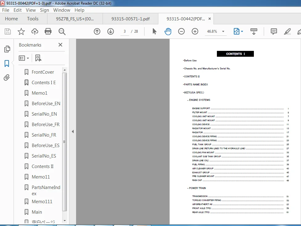
Table of Contents:
Kawasaki Wheel Loader 95Z7 Service manual + Parts manual + Wiring diagrams + Troubleshooting manual
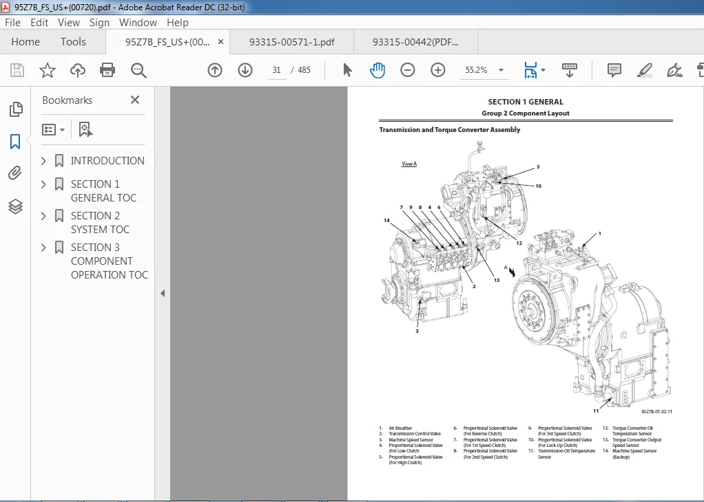
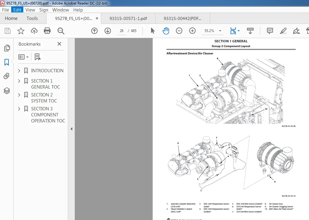
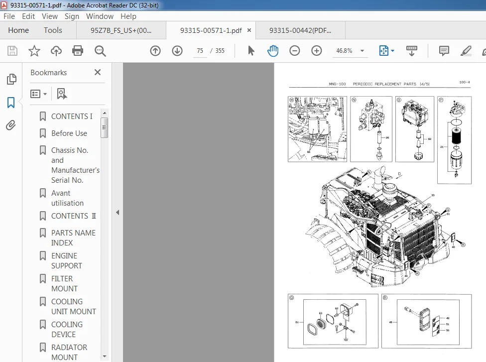
GENERAL...................................................................................  5
	1 Precautions for Disassembling and Assembling........................................  7
	2 Tightening.......................................................................... 13
	3 Painting............................................................................ 21
	4 Bleeding Air........................................................................ 27
		Hydraulic Oil Tank................................................................ 27
		Hydraulic System.................................................................. 28
		Fuel System....................................................................... 29
		Radiator.......................................................................... 31
		Brake (Axle)...................................................................... 32
		Parking Brake..................................................................... 33
	5 Pressure Release Procedure.......................................................... 35
		Front Attachment Hydraulic Circuit ............................................... 35
		Ride Control Accumulator (Option) ................................................ 36
		Parking Brake Accumulator ........................................................ 37
	6 Preparation......................................................................... 39
MAINTENANCE STANDARD...................................................................... 43
	1 Body................................................................................ 45
		Center Hinge...................................................................... 45
		Pilot Valve (Two Lever Type )..................................................... 47
	2 Front Attachment.................................................................... 49
		Pin and Bushing................................................................... 49
		Standard Dimensions for Lift Arm and Bucket....................................... 51
BODY...................................................................................... 53
	1 Cab................................................................................. 55
		Removal and Installation of Cab................................................... 55
	2 Counterweight....................................................................... 73
		Removal and Installation of Counterweight......................................... 73
	3 Center Hinge........................................................................ 77
		Removal and Installation of Center Hinge.......................................... 77
		Removal and Installation of the HydraulicHoses of Front Chassis Side.............. 85
	4 Engine.............................................................................. 89
		Removal and Installation of Engine................................................ 89
		Removal and Installation of Exterior Parts........................................117
		Removal and Installation of ROPS (Roll OverProtective Structure)..................126
		Removal and Installation of Deck and Step/Covers..................................128
		Removal and Installation of Air Cleaner...........................................131
	5 Radiator Assembly...................................................................135
		Replacement of Radiator and Cooling System........................................135
	6 Hydraulic Oil Tank..................................................................161
		Removal and Installation of Hydraulic Oil Tank....................................161
	7 Fuel Tank...........................................................................169
		Removal and Installation of Fuel Tank.............................................169
	8 Pump Device.........................................................................179
		Removal and Installation of Pump Device...........................................179
		Disassembly and Assembly of Pump Device...........................................185
		Disassembly of Main Pump..........................................................189
		Assembly of Main Pump.............................................................192
		Disassembly of Regulator..........................................................197
		Assembly of Regulator.............................................................201
		Removal and Installation of Accessory Pump........................................205
		Disassembly of Accessory Pump.....................................................207
		Assembly of Accessory Pump........................................................212
	9 Control Valve.......................................................................217
		Removal and Installation of Control Valve.........................................217
		Disassembly of Control Valve......................................................225
		Assembly of Control Valve.........................................................229
	10 Pilot Valve........................................................................231
		Removal and Installation of Pilot Valve...........................................231
		Removal and Installation of Pilot Valve (Two Lever Type ).........................237
		Disassembly of Pilot Valve........................................................243
		Assembly of Pilot Valve...........................................................246
		Disassembly of Pilot Valve (Two Lever Type).......................................251
		Assembly of Pilot Valve (Two Lever Type)..........................................257
	11 Unloader Valve.....................................................................265
		Removal and Installation of Unloader Valve (Brake Charge Valve)...................265
		Structure of Unloader Valve.......................................................269
		Disassembly of Unloader Valve.....................................................271
		Assembly of Unloader Valve........................................................272
		Removal and Installation of BrakeAccumulators.....................................275
	12 Combination Valve..................................................................279
		Removal and Installation of CombinationValve......................................279
		Structure and Tightening Torque of Combination Valve Components...................285
	14 Flow Regulator Valve...............................................................287
		Removal and Installation of Flow RegulatorValve...................................287
		Structure of Flow Regulator Valve.................................................291
	15 Cooling Fan System.................................................................293
		Removal and Installation of Fan Control Valve.....................................293
		Disassembly and Assembly of Fan Control Valve.....................................299
		Removal and Installation of Fan Motor.............................................305
		Structure of Fan Motor............................................................311
		Removal and Installation of Fan Pump..............................................313
		Disassembly and Assembly of Fan Pump..............................................314
	16 Exhaust Filter.....................................................................315
		Removal and Installation of Exhaust Filter........................................315
		Removal and Installation of Exhaust Filter Regeneration Control Solenoid Valve....319
		Disassembly and Assembly of Exhaust Filter Regeneration Control Solenoid Valve....321
	17 Ride Control Valve and Accumulator.................................................323
		Removal and Installation of Ride Control Valve and Accumulator....................323
		Disassembly of Ride Control Valve.................................................329
		Assembly of Ride Control Valve....................................................332
	18 Battery............................................................................335
		Removal of Battery Disconnect Switch..............................................335
		Installation of Battery Disconnect Switch.........................................336
		Structure of Battery Box Mount....................................................336
TRAVEL SYSTEM.............................................................................339
	1 Tire................................................................................341
		Removal and Installation of Front Tire............................................341
		Removal and Installation of Rear Tire.............................................343
	2 Drive Unit..........................................................................349
		Removal and Installation of Torque Converter......................................349
		Disassembly and Assembly of Torque Converter......................................353
		Disassembly and Assembly of Torque Converter Sub Assembly.........................362
		Removal and Installation of Transmission..........................................369
		Disassembly and Assembly of Transmission Assy.....................................379
		Disassembly of Transmission Assembly..............................................386
		Assembly of Transmission Assembly.................................................394
		Disassembly and Assembly of Clutch Assembly.......................................405
		Disassembly and Assembly of Low and Third Speed Clutch Assembly...................420
		Disassembly and Assembly of Second Speed Clutch Assembly..........................423
		Disassembly and Assembly of Reverse Clutch Assembly...............................426
		Disassembly and Assembly of First Clutch Assembly.................................429
		Disassembly and Assembly of High Clutch Spider Assembly...........................435
		Disassembly and Assembly of Gear Box Assembly.....................................441
		Disassembly and Assembly of Accumulator Assembly..................................445
		Removal and Installation of Transmission Control Valve............................449
		Disassembly and Assembly of Transmission Control Valve............................455
		Special Tools (For Transmission Assembly and Disassembly).........................459
		Drawings for Special Tools........................................................460
	3 Axle................................................................................465
		Removal and Installation of Front Axle............................................465
		Removal and Installation of Rear Axle.............................................471
		Disassembly of Axle...............................................................479
		Assembly of Axle..................................................................487
		Disassembly and Assembly of Spider Assembly.......................................498
		Disassembly and Assembly of Internal Gear Hub Assembly............................500
		Removal and Installation of Floating Seal.........................................504
		Removal and Installation of Differential..........................................507
		Disassembly and Assembly of Differential..........................................513
		Disassembly and Assembly of Parking Brake Piston Assembly.........................535
		Special Tools For Axle Assembly...................................................537
		Drawings for Special Tools........................................................538
	4 Propeller Shaft.....................................................................545
		Removal and Installation of Propeller Shaft.......................................545
	5 Brake Valve.........................................................................557
		Removal and Installation of Brake Valve...........................................557
		Disassembly and Assembly of Brake Valve Assembly..................................561
		Disassembly and Assembly of Brake Valve...........................................567
		Maintenance Standard..............................................................571
	6 Joystick Steering...................................................................573
		Removal and Installation of Joystick Steering Control Valve.......................573
		Disassembly and Assembly of Joystick Steering Control Valve.......................577
		Removal and Installation of Joystick Steering Pilot Valve.........................583
		Disassembly of Joystick Steering Pilot Valve......................................591
		Assembly of Joystick Steering Pilot Valve.........................................595
	7 Steering Valve......................................................................601
		Removal and Installation of Steering Valve........................................601
		Disassembly of Steering Valve.....................................................605
		Assembly of Steering Valve........................................................608
	8 Steering Cylinder...................................................................611
		Removal and Installation of Steering Cylinder.....................................611
		Disassembly of Steering Cylinder..................................................617
		Assembly of Steering Cylinder.....................................................620
		Removal and Installation of Steering Accumulator..................................625
		Tools for Steering Cylinder Disassembly and Assembly..............................627
	9 Secondary Steering Device...........................................................631
		Removal and Installation of Secondary Steering Pump (Option)......................631
	10 Reducing Valve.....................................................................639
		Removal and Installation of Reducing Valve........................................639
		Disassembly of Reducing Valve.....................................................641
		Assembly of Reducing Valve........................................................643
	11 Stop Valve.........................................................................645
		Removal and Installation of Stop Valve............................................645
		Disassembly of Stop Valve.........................................................649
		Assembly of Stop Valve............................................................650
	12 Main Pressure Block................................................................651
		Removal and Installation of Main Pressure Block...................................651
		Structure of Main Pressure Block..................................................653
	13 Priority Hammer Valve and Shuttle Valve............................................655
		Removal and Installation of Priority Hammer Valve and Shuttle Valve...............655
		Structure of Priority Hammer Valve and Shuttle Valve..............................659
	14 Check Valve........................................................................661
		Removal and Installation of Check Valve...........................................661
		Structure of Check Valve..........................................................663
FRONT ATTACHMENT..........................................................................665
	1 Front Attachment....................................................................667
		Removal and Installation of Front Attachment......................................667
		Removal and Installation of Lever (Bell Crank)....................................681
		Removal and Installation of Bucket................................................695
	2 Cylinder............................................................................703
		Removal and Installation of Lift Arm Cylinder.....................................703
		Removal and Installation of Bucket Cylinder.......................................711
		Disassembly of Lift Arm Cylinder..................................................723
		Assembly of Lift Arm Cylinder.....................................................727
		Disassembly of Bucket Cylinder....................................................733
		Assembly of Bucket Cylinder.......................................................737
		Tools for Cylinder Disassembly and Assembly.......................................743
Description:
Kawasaki Wheel Loader 95Z7 Service manual + Parts manual + Wiring diagrams + Troubleshooting manual
The service manual covers the following files:
93316-00272.pdf
93316-00282.pdf
93316-00282_se.pdf
93316-00380.pdf
E18P-01+115Z7+TM_RepairKit(TR).pdf
L13Z008E.pdf
115Z7(US-D&R)(93216-00590).pdf
115Z7(US-D&R)-Cover(KCM).pdf
115Z7(US-F&S)-Cover.pdf
115Z7(US-Trb)-Cover(KCM).pdf
115Z7_US_OMM+00606.pdf
115Z7+Diagrams.pdf
115Z7+F&S(US)(93216-00570).pdf
115Z7+PC+????-Cover.pdf
115Z7+Trbl(US)(93216-00580).pdf
93316-00271_USA(??).pdf
- Our shop manuals consist of the Technical Manual, the Workshop Manual and the Engine Manual.
Information included in the Technical Manual: Technical information needed for machine pre-delivery and delivery, operation and activation of all devices and systems, operational performance tests, and troubleshooting procedures. Each page has a number, located on the center lower part of the page, and each number contains the following information: Example: Technical Manual: T 1-3-5 T Technical Manual 1 Section Number 3 Group Number 5 Consecutive Page Number for Each Group - Information included in the Workshop Manual: Technical information needed for maintenance and repair of the machine, tools and devices needed for maintenance and repair, maintenance standards, and removal / installation and assembly / disassembly procedures. Information included in the Engine Manual: Technical information needed for machine pre-delivery and delivery and maintenance and repair of the machine, operation and activation of all devices and systems, troubleshooting and assembly / disassembly procedures
Please Note:
- This is the SAME exact manual used by your dealers to fix your vehicle.
- The same can be yours in the next 2-3 mins as you will be directed to the download page immediately after paying for the manual.
- Any queries / doubts regarding your purchase, please feel free to contact [email protected]


Iker Jeremy –