
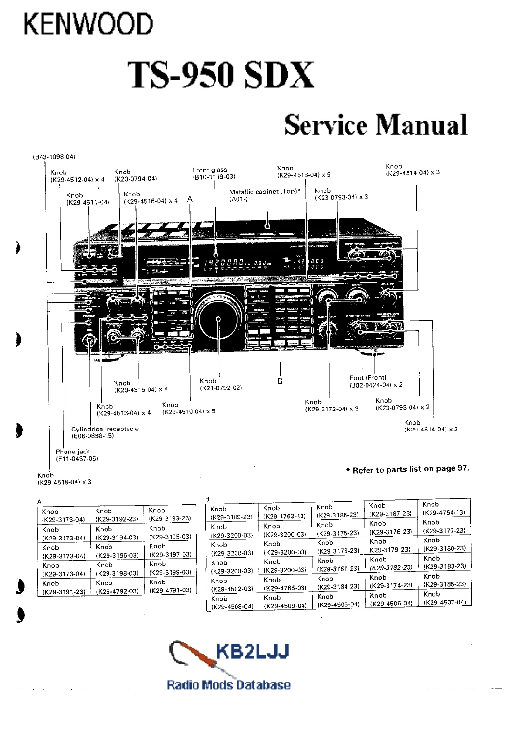
Kenwood TS-950SDX HF Transceiver Service Manual – Full Workshop PDF
Original price was: $39.95.$24.95Current price is: $24.95.
Complete Kenwood TS-950SDX HF transceiver service manual in PDF. Covers circuit description, PLL and DDS theory, receiver and transmitter signal paths, DSP unit, digital control, auto antenna tuner, alignment procedures, semiconductor data, parts lists, exploded views and full PC board/schematic diagrams.
Description
Kenwood TS-950SDX HF Transceiver Service Manual
This is the complete service manual for the Kenwood TS-950SDX HF transceiver, the SDX variant built on the TS-950SD platform with modified circuits and expanded functions. Inside you get the full technical documentation Kenwood produced for service technicians: circuit theory, block diagrams, alignment and adjustment routines, semiconductor data, parts listings, exploded views, board layouts and schematic diagrams covering every unit in the radio. If you maintain, repair, restore or align a TS-950SDX, this is the reference document that tells you how the radio is actually put together and how each stage is supposed to behave.
File Details
- Manual type: Service Manual
- Brand: Kenwood
- Model: TS-950SDX HF Transceiver
- Language: English
- Page count: 349 pages
- File format: PDF
Chapters Covered
- Circuit Description
- Units for Destination
- Accessories
- Overview
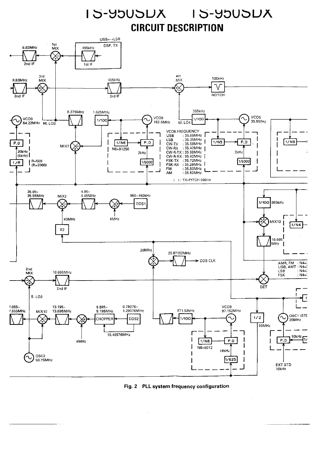
- Frequency Configuration
- PLL Circuit
- Receiver Circuit Configuration
- Transmitter Circuit Configuration
- AT Unit
- Standby Control and Timing
- Voice Memory Operation
- Final Unit
- DSP Unit
- Digital Control Unit
- AVR Unit
- Description of Components
- Semiconductor Data
- Parts List
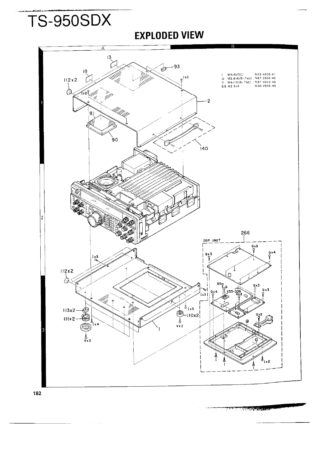
- Exploded View
- Packing
- Adjustment
- Terminal Function
- PC Board Views / Circuit Diagrams
- AVR Unit, RF Unit, Final Unit, Digital Unit, IF Unit, AF Unit, PLL Unit, CAR Unit
- Filter Unit, AT Unit, Control Unit, DSP Unit, Display Unit, Signal Unit
- Switch Unit (A), Switch Unit (B)
- Schematic Diagram, VCO2, VCO, VOX, FM MIC, NB2, VCO1, LPF, MKR, CWT, MAP, TRX, ALC, MIC AMP
- Block Diagram, Level Diagram
- DRU-2, RM-1, SP-950, VS-2, Option Filter, Specifications
Read as a whole, this Kenwood TS-950SDX service manual gives a technician the complete signal chain from antenna to audio output and back again. The frequency configuration chapter explains the quadruple-conversion receive path used in SSB, CW, AM and FSK, the triple-conversion FM path, and the double-conversion transmit path in FM mode, with the 100 kHz IF routed to the DSP in receive and microphone or key input routed to the DSP unit in transmit. The PLL chapter works through the reference signal generation circuit, DDS clock generation, main LO1 through LO4, sub LO1 and LO2, sub CAR and main CAR loops, plus the DDS IC registers, chopper circuit and SIN ROM conversion. The DSP chapter covers PSN modulation and detection, the sampling frequencies used, the analog and digital unit split, high-pass filter, limiting amplifier, AAF and SMF filters, sample-and-hold, A/D and D/A conversion and the 455 kHz conversion mixer. The digital control unit chapter documents the CPU, ROM, RAM, I/O port expanders, encoder circuit, system reset and RAM backup, address decoding, analog inputs, display drive, PLL and DDS data, key scan matrix, bandscope signal, electronic keyer, AT control and IF filter switching.
Coverage of Receiver, Transmitter and Control Systems
The receiver circuit configuration chapter traces the RF input through the attenuator, low-pass filter, 15-band BPF selected by RX BPF data, RF AGC, RF amplifier, and the split into main and sub channels. It documents the first main IF at 73.05 MHz, the MCF filtering, second mixer down to 8.83 MHz, the noise blanker gate, the second IF filter bank with LC filters, 6 kHz MCF, 2.7 kHz MCF and 500 Hz crystal filter, the third mixer to 455 kHz, the fourth receive mixer to 100 kHz, and the DSP hand-off. FM mode is handled separately through the 455 kHz IF buffer, ceramic filters, limiter amplifier and ceramic discriminator, with the FM AGC amplifier, squelch chain and de-emphasis circuit explained. The sub receiver path from 40.055 MHz first sub IF through the 10.695 MHz second IF, product detector and SAF output is also covered, along with the filter ratings tables for every MCF, ceramic and crystal filter used in the radio.
On the transmit side, the manual walks through the microphone input, MIC AMP module, SSB/AM MIC path versus FM/VOX path, the DSP MIC signal routing, the 455 kHz modulated IF returning to the signal unit, the speech processor with its clipper and level control, the 8.83 MHz IF chain with ceramic and crystal filters, the second local mixing to 73.05 MHz, the RF unit LC bandpass filters, first local mixing to the transmit frequency, the three-way split into low-pass, 7.5 to 14.5 MHz and 14.5 to 30 MHz bandpass sections, the drive output, and the final unit with its pre-drive, drive and final stages. The final unit chapter explains the change to a power MOS FET (MRF150MP) output device, the modified bias circuit with separate bias adjustment per FET, negative feedback for gain control, teflon coaxial cable in the output transformer, and temperature compensation diodes. The ALC circuit, power control circuit, SWR protection, IC protection, temperature protection and safety discharge cooling circuit are all documented with component references.
Alignment, Adjustment and Test Procedures
The adjustment chapter is one of the most practical parts of this Kenwood TS-950SDX service manual. It lists required test equipment including DC voltmeter, DC ammeter, RF VTVM, AF voltmeter, AF generator, dummy loads, oscilloscope, sweep generator, standard signal generator, frequency counter, noise generator, linear detector, power meter, spectrum analyzer, directional coupler, monitor receiver, microphone and tracking generator. It then gives the preparation settings, front panel and rear panel layouts, the procedure for entering and exiting adjustment mode, the memory channel frequency and mode table used as adjustment reference points, and a full step-by-step alignment sequence covering AGC, mixer balance, BPF, MCF, IF amplifier, IF output, notch filter, S-meter, SSB and CW filter alignment, VBT, slope tune, AGC switch settings, reference oscillator, scope S-meter, external standard voltage, and VCO adjustments for VCO5, VCO4, VCO9, VCO6, VCO8, VCO7, VCO0 and VCO1 with target voltages and reference waveform levels for each.
Parts Data, Exploded Views and Board Layouts
Because the manual includes the complete parts list with reference numbers, address codes, Kenwood part numbers and descriptions, it doubles as a component identification resource when a part needs to be matched, cross-referenced or replaced. Exploded view drawings show how the chassis, heatsink, fan, boards, connectors, knobs, feet and display assembly go together, and the packing section documents the original carton, protection bags, packing fixtures and accessory items. The PC board views and circuit diagrams section then provides board-level layouts and schematics for the AVR, RF, final, digital, IF, AF, PLL, CAR, filter, AT, control, DSP, display, signal and switch units, plus the main schematic diagram and the individual module schematics for VCO2, VCO, VOX, FM MIC, NB2, VCO1, LPF, MKR, CWT, MAP, TRX, ALC and MIC AMP. Block and level diagrams round out the signal-flow documentation. Option sections cover the DRU-2 digital recording unit, RM-1 remote function keyboard, SP-950 external speaker and VS-2 voice synthesizer.
What This Manual Lets You Do
With this Kenwood TS-950SDX HF transceiver service manual on hand you can trace a dead receiver or weak transmit path stage by stage using the block diagrams and the circuit descriptions, align the PLL and CAR loops to the specified voltages and reference frequencies, set VCO levels for each band segment, adjust the IF filter bank and notch circuit, set ALC and power control for correct output, diagnose protection circuit trips, identify a failed semiconductor from the data section, and order the correct replacement part from the parts list. Restoration work becomes far more predictable when you can compare measured behaviour against the documented operating points instead of guessing at circuit function.
Why a Proper Service Manual Matters on the TS-950SDX
The TS-950SDX is a complex radio: multiple PLL loops, DDS-based first local oscillators, a DSP unit handling modulation and detection, a digital control section with EEPROM-stored adjustment data, and an automatic antenna tuner with motor-driven variable capacitors and preset memory. Working on it without documentation risks misaligning loops, disturbing stored calibration data, or damaging the final FET through incorrect bias setup. The procedures in this manual are written around the actual measurement points and adjustment components in this chassis, which is what makes the difference between a repair that holds and one that drifts back into fault.
IMAGES PREVIEW
Instant PDF Delivery
This Kenwood TS-950SDX service manual is delivered as a PDF download immediately after checkout. There is no shipping, no waiting for a parcel and no physical book to lose. Open it on a laptop, tablet or phone in the workshop, or print the pages you need for the bench and keep the rest on file. Whether you are aligning a single VCO, tracing an IF fault, rebuilding the final unit or restoring a complete TS-950SDX, having the full manual within reach means you can work from the documented procedure rather than from memory.

Reviews
There are no reviews yet.