★ TRUSTED BY 321,897+ PROFESSIONALS WORLDWIDE
🏒
Trusted Business
Verified & Licensed
πŸ›‘οΈ
Virus Free Files
100% Safe Downloads
πŸ”’
Secure Payment
SSL Protected
⚑
Instant Delivery
Available Immediately
Sale!

Kobelco SK200-10 SK210LC-10 Hydraulic Excavator Shop Manual PDF Download

Original price was: $39.95.Current price is: $24.95.

Complete 1312-page Kobelco SK200-10 and SK210LC-10 hydraulic excavator shop manual covering specifications, maintenance, hydraulic and electrical systems, disassembly, troubleshooting, mechatro controller, attachments, travel system, upper slewing structure, and the HINO J05E-TG engine.

⚑
Instant PDF Download
Available immediately
πŸ’Ύ
Save to Your Device
Download & keep forever
πŸ›‘οΈ
Antivirus Scanned
100% virus-free
🌍
Trusted Worldwide
175,000+ customers

Description

Kobelco SK200-10 SK210LC-10 Shop Manual

This Kobelco SK200-10 SK210LC-10 Shop Manual is the complete technical service and repair guide for the Kobelco SK200-10 and SK210LC-10 hydraulic excavators. Published under document number S5YN0051E01, this 1312-page manual delivers the specifications, procedures, and service data needed to maintain, diagnose, disassemble, repair, and reassemble every major system on these machines. Whether you are servicing the hydraulic pump, troubleshooting an error code, overhauling the HINO J05E-TG engine, or rebuilding the travel motor, this shop manual provides the step-by-step guidance and factory reference values required to complete the job correctly.

File Details

  • Manual Type: Shop Manual / Service Repair Manual
  • Brand: Kobelco
  • Models Covered: SK200-10, SK210LC-10
  • Engine Model: HINO J05E-TG
  • Document Number: S5YN0051E01
  • Publication Date: 2016
  • Language: English
  • Page Count: 1312
  • File Format: PDF

Chapters Covered

  • 1. Outline β€” Copyright, General Precautions for Repairs, Preparation Before Disassembling, Safety When Disassembling and Assembling, Disassembling and Assembling Hydraulic Equipment, Electrical Equipment, Hydraulic Parts, Weld Repair, Environmental Issues, International Unit System
  • 2. Specifications β€” Basic Components of the Machine, General Dimensions (SK200-10 and SK210LC-10), Weight of Components, Specifications for Transportation, General Specifications, Type of Crawler, Type of Bucket, Combinations of Attachment, Engine Specification
  • 3. Attachment Dimensions β€” Boom Dimensional Drawing, Boom Maintenance Standard, Arm Dimensional Drawing, Arm Maintenance Standard, Bucket Dimensional Drawing, Bucket Dimensional Table, Lug Section Dimensional Drawing, Boss Section Dimensional Drawing
  • 4. Tools β€” Tightening Torques for Capscrews and Nuts, Screw Size and Nominal Size of Tool, Tightening Torque for Hose and Fitting, Tightening Torques for Nuts and Sleeves, Plug, Special Spanner for Tube, Special Tools, Application of Screw Locking Compound and Sealing Compound, Suction Stopper, Counter Weight Lifting Jig, Engine Mounting Pedestal, Track Spring Set Jig
  • 5. Standard Maintenance Time Table β€” Preface, Standard Working Time Table for the Maintenance of Excavator (Attachment, Cab & Guard, Swing Frame, Travel System, Electric Equipment)
  • 6. Maintenance Standard and Test Procedure β€” How to Use Maintenance Standards and Precautions, Performance Inspection Standard Table, Measurement of Engine Speed, Measurement of Hydraulic Pressure, Measuring Travel Performances, Measuring Swing Performances, Measuring Attachment Operating Performances, Measuring Performances of Swing Bearing, Mechatronic Controller
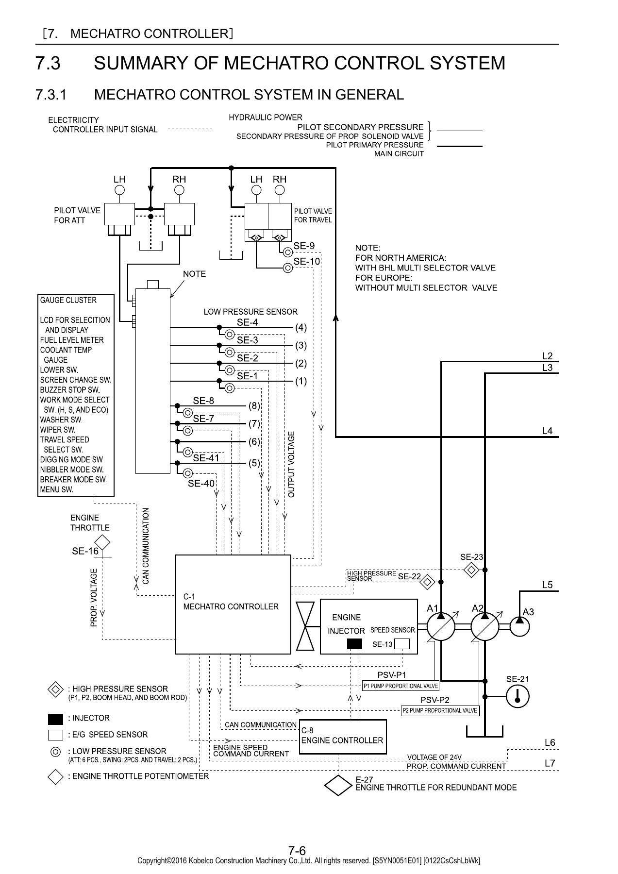
  • 7. Mechatronic Controller β€” Summary of Mechatronic Control System, Unload Valve Control, Positive Control and P-Q Control, Boom Up Conflux Control, Control of Arm-In Recirculation and Conflux, Arm-In Anti-Cavitation Control, Arm-Out Conflux Control, Boom Down and Arm-Out Control, Bucket Digging and Anti-Cavitation Control, Swing Priority Control, Travel Straight Control, Pressure Release Control, Warning of Return Filter Clogging, Mechatronic Controller multi-display, Self Diagnosis Display Function, Service Diagnosis Display Function, Trouble History Display Function, Various Adjustment Functions
  • 8. Hydraulic System β€” Hydraulic Circuits and Components, Neutral Circuit, Travel Circuit, Bucket Circuit, Boom Circuit, Swing Circuit, Arm Circuit, Combined Circuit, Pressure Draining
  • 9. Electrical System β€” Electrical Equipment List, Electrical Diagram, Harness (list, instrument panel, controller & relay box, operators controls, switch installation, upper harness, cab harness, boom harness, light installation)
  • 10. Components System β€” Hydraulic Pump (Regulator), Control Valve (construction, operation), Pilot Valve (ATT), Pilot Valve (Travel), Swing Motor Unit (construction, operation), Travel Motor Unit (construction, operation), Swivel Joint, Control Valve (N&B), Pilot Valve (N&B), Cylinder (construction), Electrical Equipment
  • 11. Air-Conditioner System β€” Basic System of Air Conditioner, Air Conditioner Component and Construction, Air Conditioner Piping, Air Conditioner Function, Air Conditioner Disassembly and Assembly, Charging Refrigerant, Air Conditioner Electric Circuit, Air Conditioner Troubleshooting, Panel Display for Self Diagnosis
  • 12. Disassembling and Assembling β€” Explaining Chapter of Whole Disassembly & Assembly
  • 13. Attachments β€” Removing and Installing Attachment (bucket, arm, boom), Disassembling and Assembling Cylinder
  • 14. Upper Slewing Structure β€” Removing and Installing Assembly (operator’s seat, cab, battery, guard, under cover, fuel tank, hydraulic oil tank, hydraulic pump, air cleaner, muffler, counterweight, radiator and oil cooler, engine, console cover, control valve, pilot valve, swing motor unit, swivel joint, upper frame), Disassembling and Assembling Component (hydraulic pump and regulator, control valve, pilot valve, swing motor unit, swivel joint)
  • 15. Travel System β€” Removing and Installing Assembly (crawler, upper roller, lower roller, front idler, sprocket, travel motor, swing bearing), Removal and Installation of Travel Motor Unit, Travel Motor Disassembly and Assembly, Maintenance Standard, Troubleshooting
  • 16. Trouble Shooting (By Error Codes) β€” Judgment of Actual Thing at Site, Classification of Failure and Troubleshooting, The Blown Fuse of Mechatronic Controller, Troubleshooting by Error Code (complete error code list and diagnostic procedures)
  • 17. Troubleshooting (By Trouble) β€” Hydraulic System Troubleshooting (all controls, engine down, lever neutral, poor fine operability, boom up/down, arm in/out, bucket, swing, travel), Electric Systems (wiring checking procedure, trouble), Failure Diagnosis Table for Engine Related Parts
  • 18. Engine β€” General (warnings, precautions, tightening of engine/chassis bolts and nuts, flare nuts and hoses, taper thread sealant, joints and gaskets, liquid gasket, failure diagnosis), Standard Value (engine body, fuel system, electrical, intake, engine mechanical, exhaust, cooling, lubrication, starting and charging, turbocharger), Parts to be Prepared, Engine Mounting/Dismounting, Fuel System (supply pump, injector, common rail), Electrical, Intake, Engine Mechanical (cylinder head, cylinder block, timing gear cover, flywheel housing, main moving parts, camshaft, idle gear, valve system), Exhaust, Cooling, Lubrication, Starting and Charging (starter, alternator), Turbocharger, Failure Diagnosis for Each Engine Status, Engine Diagnosis Code

This shop manual goes well beyond a simple repair guide. It is a complete technical reference that combines the machine specifications, component weights and dimensions, step-by-step disassembly and assembly procedures, hydraulic and electrical circuit diagrams, maintenance standards, troubleshooting flowcharts, and engine service data into a single organized document. Every chapter is written to be used directly at the machine, with exploded views, sectional drawings, tightening torques, service limits, and measurement procedures called out at the point of use.

Complete PDF Bookmark Tree

Complete Bookmarks

The complete bookmarks in the β€œKobelco SK200-10 SK210LC-10 Hydraulic Excavator Shop Manual PDF Download” are as follows:

S5YN0051E01(CMS)_A4-1p. 1
Cover_S5YN0051E01(forCMS)p. 1
S5YN0051E01(CMS)p. 7
1.1ABOUT THE COPYRIGHT OF THIS SHOP MANUALp. 9
1.2GENERAL PRECAUTIONS FOR MAKING REPAIRSp. 10
1.2.1PREPARATION BEFORE DISASSEMBLINGp. 10
1.2.2SAFETY WHEN DISASSEMBLING AND ASSEMBLINGp. 10
1.2.3DISASSEMBLING AND ASSEMBLING HYDRAULIC EQUIPMENTp. 11
1.2.4ELECTRICAL EQUIPMENTp. 13
1.2.5HYDRAULIC PARTSp. 13
1.2.6WELD REPAIRp. 14
1.2.7ENVIRONMENTAL ISSUESp. 14
1.3INTERNATIONAL UNIT SYSTEMp. 15
2.1ABOUT THE COPYRIGHT OF THIS SHOP MANUALp. 19
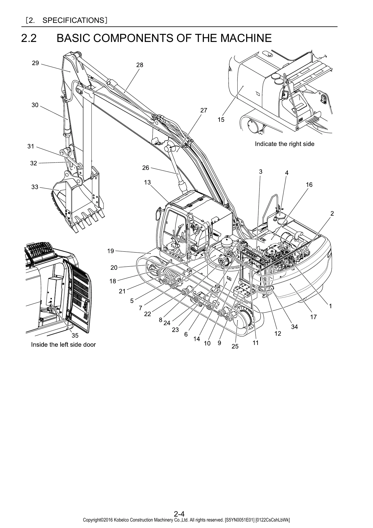
2.2BASIC COMPONENTS OF THE MACHINEp. 20
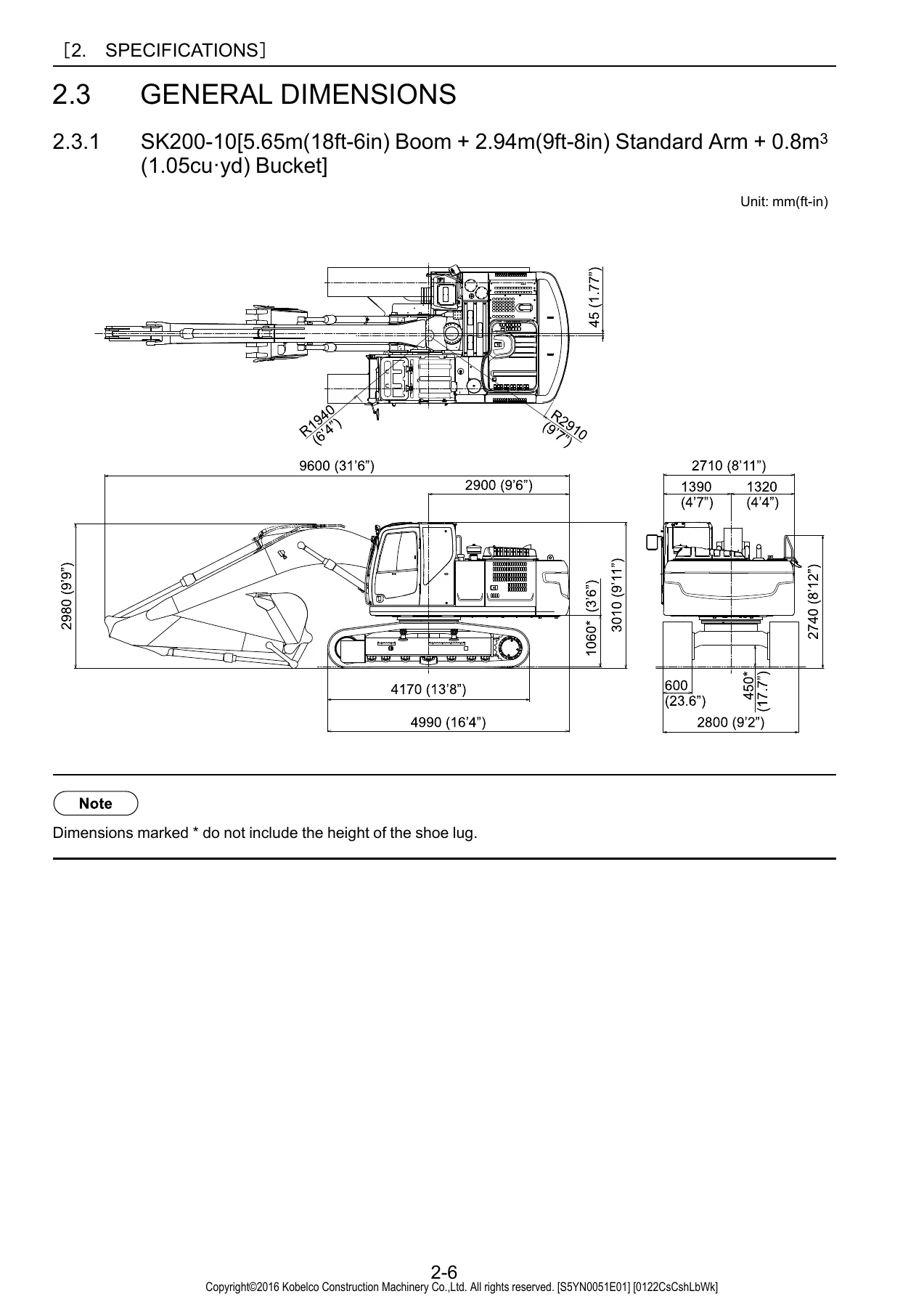
2.3GENERAL DIMENSIONSp. 22
2.3.1SK200-10[5.65m(18ft-6in) Boom + 2.94m(9ft-8in) Standard Arm + 0.8m3(1.05cuΒ·yd) Bucket]p. 22
2.3.2SK210LC-10[5.65m(18ft-6in) Boom + 2.94m(9ft-8in) Standard Arm + 0.8m3(1.05cuΒ·yd) Bucket]p. 23
2.4WEIGHT OF COMPONENTSp. 24
2.5SPECIFICATIONS FOR TRANSPORTATIONp. 25
2.5.1DIMENSIONS AND WEIGHT OF ATTACHMENT/EQUIPMENTp. 25
2.6GENERAL SPECIFICATIONSp. 27
2.6.1SPEED AND CLIMBING CAPABILITYp. 27
2.6.2ENGINEp. 27
2.6.3HYDRAULIC COMPONENTSp. 27
2.6.4WEIGHTp. 27
2.7TYPE OF CRAWLERp. 28
2.7.1SK200-10 TYPE OF SHOEp. 28
2.7.2SK210LC-10 TYPE OF SHOEp. 28
2.8TYPE OF BUCKETp. 29
2.9COMBINATIONS OF ATTACHMENTp. 30
2.10ENGINE SPECIFICATIONp. 31
2.10.1SPECIFICATIONSp. 31
3.1ABOUT THE COPYRIGHT OF THIS SHOP MANUALp. 35
3.2BOOMp. 36
3.2.1BOOM DIMENSIONAL DRAWINGp. 36
3.2.2BOOM MAINTENANCE STANDARDp. 37
3.3ARMp. 40
3.3.1ARM DIMENSIONAL DRAWINGp. 40
3.3.2ARM MAINTENANCE STANDARDp. 42
3.4BUCKETp. 45
3.4.1BUCKET DIMENSIONAL DRAWINGp. 45
3.4.2BUCKET DIMENSIONAL TABLEp. 45
3.4.3LUG SECTION DIMENSIONAL DRAWINGp. 46
3.4.4BOSS SECTION DIMENSIONAL DRAWINGp. 47
4.1ABOUT THE COPYRIGHT OF THIS SHOP MANUALp. 51
4.2TIGHTENING TORQUES FOR CAPSCREWS AND NUTSp. 52
4.3SCREW SIZE AND NOMINAL SIZE OF TOOLp. 54
4.3.1CAPSCREW (HEX HEAD BOLT)p. 54
4.3.2CAPSCREW (HEX HEAD SOCKET BOLT)p. 54
4.3.3SET SCREW (HEX HEAD SOCKET SET SCREW)p. 54
4.4TIGHTENING TORQUE FOR HOSE AND FITTINGp. 55
4.4.1JOINT (O-RING TYPE)p. 55
4.4.2HYDRAULIC HOSE (30 DEG. FLARE TYPE)p. 55
4.4.3ORS FITTNIGp. 55
4.4.4SPLIT FLANGEp. 55
4.5TIGHTENING TORQUES FOR NUTS AND SLEEVESp. 56
4.6PLUGp. 57
4.6.1PLUG FOR BYTE TYPE TUBE FITTINGp. 57
4.6.2PLUG FOR HYDRAULIC EQUIPMENTp. 58
4.7SPECIAL SPANNER FOR TUBEp. 60
4.8SPECIAL TOOLSp. 61
4.9APPLICATION OF SCREW LOCKING COMPOUND AND SEALING COMPOUNDp. 63
4.10SUCTION STOPPERp. 64
4.10.1COMPONENTSp. 64
4.10.2DIMENSIONp. 64
4.11COUNTER WEIGHT LIFTING JIGp. 65
4.12ENGINE MOUNTING PEDESTALp. 66
4.13TRACK SPRING SET JIGp. 67
5.1ABOUT THE COPYRIGHT OF THIS SHOP MANUALp. 71
5.2PREFACEp. 72
5.3STANDARD WORKING TIME TABLE FOR THE MAINTENANCE OF EXCAVATORp. 73
5.3.1Attachment(01)p. 74
5.3.2Cab & guard(02)p. 76
5.3.3Swing frame(03)p. 78
5.3.4Travel system(04)p. 83
5.3.5Electric equipment(06)p. 85
6.1ABOUT THE COPYRIGHT OF THIS SHOP MANUALp. 91
6.2HOW TO USE MAINTENANCE STANDARDS AND PRECAUTIONSp. 92
6.3PERFORMANCE INSPECTION STANDARD TABLEp. 93
6.4MEASUREMENT OF ENGINE SPEEDp. 95
6.4.1WARMING UP OF ENGINEp. 95
6.4.2ENGINE SPEED MEASURED VALUE THROUGH SERVICE DIAGNOSISp. 96
6.5MEASUREMENT OF HYDRAULIC PRESSUREp. 97
6.5.1OVERVIEW OF MEASURING HYDRAULIC PRESSUREp. 97
6.5.2PLACE TO INSTALL PRESSURE GAUGEp. 97
6.5.3PRESSURE ADJUSTMENT POSITIONp. 98
6.5.4PROCEDURE FOR ADJUSTING RELIEF VALVEp. 100
6.6MEASURING TRAVEL PERFORMANCESp. 102
6.6.1TRAVEL SPEEDp. 102
6.6.2TRAVEL DEVIATIONp. 103
6.6.3PERFORMANCE OF PARKING BRAKEp. 104
6.6.4DRAIN RATE OF TRAVEL MOTORp. 105
6.7MEASURING SWING PERFORMANCESp. 106
6.7.1Swing speedp. 106
6.7.2PERFORMANCE OF SWING BRAKEp. 107
6.7.3PERFORMANCE OF SWING PARKING BRAKEp. 108
6.7.4DRAIN RATE OF SWING MOTORp. 109
6.8MEASURING ATTACHMENT OPERATING PERFORMANCESp. 110
6.8.1OPERATING TIME OF CYLINDERSp. 110
6.8.2OIL TIGHTNESS OF CYLINDERSp. 111
6.9MEASURING PERFORMANCES OF SWING BEARINGp. 112
6.10MECHATRO CONTROLLERp. 114
6.10.1ENGINE CONTROL INPUT / OUTPUTp. 114
6.10.2OVERVIEW OF ADJUSTMENT OF MECHATRO CONTROLLER OUTPUT (A-B-C ADJUSTMENT)p. 114
6.10.3MECHATRO CONTROL ADJUSTMENT (A-B-C ADJUSTMENT) PROCEDURESp. 115
6.10.4MEASURES WHEN MECHATRO CONTROL ADJUSTMENT IS IMPOSSIBLEp. 120
6.10.5OPERATIONS WHEN OCCURS FAILURE OF MECHATRO CONTROLLERp. 121
7.1ABOUT THE COPYRIGHT OF THIS SHOP MANUALp. 125
7.2FOREWORDp. 126
7.3SUMMARY OF MECHATRO CONTROL SYSTEMp. 128
7.3.1MECHATRO CONTROL SYSTEM IN GENERALp. 128
7.3.2UNLOAD VALVE CONTROLp. 130
7.3.3POSITIVE CONTROL AND P-Q CONTROLp. 132
7.3.4BOOM UP CONFLUX CONTROLp. 134
7.3.5CONTROL OF ARM-IN RECIRCULATION AND CONFLUXp. 136
7.3.6ARM-IN ANTI-CAVITATION CONTROLp. 138
7.3.7ARM-OUT CONFLUX CONTROLp. 139
7.3.8BOOM DOWN AND ARM-OUT CONTROLp. 142
7.3.9BUCKET DIGGING AND ANTI-CAVITATION CONTROLp. 144
7.3.10SWING PRIORITY CONTROLp. 146
7.3.11TRAVEL STRAIGHT CONTROLp. 148
7.3.12PRESSURE RELEASE CONTROLp. 150
7.3.13WARNING OF RETURN FILTER CLOGGINGp. 152
7.4MECHATRO CONTROLLERp. 154
7.4.1SUMMARY OF MULTI-DISPLAYp. 154
7.4.2SELF DIAGNOSIS DISPLAY FUNCTIONp. 161
7.4.3SERVICE DIAGNOSIS DISPLAY FUNCTIONp. 165
7.4.4TROUBLE HISTORY DISPLAY FUNCTIONp. 174
7.4.5CHANGE PROCEDURES OF REPLACEMENT INTERVALp. 175
7.4.6VARIOUS ADJUSTMENT FUNCTION (USER MENU)p. 177
7.4.7VARIOUS ADJUSTMENT FUNCTION (SERVICE MENU)p. 185
7.4.8MECHATRO CONTROL DEVICESp. 196
8.1ABOUT THE COPYRIGHT OF THIS SHOP MANUALp. 213
8.2SUMMARYp. 214
8.3HYDRAULIC CIRCUITS AND COMPONENTSp. 215
8.3.1PART NUMBER OF HYDRAULIC COMPONENTp. 215
8.3.2COLOR CODING STANDARD FOR HYDRAULIC CIRCUITSp. 215
8.3.3STANDARD SPECIFICATION
8.3.4N&B (FOOT) SPECIFICATION
8.4NEUTRAL CIRCUIT
8.4.1OPERATION OF UNLOAD VALVE AND BY-PASS CUT VALVE HOUSED IN CONTROL VALVE
8.4.2SAFETY LOCK LEVER AND PILOT CIRCUIT
8.4.3PUMP POSITIVE FLOW CONTROL
8.4.4PUMP P-Q CURVE CONTROL OPERATION
8.5TRAVEL CIRCUIT
8.5.1TRAVEL FORWARD PILOT SIMULTANEOUS OPERATION CIRCUIT
8.5.22-SPEED TRAVEL SOLENOID COMMAND CIRCUIT AND AUTO 1st SPEED RETURN FUNCTION
8.5.3TRAVEL MAIN CIRCUIT
8.5.4TRAVEL MOTOR FUNCTION
8.6BUCKET CIRCUIT
8.6.1PILOT CIRCUIT FOR BUCKET DIGGING
8.6.2AUTO ACCELERATION OPERATION
8.6.3STAND-BY CURRENT CONSTANT CONTROL
8.6.4BUCKET DIGGING AND TRAVEL STRAIGHT CONFLUENCE (CONFLUX) MAIN CIRCUIT
8.6.5BUCKET SPOOL STROKE LIMITER
8.7BOOM CIRCUIT
8.7.1BOOM UP PILOT CIRCUIT
8.7.2BOOM UP 2 PUMPS CONFLUX MAIN CIRCUIT IN C/V
8.7.3BOOM DOWN PILOT CIRCUIT
8.7.4PREVENTION OF NATURAL FALL BY LOCK VALVE AND ACTUATION AT LOWERING
8.7.5BOOM DOWN MAIN CIRCUIT
8.8SWING CIRCUIT
8.8.1PILOT CIRCUIT FOR LEFT SWING
8.8.2SWING AUTO PARKING BRAKE
8.8.3SWING MAIN CIRCUIT
8.8.4SWING MOTOR FUNCTION
8.9ARM CIRCUIT
8.9.1ARM IN, LIGHT-LOAD OPERATING PILOT CIRCUIT
8.9.2ARM-IN, LIGHT-LOAD VARIABLE NORMAL RECIRCULATION, INTERNAL CONFLUX MAIN CIRCUIT
8.9.3ARM IN, HEAVY LOAD OPERATING PILOT CIRCUIT
8.9.4ARM IN, HEAVY LOAD OPERATING RECIRCULATION CUT MAIN CIRCUIT
8.9.5ARM OUT PILOT CIRCUIT
8.9.6ARM OUT 2 PUMPS CONFLUX MAIN CIRCUIT
8.9.7NATURAL FALL PROTECTION WITH ARM LOCK VALVE
8.10COMBINED CIRCUIT
8.10.1BOOM UP / TRAVEL, PILOT CIRCUIT
8.10.2BOOM UP / TRAVEL, MAIN CIRCUIT
8.10.3SWING / ARM IN LIGHT LOAD, PILOT CIRCUIT
8.10.4SWING / ARM IN, SWING PRIORITY MAIN CIRCUIT
8.11PRESSURE DRAINING
8.11.1PRESSURE DRAIN (RELEASING) PILOT CIRCUIT
8.11.2PRESSURE DRAIN MAIN CIRCUIT
9.1ABOUT THE COPYRIGHT OF THIS SHOP MANUALp. 247
9.2ELECTRICAL EQUIPMENT LISTp. 248
9.3ELECTRICAL DIAGRAM
9.4HARNESS
9.4.1HARNESS LIST
9.4.2INSTRUMENT PANEL ASSY
9.4.3CONTROLLER & RELAY BOX ASSY INSTALLATION
9.4.4OPERATORS CONTROLS
9.4.5SWITCH INSTALLATION (CAB WORKING LIGHT)
9.4.6UPPER ELEC ASSY
9.4.7UPPER HARNESS ASSY
9.4.8UPPER HARNESS ASSY (FLOOR PLATE)
9.4.9WASHER TANK ASSY
9.4.10CAB HARNESS ASSY
9.4.11CAB HARNESS ASSY (BOOM CYLINDER LIGHT)
9.4.12IT KIT HARNESS ASSY
9.4.13BOOM HARNESS ASSY
9.4.14BOOM HARNESS ASSY (BOOM CYLINDER LIGHT)
9.4.15BOOM LIGHT INSTALLATION
9.4.16BOOM CYLINDER LIGHT INSTALLATION
9.4.17UPPER LIGHT INSTALLATION
9.4.18CAB 1 LIGHT INSTALLATION
10.1ABOUT THE COPYRIGHT OF THIS SHOP MANUALp. 327
10.2HYDRAULIC COMPONENTSp. 328
10.2.1HYDRAULIC PUMP – REGULATORp. 328
10.2.2CONTROL VALVEp. 341
10.2.3OPERATION OF CONTROL VALVEp. 361
10.2.4PILOT VALVE (ATT)p. 381
10.2.5PILOT VALVE (TRAVEL)p. 385
10.2.6SWING MOTOR UNITp. 388
10.2.7OPERATION OF SWING MOTOR UNITp. 394
10.2.8TRAVEL MOTOR UNITp. 400
10.2.9TRAVEL MOTOR UNIT OPERATIONp. 406
10.2.10SWIVEL JOINTp. 419
10.2.11CONTROL VALVE (N&B)p. 421
10.2.12PILOT VALVE (N&B)p. 424
10.2.13CYLINDERp. 428
10.2.14CONSTRUCTION OF CYLINDERp. 429
10.3ELECTRICAL EQUIPMENTp. 433
10.3.1ELECTRICAL EQUIPMENT LISTp. 433
10.3.2SPECIFICATIONS ELECTRICAL EQUIPMENTp. 437
11.1ABOUT THE COPYRIGHT OF THIS SHOP MANUALp. 461
11.2BASIC SYSTEM OF AIR CONDITIONER (HVAC AIR CONDITIONER)p. 462
11.2.1AIR CYCLEp. 462
11.2.2AUTO AIR CONDITIONER SYSTEM OUTLINEp. 463
11.3AIR CONDITIONER COMPONENT AND CONSTRUCTIONp. 464
11.3.1AIR CONDITIONER COMPONENT PARTSp. 464
11.3.2AIR CONDITIONER CONSTRUCTIONp. 465
11.4AIR CONDITIONER PIPINGp. 468
11.4.1AIR-CONDITIONERp. 468
11.4.2AIR DRYER ASSYp. 476
11.5AIR CONDITIONER FUNCTIONp. 477
11.5.1MECHANISM OF COOLING CIRCUITp. 477
11.5.2COOLING CIRCUITp. 479
11.5.3AIR CONDITIONER COMPONENT PARTSp. 480
11.6AIR CONDITIONER DISASSEMBLY AND ASSEMBLYp. 484
11.6.1PRECAUTIONS TO BE EXERCISED IN OPERATIONp. 484
11.6.2DISASSEMBLY AND ASSEMBLY OF UNITp. 485
11.7CHARGING REFRIGERANTp. 492
11.7.1PRECAUTIONS TO BE EXERCISED IN OPERATIONp. 492
11.7.2OPERATING PROCEDUREp. 494
11.7.3CHARGING PROCEDUREp. 495
11.8AIR CONDITIONER ELECTRIC CIRCUITp. 500
11.8.1AIR CONDITIONER WIRING DIAGRAM AND CONNECTORSp. 500
11.8.2STRUCTURE AND OPERATION OF EACH PARTSp. 502
11.9AIR CONDITIONER TROUBLESHOOTINGp. 505
11.10PANEL DISPLAY FOR SELF DIAGNOSISp. 511
12.1ABOUT THE COPYRIGHT OF THIS SHOP MANUALp. 515
12.2EXPLAINING CHAPTER OF WHOLE DISASSEMBLY & ASSEMBLYp. 516
12.2.1FORM FOR CHAPTER OF DISASSEMBLY & ASSEMBLYp. 516
12.2.2INDICATION OF TIGHTENING TORQUEp. 516
13.1ABOUT THE COPYRIGHT OF THIS SHOP MANUALp. 519
13.2PREFACEp. 520
13.3REMOVING AND INSTALLING ATTACHMENTp. 521
13.3.1ATTACHMENT ASSEMBLY AND NAMEp. 521
13.3.2BUCKETp. 522
13.3.3ARMp. 525
13.3.4BOOMp. 529
13.4DISASSEMBLING AND ASSEMBLINGp. 534
13.4.1CYLINDERp. 534
14.1ABOUT THE COPYRIGHT OF THIS SHOP MANUALp. 569
14.2FOREWORDp. 570
14.3REMOVING AND INSTALLING ASSEMBLYp. 571
14.3.1REMOVING AND INSTALLING OPERATOR'S SEATp. 571
14.3.2CABp. 572
14.3.3REMOVING AND INSTALLING BATTERYp. 576
14.3.4GUARDp. 578
14.3.5REMOVING AND INSTALLING UNDER COVERp. 585
14.3.6REMOVING AND INSTALLING FUEL TANKp. 586
14.3.7HYDRAULIC OIL TANKp. 588
14.3.8HYDRAULIC PUMPp. 593
14.3.9AIR CLEANERp. 599
14.3.10MUFFLERp. 601
14.3.11REMOVING AND INSTALLING COUNTERWEIGHTp. 604
14.3.12RADIATOR AND OIL COOLERp. 606
14.3.13ENGINEp. 615
14.3.14REMOVING AND INSTALLING CONSOLE COVERp. 620
14.3.15REMOVING AND INSTALLING CONTROL VALVEp. 621
14.3.16REMOVING AND INSTALLING PILOT VALVE (ATT)p. 625
14.3.17REMOVING AND INSTALLING PILOT VALVE (TRAVEL)p. 627
14.3.18REMOVING AND INSTALLING SWING MOTOR UNITp. 629
14.3.19REMOVING AND INSTALLING SWIVEL JOINTp. 632
14.3.20REMOVING AND INSTALLING UPPER FRAMEp. 636
14.4DISASSEMBLING AND ASSEMBLING COMPONENTp. 638
14.4.1HYDRAULIC PUMP AND REGULATORp. 638
14.4.2CONTROL VALVEp. 665
14.4.3PILOT VALVE (ATT)p. 699
14.4.4PILOT VALVE (FOR TRAVEL)p. 711
14.4.5SWING MOTOR UNITp. 726
14.4.6SWIVEL JOINTp. 764
15.1ABOUT THE COPYRIGHT OF THIS SHOP MANUAL
15.2FOREWORD
15.3REMOVING AND INSTALLING ASSEMBLY
15.3.1NAME OF COMPONENTS IN TRAVEL SYSTEM
15.3.2REMOVING AND INSTALLING CRAWLER
15.3.3MAINTENANCE STANDARD OF CRAWLER AND TOOLS AND JIGS
15.3.4REMOVING AND INSTALLING UPPER ROLLER
15.3.5DISASSEMBLING AND ASSEMBLING UPPER ROLLER
15.3.6MAINTENANCE STANDARD OF UPPER ROLLER AND TOOLS AND JIGS
15.3.7REMOVING AND INSTALLING LOWER ROLLER AND UPPER ROLLER
15.3.8DISASSEMBLING AND ASSEMBLING LOWER ROLLER AND UPPER ROLLER
15.3.9MAINTENANCE STANDARD AND JIGS AND TOOLS OF LOWER ROLLER AND UPPER ROLLER
15.3.10REMOVING AND INSTALLING FRONT IDLER ASSEMBLY
15.3.11DISASSEMBLING AND ASSEMBLING IDLER ASSEMBLY
15.3.12ASSEMBLING AND DISASSEMBLING IDLER ADJUSTER ASSEMBLY
15.3.13MAINTENANCE STANDARD OF FRONT IDLER AND TOOLS AND JIGS
15.3.14REMOVING AND INSTALLING SPROCKET
15.3.15MAINTENANCE STANDARD OF SPROCKET AND TOOLS
15.3.16REMOVING AND INSTALLING TRAVEL MOTOR
15.3.17REMOVING AND INSTALLING SWING BEARING
15.3.18DISASSEMBLING AND ASSEMBLING SWING BEARING
15.4REMOVAL AND INSTALLATION OF TRAVEL MOTOR UNIT
15.4.1CONSTRUCTION OF TRAVEL MOTOR
15.4.2DISASSEMBLING TRAVEL MOTOR
15.4.3ASSEMBLING TRAVEL MOTOR
15.4.4TRAVEL MOTOR MAINTENANCE STANDARD
15.4.5TRAVEL MOTOR TROUBLE SHOOTING
16.1ABOUT THE COPYRIGHT OF THIS SHOP MANUAL
16.2PREFACE
16.3JUDGMENT OF ACTUAL THING AT SITE
16.4CLASSIFICATION OF FAILURE AND TROUBLESHOOTING
16.5THE BLOWN FUSE OF MECHATROCONTROLLER
16.6TROUBLESHOOTING BY ERROR CODE
17.1ABOUT THE COPYRIGHT OF THIS SHOP MANUAL
17.2HYDRAULIC SYSTEM
17.3ELECTRIC SYSTEMS
17.3.1WIRING CHECKING PROCEDURE
17.3.2TROUBLE
17.4FAILURE DIAGNOSIS TABLE FOR ENGINE RELATED PARTS
18.1ABOUT THE COPYRIGHT OF THIS SHOP MANUAL
18.2GENERAL
18.2.1Warning
18.2.2How to read this manual
18.2.3Precautions for work
18.2.4Tightening of engine bolts and nuts
18.2.5Tightening of chassis bolts and nuts
18.2.6Tightening of flare nuts and hoses
18.2.7Taper thread sealant for piping
18.2.8Assembly of joints and gaskets for piping
18.2.9Handling of liquid gasket
18.2.10Failure diagnosis table for each problem
18.2.11Failure diagnosis using HinoDX
18.2.12Connection method of HinoDX
18.2.13Chassis number and engine number
18.3STANDARD VALUE
18.3.1Engine Body
18.3.2Fuel System
18.3.3Electrical
18.3.4Intake
18.3.5Engine Mechanical
18.3.6Exhaust
18.3.7Cooling
18.3.8Lubrication
18.3.9Starting and Charging
18.3.10Turbocharger
18.4PARTS TO BE PREPARED
18.4.1Engine Body
18.4.2Fuel System
18.4.3Electrical
18.4.4Engine Mechanical
18.4.5Lubrication
18.4.6Starting and Charging
18.4.7Turbocharger
18.4.8Engine Failure Diagnosis
18.5ENGINE MOUNTING/DISMOUNTING
18.5.1Inspection Before Service
18.5.2Engine Body
18.6FUEL SYSTEM
18.6.1Fuel System
18.6.2Air bleeding
18.6.3Fuel filter water drain
18.6.4Pre-fuel filter replacement
18.6.5Replacement of the main fuel filter
18.6.6Replacement of the final fuel filter
18.6.7Replacement of the supply pump
18.6.8Inspection of the supply pump
18.6.9Replacement of the injector
18.6.10Inspection of the injector
18.6.11Replacement of the common rail
18.6.12Inspection of the common rail
18.7ELECTRICAL
18.7.1Electrical System
18.8INTAKE
18.8.1Intake Manifold
18.9ENGINE MECHANICAL
18.9.1Cylinder Head
18.9.2Cylinder Block
18.9.3Timing Gear Cover and Flywheel Housing
18.9.4Main Moving Parts
18.9.5Camshaft and Idle Gear
18.9.6Valve System
18.10EXHAUST
18.10.1Exhaust Manifold
18.11COOLING
18.11.1Cooling System
18.12LUBRICATION
18.12.1Oil Cooler, Oil Filter and Oil Pump
18.12.2Oil Pan
18.13STARTING AND CHARGING
18.13.1Starter
18.13.2Alternator (50A)
18.14TURBOCHARGER
18.14.1Turbocharger Assembly
18.15FAILURE DIAGNOSIS FOR EACH ENGINE STATUS
18.15.1FAILURE DIAGNOSIS FOR EACH ENGINE STATUS
18.16ENGINE DIAGNOSIS CODE
18.16.1Engine ECU
η©Ίη™½γƒšγƒΌγ‚Έ
S5YN0051E01(CMS)_A4-2p. 773

What This Manual Enables You To Do

With this Kobelco SK200-10 SK210LC-10 shop manual in hand, a technician or owner can tackle work that would otherwise require guesswork or a trip to the dealer. The maintenance time tables give realistic hours for each job, so you can plan a repair accurately. The disassembly chapters walk through removing and installing the hydraulic pump, control valve, swing motor, travel motor, swivel joint, cab, counterweight, radiator, engine, and the complete front attachment β€” each with sling points, component weights, and step order. The troubleshooting chapters are organized both by error code (for the mechatronic controller) and by symptom (for hydraulic and electrical faults), with service diagnosis screens, sensor voltage tables, pressure values, and corrective actions for each condition.

For hydraulic work, the manual details the pump regulator, control valve, pilot valves, swing and travel motor units, and the complete hydraulic circuit behavior including neutral, travel, bucket, boom, swing, arm, combined, and pressure-draining circuits. The electrical system chapter includes a full electrical equipment list, wiring diagrams, harness routing and installation, and component specifications. The air-conditioner chapter covers the refrigerant circuit, component disassembly, charging procedure, and self-diagnosis display. For engine work, the manual provides the HINO J05E-TG specifications, fuel system overhaul (supply pump, injector, common rail), cylinder head and block service, timing gear, valve system, lubrication, cooling, starter and alternator service, and turbocharger inspection and replacement.

Why Accurate Service Information Matters

Hydraulic excavators operate under high pressure, heavy loads, and continuous duty. Incorrect assembly torques, wrong shim thicknesses, misadjusted relief valves, or improperly bled hydraulic circuits can cause anything from poor performance and premature wear to catastrophic component failure. The service limits, clearance values, and adjustment procedures in this manual are the difference between a repair that lasts and one that comes back. The troubleshooting sections are equally important β€” they help you identify the actual failed component instead of replacing parts on suspicion. The error-code diagnostics are especially valuable on the -10 series because the mechatronic controller manages engine, pump, and valve behavior; without the correct diagnostic path, a simple sensor or wiring issue can be misread as a major hydraulic fault.

Coverage Highlights

  • Complete machine coverage β€” SK200-10 and SK210LC-10, including general dimensions, component weights, transport specifications, crawler and bucket types, and attachment combinations.
  • All major systems β€” hydraulic, electrical, mechatronic control, air-conditioner, travel, swing, attachment, and engine.
  • Removal and installation β€” front attachment, cab, guards, under cover, fuel tank, hydraulic oil tank, hydraulic pump, air cleaner, muffler, counterweight, radiator, oil cooler, engine, console cover, control valve, pilot valves, swing motor, swivel joint, upper frame, crawler, rollers, idler, sprocket, travel motor, swing bearing.
  • Disassembly and assembly β€” hydraulic pump and regulator, control valve, pilot valve (ATT and travel), swing motor unit, swivel joint, travel motor, cylinder, swing reduction unit.
  • Maintenance standards and test procedures β€” performance inspection values, engine speed, hydraulic pressure, travel speed and deviation, swing speed and brake performance, cylinder operating times and oil tightness, swing bearing axial play, mechatronic controller A-B-C adjustment.
  • Troubleshooting β€” by error code (A015 through R214) and by trouble (hydraulic and electrical symptoms), with service diagnosis screens and corrective actions.
  • Engine service β€” HINO J05E-TG, fuel system, cylinder head and block, timing gears, main moving parts, camshaft, valve system, exhaust, cooling, lubrication, starter, alternator, turbocharger, failure diagnosis, and diagnosis codes.

Who This Manual Is For

This Kobelco SK200-10 SK210LC-10 service manual is intended for professional diesel and heavy equipment technicians, shop foremen, fleet maintenance managers, and experienced owner-operators who perform their own service and repairs. It assumes a working knowledge of hydraulic and electrical systems and access to standard shop tooling, but the procedures are written clearly enough that a competent technician who is new to these specific machines can follow them. The manual also serves as a reference for specifying torques, clearances, pressures, and service limits when a machine is being inspected, adjusted, or rebuilt.

Get Your Kobelco SK200-10 SK210LC-10 Shop Manual

IMAGES PREVIEW

Kobelco SK200-10 SK210LC-10 Hydraulic Excavator Shop Manual PDF Download β€” PDF page 20 preview
Kobelco SK200-10 SK210LC-10 Hydraulic Excavator Shop Manual PDF Download β€” PDF page 22 preview
Kobelco SK200-10 SK210LC-10 Hydraulic Excavator Shop Manual PDF Download β€” PDF page 128 preview

The Kobelco SK200-10 SK210LC-10 hydraulic excavator shop manual gives you the complete service and repair information for these machines in one PDF. Instant download after payment β€” no shipping, no waiting. The file works on any device, can be printed page-for-page for the shop, and lets you search the full 1312 pages for the specific procedure, specification, or error code you need. Whether you are performing routine maintenance, diagnosing a fault, or rebuilding a major component, this manual provides the technical foundation to do the job correctly and efficiently.


Reviews

There are no reviews yet.

Be the first to review “Kobelco SK200-10 SK210LC-10 Hydraulic Excavator Shop Manual PDF Download”

What Our Customers Say

β˜…β˜…β˜…β˜…β˜… Live reviews from customers
Loading customer reviews...
0
    0
    Your Cart
    Your cart is emptyReturn to Shop
    πŸ›’
    Recently Purchased
    πŸ•’ verified order