Kohler Diesel KDI 1903 TCR – 2504 TCR Workshop Manual – PDF DOWNLOAD
Original price was: $86.95.$21.95Current price is: $21.95.
Kohler Diesel KDI 1903 TCR – 2504 TCR Workshop Manual
Description
Kohler Diesel KDI 1903 TCR – 2504 TCR Workshop Manual
FILE DETAILS:
Kohler Diesel KDI 1903 TCR – 2504 TCR Workshop Manual
Size: 48.2 MB
Format: PDF
Language: English
Brand: JCB
Page of number: 204
DESCRIPTION:
Kohler Diesel KDI 1903 TCR – 2504 TCR Workshop Manual
- This manual contains the instructions needed to carry out proper use and maintenance of the engine, therefore it must always be available, for future reference when required.
- All data, units of measurement and relevant symbols are shown in the table on Page 9.
- Safety pictograms can be found on the engine and it is the operator’s responsibility to keep them in a perfectly visible condition and replace them when they are no longer legible.
- Information, description and pictures in this manual reflect the state of the art at the time of the marketing of engine.
- However, the development of engines is continuous. Therefore, the information in this manual is subject to change without notice.
- KOHLER reserves the right to make, at any time, changes on the engines for technical or commercial reasons.
- These changes do not require KOHLER to intervene on the production marketed up to that time and nor to consider this manual as inappropriate.
- Any additional section that KOHLER will deem necessary to supply at a later stage must be kept with the manual and considered as an integral part of it.
- The information contained in this manual is the sole property of KOHLER, therefore no partial or total reproduction or replication is allowed without the express permission of KOHLER.
TABLE OF CONTENTS:
Kohler Diesel KDI 1903 TCR – 2504 TCR Workshop Manual
A
Accident prevention, Regulations forsafety and _3
Adjustment l’WASTE GATE” valve 180
Air filter (cartridge replacement)_ 178
Alternator belt (replacement and adjustment), PolyV 165
Assembly and highpressure pump,
(Timing system gear_ 134
ASSHBLY INFORMATION_ 124
Assembly lubrication circuit __ 145
Assembly recommendafions 124
Assembly, Eectric component 151
Assembly, Cylinder head unit 136
Assembly, EGR Circuit_155
Assembly, Engine block 125
Assembly, Exhaust manifolda” 145
Assembly, Flange unit__ 133
Assembly, Fuel system _ 141
Assembly, intake manifordmm”mmmmmmmw 144
Assembly, Oil sump unita_ 132
Assembly, Turbocompressor_a 150
Assembly, Water circuit__a 149
B
Ealancershafts (optional), Configurations with a48
Baiancershafts (replacement) 175
Qattery features ___20
Before startup__“New“t_~~_e__56
C
Circuit, Cooling ____aa32
Circuit, Lubrication_29
Components handling__49
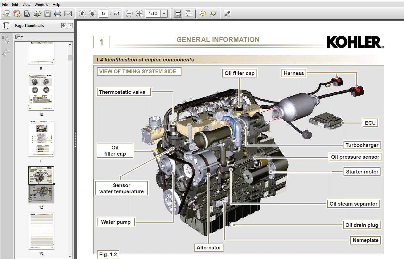
Components, Identification ofengine 12
Components,Electrical“43
N Configuration (chapter general configuration),
information on engine_ 12
Configuration (chapter assembly),
Information on engine__ 124
Configurations with balancer shafts (optional)
Connecting rod piston assembly
Coolant (chapter fiuids supply)
Coolant (chapter liquid drainage information)
Coolant_
Cooling circuit____
Crankcase_
Crankshaft ______
Cylinder head unit assembly__
Cylinder head unit disassembly
D
Definitions, Glossary and mm
DIAGNOSTIC IIIFORMATION_
Diagnostic tool error Iist
Diagrams, Performance __
Dimensions, Engine_
Disassembly (EGR), Exhaust fumes recycle circuit
Disassembly, Cylinder head unit
Disassembly, Electric components _
Disassembly, Engine block
Disassembly, Exhaust manifold
Disassembly, Flange unit
Disassembly, Injection circuit
Disassembly, Intake manifold
Disassembly, Lubrication circuit
Disassembly, Oil sump unit
Disassembly, Recommendations for
Disassembly, Timing system gear
Disassembly, Turbocharger
Disassembly, Water recirculation components
E
EGR Circuit assembly_
EGR valve replacement__
Electric component assemby
Electric components disassemblv
Electric system_
Electrical components
Electronic injector replacement_
Engine block assembly
Engine block disassembly
Engine dimensions
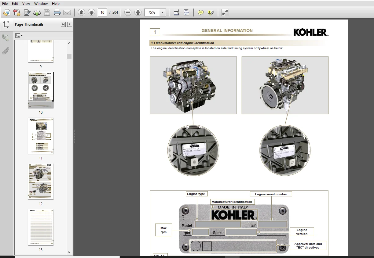
Engine identification, Manufacturer and
Engine oil (chapterliquid drainage information) _
Engine oil (chapter fluids supply)
Engine pulley and phonic wheel assembly_
Engine pulley and phonic wheel disassembly
Engine specifications____
Engine starting after storage
Engine storage (over 6 months) _
Engine storage (up to 6 months)
Engine, Intended use of the
Environmental impact, Safety and_
EPA regulations, Name plate for_
Error list, Diagnostic tool
Exhaust circuit, Intake and
Exhaust fumes recycle circuit disassembly (EGR)
Exhaust manifold assembly
Exhaust manifold disassembly_
F
Features, Battery_
Filter (cartridge replacement), Air
Flange unit assembly
Flange unit disassembly
FLUIDS SUPPLY INFORMATION
Foreword, Introduction
Fuel
Fuel filterreplacement
Fuel system
Fuel system assembly
G
Gear (for 3″ l 4″ PTO), Idler
GENERAL INFORMATION
General remarks__
Glossary and Definitions
H
Handling, Components
Heater (replacement) _
Highpressure pump replacement
High—pressure pump, liming system gear
I
Identification of engine components
Idler gear (for 3″ / 4‘” PTO)
INFORMATION ABOUT FAILURES
INFORMATION ABOUT OPTIONAL C OM PONHJ TS
INFORMATION FOR RB’LACING THE
FUNCTIONAL UNITS
ITIFORMAIION ON ADJUSTMENTS
Information on engine configuration
Information on engine configuration
(chapter general configuration)
Information on resources used in graphics software
POLARXL_____a_~aa~e__WWW“
Tnformation and safety signals
Injection circuit disassembly
Injector replacement, Electronic
Intake and exhaust circuit
Intake manifold assembly
Intake manifold disassembly__
Intended use of the engine
Introduction Foreword__
INTRODUCTION FOREWORD
L
LIQUID DRAINAGE INFOMATIONt
Location of safetysignals on engine _t
Lubrication circuit___2
Lubrication circuit disassembly_£
M
Maintenance, Periodic_t
Manufacturer and engine identification ‘
N
Name plate for EPA regulations _ ‘
0
Oil (chapter liquid drainage information), Engine_t
Oil (chapter fiuids supply), Engine 1!
Oil___ ‘
Oil cooler unit and oil filter replacementI
Oil dipstick in cylinder head_ 1!
Oil filter (disassembly and assembly), Remote 1]
Oil filter replacement, Oil cooler unit and_!
Oil pressure valve replacement I
Oil pump check _ 1:
Oil pump replacement_2
Oil sump unit assembly 1:
Oil sump unit disassembly_ 1 t
Oil vapour separator replacementt
P
Performance diagram__ ‘
Periodic maintenance:
Phonic wheel assembly, Engine pulley and 1‘
Phonic wheel disassembly, Engine pulley and_1‘
Phonic wheel replacement_W»2
Piston assembly, Connecting rod_ 1’
l POLARXL, lnfonnation on resources used in graphics
software _____ 1E
PolyV alternator belt (replacement and adjustment) 1!
PolyV belt, Tightening pulley and alternator for16
Possible causes and trouble shooting__18
Precautions, Safety _5
Preservation, Product ____ 6
Product pres ervation_ 6
R
Recommendations for cfisassembly8
Recommendations for overhauls and tuning 11
Recommendations, Assembly 12
Regulations forsafety and accident prevention
Remarks, General _5
Remote oil tflter (disassembly and assembly) 17
Replacement, Electronic injector6
Replacement, Fuel filter_8
Replacement, Highpressure pump__6
Replacement, Oil cooler unit and oil filter8
Replacement, Oil pressure valve 8
Replacement, Oil pump_ 7
Replacement, Oil vapour separator_8
Replacement, Phonic wheel 7
Replacement, Unit EGR coo!er~ 7
Replacement, Water pump_ 7
Rreplacement, EGR valve 7
s
Safety and environmental impacta_5
Safetysignals, information and _5
SAFETY INFORMATION __5
Safety precautions__5
Safety signals__6
Safety signals description 5
Safety signals on engine, Location of__6
Scrapping____
Sensors and switches _4
Shafts (replacement), Balancer 17
Signals description, Safetyc 5
Signals, Safety ____c6
Specifications, Engine
Startup, Before
Storage (over 6 months), Engine
Storage (up to 6 months), Engine
STORAGE INFORMATION_
Summary table of tightening torques and the use of sealants
Switches, Sensors and
System, Electric
System, Fuel
T
Tappet housings, Tappets and
Tappets and tappet housings
Tappets, Timing system and
TECHNICAL INFORMATION
Tightening pulley and alternator for PolyLV belt
fiming system and tappets a
Timing system gear assembly and high pressure pump
Timing system gear disassembly
TOOLS INFORMATION “0”
Trouble shooting, Possible causes
Tuning, Recommendations for overhauls and
Turbocharger disassembly
Turbo—compression
Turbocompress or assembly
U
Unit EGR cooler replacementa
Use of sealants, Summary table of tightening
torques
W
Water circuit assembly
_Water pump replacement_
Water recirculation components disassembly
(”WASTE GATE” valve, Adjustment_
3’” PTO (replacement/installation)
:4” PTO (replacement/ installation)
KOHLER DIESEL KDI 1903 TCR – 2504 TCR WORKSHOP MANUAL – PDF DOWNLOAD:
IMAGES PREVIEW OF THE MANUAL:
PLEASE NOTE:
- This is the same manual used by the DEALERSHIPS to SERVICE your vehicle.
- The manual can be all yours – Once payment is complete, you will be taken to the download page from where you can download the manual. All in 2-5 minutes time!!
- Need any other service / repair / parts manual, please feel free to contact us at heydownloadss @gmail.com . We may surprise you with a nice offer