
Komatsu 114 Series SAA6D114E-2 Diesel Engine Shop Manual SEBM024603 2004
Original price was: $44.95.$26.95Current price is: $26.95.
433-page Komatsu 114 Series shop manual for the SAA6D114E-2 diesel engine, covering specifications, system operation, testing, troubleshooting, disassembly, assembly, repair standards and component replacement procedures.
Description
Komatsu 114 Series SAA6D114E-2 Diesel Engine Shop Manual SEBM024603 2004
The Komatsu 114 Series SAA6D114E-2 Diesel Engine Shop Manual SEBM024603 2004 is a workshop-focused technical reference for the SAA6D114E-2 engine and the machine applications identified in the manual. Its coverage goes well beyond basic maintenance: the book explains engine construction and operating principles, provides inspection and maintenance standards, gives testing and adjustment procedures, walks through complete engine disassembly and assembly, and includes repair and replacement methods for reusable or serviceable components.
The application table links the SAA6D114E-2 engine to the PC300-7 hydraulic excavator, WA380-5 wheel loader, GD655-3A,3C and GD675-3A,3C motor graders, and CD110R-2 crawler carrier. Because dimensions, accessories, electrical equipment, power data and some component arrangements vary by machine model, the manual repeatedly identifies model-specific differences where they matter.
File Details
- Manual type: Shop Manual – Diesel Engine
- Brand: Komatsu
- Engine series: 114 Series
- Engine model: SAA6D114E-2
- Document number: SEBM024603
- Date: 2004
- Printed marking: 03-04(03) (3)
- Language: English
- Page count: 433
- File format: PDF
Engine and Machine Coverage
This Komatsu 114 Series diesel engine shop manual centers on the six-cylinder SAA6D114E-2. The general specification section identifies a 114 x 135 mm bore and stroke and a firing order of 1-5-3-6-2-4. It also provides model-dependent engine dimensions, dry weights, flywheel horsepower, maximum torque, high- and low-idle speeds, lubricating oil refill quantities, coolant quantity, alternator and starting-motor ratings, battery arrangements, and turbocharger information. Engine performance curves are supplied separately for the PC300-7/CD110R-2, WA380-5, GD655-3A,3C and GD675-3A,3C applications.
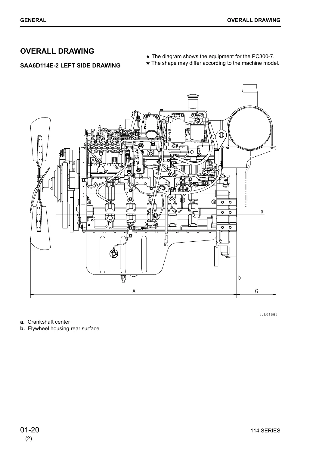
Overall engine drawings show left-side and front views, while the dimension table gives reference measurements for test-bench installation. This makes the manual useful not only when an engine is still installed in a machine, but also during workshop inspection, overhaul, bench work and reassembly.
What the Manual Helps You Work On
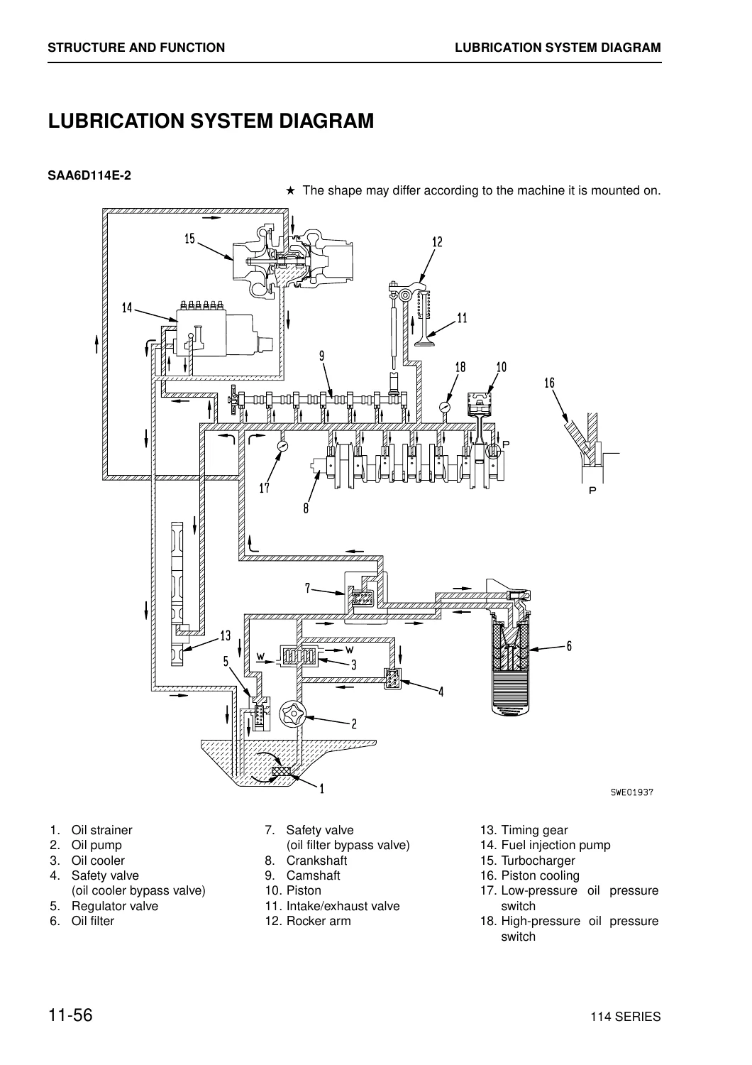
The structure and function material follows the engine system by system. Intake and exhaust coverage explains the air cleaner, turbocharger, waste gate operation and air-cooled aftercooler. The main engine section covers the cylinder head, cylinder block, wet cylinder liners, crankshaft, pistons and rings, connecting rods, vibration damper, timing gears, camshaft and valve mechanism. Lubrication coverage includes the oil circuit, trochoid oil pump, oil filter, oil cooler, regulator valve and safety valve. Fuel-system material covers the Bosch P3000 injection pump, Bosch RSV centrifugal all-speed governor, fuel filter, injection nozzles and fuel-cut solenoid. Cooling and electrical sections include the water pump, thermostat, fan drive, alternators, starting motors and electrical intake-air heater.
Maintenance-standard pages place wear limits, clearances, runout limits, dimensions and tightening values beside the related components. Examples include cylinder-head distortion and bolt tightening sequence, cylinder-block and bearing dimensions, cylinder-liner bore criteria, crankshaft inspection limits, piston and ring measurements, connecting-rod checks, camshaft and valve timing values, valve and guide dimensions, rocker-arm and tappet clearances, flywheel runout, oil-pump clearances and turbocharger rotor criteria. The manual also supplies standard tightening-torque tables, capscrew identification and torque values, pipe-plug torques, wire codes, conversion tables and SI-unit guidance.
Testing, Adjustment and Troubleshooting
The testing and adjusting section is organized around real workshop diagnosis. It lists special tools for the intake/exhaust system, cylinder head, engine, fuel system, accessory components, electrical components and engine performance testing. Intake and exhaust procedures cover restriction checks, turbocharger rotor play, waste-gate checks and adjustment, exhaust resistance and turbocharger replacement. Engine checks include valve mechanism and cylinder-head inspection, air and fuel checks, valve clearance, compression, piston-ring sealing, valve sealing, head-gasket sealing, fuel-nozzle protrusion, gear-train items, piston/connecting-rod checks, crankshaft/main-bearing checks, cylinder-block checks and flywheel-housing/flywheel checks.
Lubrication troubleshooting addresses high or low pressure, regulator-valve operation, oil level, filters, pressure gauges, suction tubing, bearings and oil pump, oil dilution, cooling water in oil and fuel in oil. Fuel-system procedures include fuel-injection-pump calibration data, running-in standards, performance-test criteria, fuel-feed-pump testing, fuel cut-off solenoid adjustment, air in the fuel system, water-separator and fuel-filter checks, high-pressure fuel piping, injection-nozzle testing, fuel-drain piping, bleeding procedures and injection-pump timing. Cooling-system troubleshooting covers the radiator cap, water pump, radiator/fan arrangements, thermostat and temperature-related checks. The section finishes with standard-value tables for testing, adjusting and troubleshooting and an engine troubleshooting section.
Chapters Covered
- 01 General
- Applicable machine
- Specification
- Overall drawing
- Weight table
- Engine performance curve
- 11 Structure and Function, Maintenance Standard
- Air intake device, exhaust manifold and air cleaner
- Turbocharger and aftercooler
- Cylinder head, cylinder block and cylinder liner
- Main circulation part, crankshaft, piston/piston ring/piston pin and connecting rod
- Vibration damper, timing gear portion, front gear cover and camshaft timing pin
- Timing gear, camshaft and valve mechanism
- Valve/valve guide and rocker-arm shaft/push rod/tappet
- Oil pan, flywheel and flywheel housing
- Lubrication system diagram, oil pump, oil filter and oil cooler
- Regulator valve and safety valve
- Fuel system diagram, fuel injection pump, timing lock pin, fuel filter and fuel injection nozzle
- Fuel cut solenoid
- Cooling system diagram, water pump drive, water pump and thermostat
- Fan drive, alternator, starting motor and starting aid
- 12 Testing and Adjusting
- Special tool list
- Intake and exhaust system troubleshooting and turbocharger testing
- Engine troubleshooting, compression and sealing checks
- Valve clearance and engine component inspection
- Lubricating system troubleshooting
- Fuel injection pump calibration data and running-in standard
- Performance test criteria
- Fuel feed pump, fuel cut-off solenoid and fuel-system testing
- Fuel-system bleeding and injection timing
- Cooling-system troubleshooting
- Standard value table for testing, adjusting and troubleshooting
- Troubleshooting of engine (S mode)
- 13 Disassembly and Assembly
- Special tools for disassembly and assembly
- Overall disassembly of engine
- Removal of fuel, intake, exhaust, cooling and electrical accessories
- Removal of cylinder head, water pump, damper, gear cover, flywheel and oil pan
- Removal of camshaft, pistons, bearings, crankshaft and cylinder liners
- Assembly of engine
- Installation of liners, bearings, crankshaft, pistons, gears and camshaft
- Installation and checking of flywheel housing and flywheel
- Cylinder-head, rocker-lever, valve-clearance and injector installation
- Turbocharger, cooling, alternator and belt installation
- Fuel-injection-pump, fuel-line, seal and accessory installation
- 15 Repair and Replacement of Parts
- Repair guideline and inspection requirements
- Coil thread insert repair methods
- Taper-thread plug and emergency filler-metal repair methods
- Inspection for reuse of cylinder block
- Expansion plugs, pipe plugs and camshaft bushings
- Cleaning and inspection of cylinder liners and pistons
- Cleaning and inspection of crankshaft, main bearings and bearing caps
- Connecting-rod bearing and connecting-rod inspection and repair
- Replacement of connecting-rod bushings
- Valve guides, valve seat inserts, valve springs, stem seals and valves
- Grinding and assembly of valves and valve seat inserts
Taken together, these chapters turn the Komatsu 114 Series SAA6D114E-2 Diesel Engine Shop Manual SEBM024603 2004 into a complete engine-workshop reference: first understand the system and its standards, then test and diagnose it, disassemble it with the specified precautions and tools, inspect components against service criteria, and rebuild or repair the engine using the documented sequences and tightening values.
Detailed Overhaul Procedures and Workshop References
The disassembly and assembly coverage is especially useful for major engine work. Procedures include preparation and cleaning, draining oil and coolant, removing filters and fuel piping, removing the injection pump, turbocharger and aftercooler, removing the cylinder head and cooling components, taking off the flywheel and housing, removing the oil pan and suction tube, extracting the camshaft, pistons, bearings, crankshaft and cylinder liners, and then rebuilding the engine in the reverse direction with measurement checks inserted at the appropriate stages.
Assembly instructions include liner installation, piston-ring end-gap measurement, piston and connecting-rod installation, gear-housing and oil-pump work, camshaft installation, rear and front crankshaft seals and wear sleeves, flywheel-housing alignment checks, flywheel runout checks, valve-clearance adjustment, injector and fuel-pipe installation, turbocharger and belt installation, and fuel-injection-pump timing. Special tool numbers, wrench sizes, cautions, component weights and tightening torques appear throughout the procedures where the manual specifies them.
The repair section adds procedures for evaluating whether parts can be reused and for restoring selected components. It covers cylinder-block inspection, threaded-hole repair, expansion plugs, camshaft bushings, cylinder liners, pistons, crankshaft and bearings, connecting rods and bushings, and cylinder-head valve components. These procedures are supported by dimensional limits and inspection methods rather than general advice, helping a technician decide whether a part can remain in service, needs machining or corrective work, or should be replaced.
Get the SAA6D114E-2 Repair Information When You Need It
Use the Komatsu 114 Series SAA6D114E-2 Diesel Engine Shop Manual SEBM024603 2004 when you need to diagnose engine performance problems, check wear against maintenance standards, measure and adjust fuel or valve-system settings, remove and install major engine components, carry out a full strip-down and rebuild, or follow documented repair procedures for serviceable parts. Having the correct procedures, limits, torque values and model-specific references in one manual helps reduce guesswork during workshop work and gives you a consistent reference from initial diagnosis through final assembly.
Delivery is instant as a PDF after payment, with no physical shipping. The manual can be opened on compatible computers, tablets and phones and can be printed for workshop use, so the technical information is available at the bench, beside the machine or wherever the repair is being carried out.
Reviews
There are no reviews yet.