
Komatsu 125-3 Series SA6D125E-3 SAA6D125E-3 Diesel Engine Shop Manual SEBM024208 – 2004
Original price was: $49.95.$29.95Current price is: $29.95.
Komatsu 125-3 Series diesel engine shop manual for SA6D125E-3 and SAA6D125E-3 engines. Covers specifications, structure and function, maintenance standards, testing and adjusting, troubleshooting, disassembly and assembly, and component repair procedures in a 374-page PDF.
Description
Komatsu 125-3 Series SA6D125E-3 SAA6D125E-3 Diesel Engine Shop Manual SEBM024208 – 2004
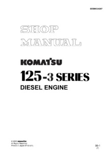
The Komatsu 125-3 Series SA6D125E-3 SAA6D125E-3 Diesel Engine Shop Manual SEBM024208 – 2004 is a comprehensive 374-page workshop reference for Komatsu 125-3 Series diesel engines, covering the SA6D125E-3 and SAA6D125E-3 engine families and the engine configurations used across the applicable machines identified in the manual. It combines construction and operating explanations with maintenance standards, inspection limits, testing procedures, adjustment methods, troubleshooting information, complete engine disassembly and assembly sequences, and repair or replacement procedures for major engine parts. Publication number SEBM024208 is shown on the manual, with a 2004 copyright and the printing mark 04-04 (01).
File Details
- Manual type: Shop Manual
- Brand: Komatsu
- Series: 125-3 Series Diesel Engine
- Engine models: SA6D125E-3 and SAA6D125E-3
- Language: English
- Page count: 374 pages
- File format: PDF
- Publication number: SEBM024208
- Date marking: 2004; Printed in Japan 04-04 (01)
Engine and Machine Coverage
This Komatsu 125-3 Series diesel engine shop manual distinguishes between in-line fuel injection pump and common rail system specifications. The in-line fuel injection pump material includes the SAA6D125E-3 used with the WA430-5. Common rail coverage includes the SA6D125E-3 and SAA6D125E-3 used in the machine applications listed by the manual, including D65EX-15, D65PX-15, D85EX-15, D85PX-15, WA470-5, WA480-5, HM300-1, PC400-7, PC450-7 and HD255-5. Because details differ according to machine model, the manual repeatedly identifies the relevant engine and machine combination alongside drawings, specifications, test data and component information.
The engine description identifies the 125E-3 configuration as an in-line, six-cylinder, water-cooled, direct-injection, four-cycle diesel engine. The general specification pages provide machine-specific figures for dimensions, rated output, maximum torque, high- and low-idle speed, dry weight, lubricating-oil quantity, cooling-water quantity, charging and starting equipment, batteries, turbocharger and aftercooler arrangements. General assembly drawings show left, right, front and rear views for applicable engine installations, while separate engine performance curves give output and torque characteristics for individual machine applications.
Structure, Function and Maintenance Standards
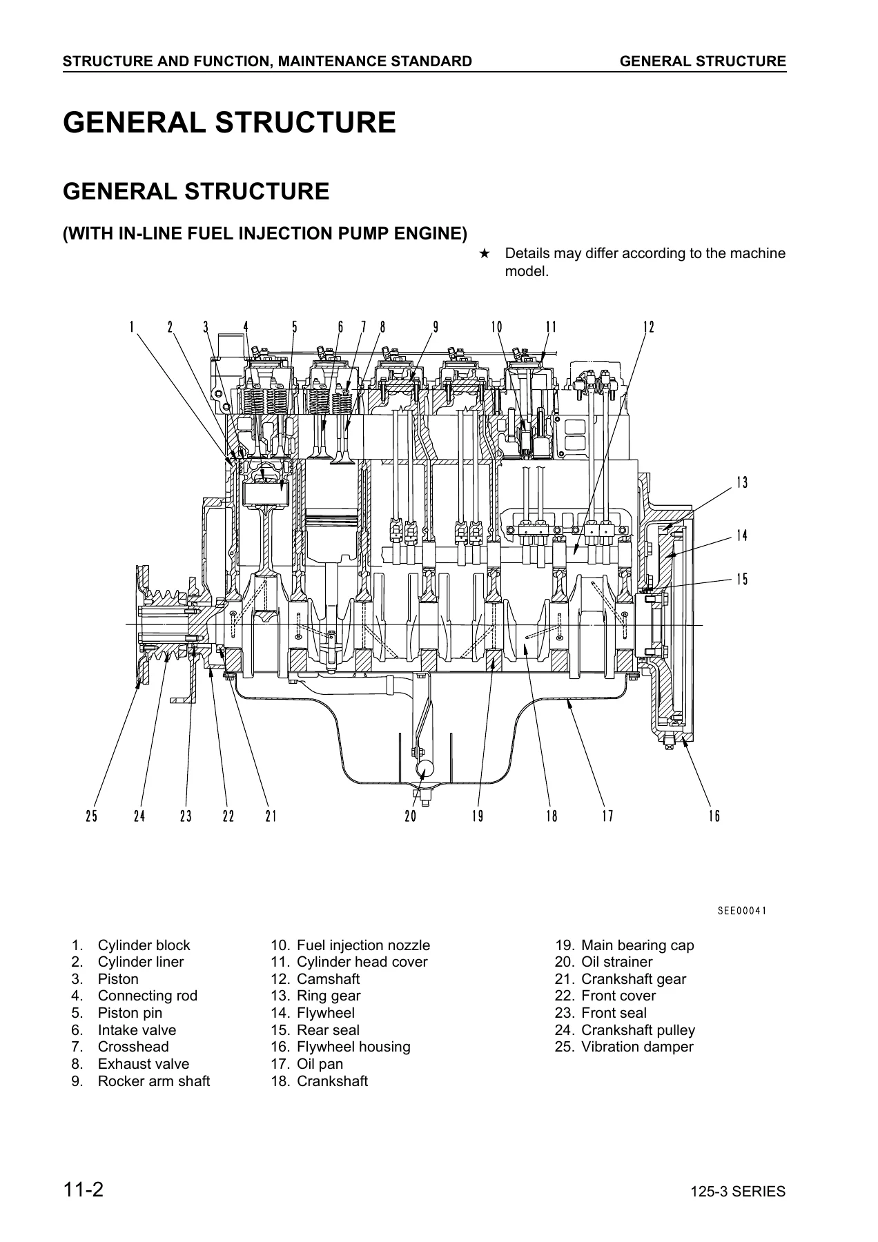
A major part of the Komatsu 125-3 Series SA6D125E-3 SAA6D125E-3 Diesel Engine Shop Manual SEBM024208 – 2004 explains how the engine and its supporting systems are built and how they operate. Cross-sectional drawings identify the cylinder block, liners, pistons, connecting rods, crankshaft, valves, rocker gear, camshaft, timing gears, flywheel, seals, lubrication components and other internal parts. Intake and exhaust coverage includes the air cleaner, SCHWITZER S400 turbocharger and aftercooler arrangements. The lubrication section traces oil flow through the oil pan, strainer, gear-type oil pump, cooler, filter, crankshaft, piston cooling nozzles, camshaft, valve gear and turbocharger. Cooling-system drawings cover the radiator circuit, water pump, thermostat, oil cooler and corrosion resistor.
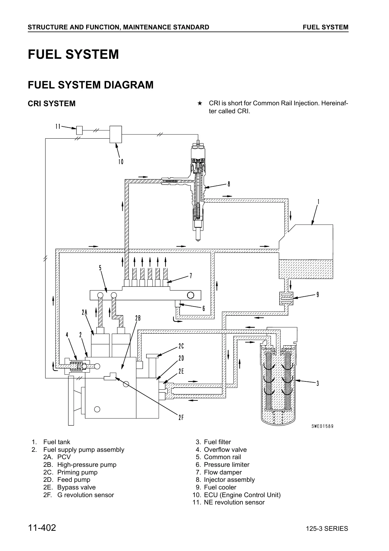
The common rail fuel-system material is especially detailed. It explains the fuel supply pump, high-pressure pump, PCV discharge control valves, feed pump, common rail, pressure sensor, flow dampers, pressure limiter, injectors, ECU and engine sensors. Operation diagrams show how the system controls injection amount, timing and rail pressure. The manual also describes injector operation and the electrical circuit, along with crank-angle and cylinder-judgement sensors, water-temperature and fuel-temperature sensors. Maintenance-standard tables provide measurable criteria, clearances, wear limits, runout limits and tightening requirements for components such as the cylinder head, cylinder block, liner, crankshaft, pistons, connecting rods, timing gears, camshaft, valve train, oil pump and cooling system.
Testing, Adjustment and Troubleshooting
Testing and adjusting procedures turn the specifications into practical workshop checks. The manual provides testing data, electrical-component standard values and a testing-tool list, then gives step-by-step methods for measuring intake-air boost pressure, exhaust temperature, compression pressure, blow-by pressure, engine oil pressure and fuel pressure. It covers valve-clearance adjustment for the relevant fuel-system configurations, engine speed sensor adjustment, fuel injection timing for the in-line fuel injection pump specification, and checks associated with engine performance.
Fuel-system service instructions include precautions for the common rail system, releasing remaining fuel pressure, bleeding air from the fuel circuit, reduced-cylinder mode operation and leakage inspection. The troubleshooting portion is divided into engine-system and electrical-system diagnosis. Standard values and judgement criteria are supplied for items such as engine speed, intake resistance, boost pressure, exhaust pressure and temperature, valve clearance, compression pressure, blow-by, oil pressure and electrical sensors or actuators. Calibration data and performance-test sections provide further reference material for workshop testing and run-in work.
Disassembly, Assembly and Component Repair
The overhaul section follows a practical removal and reassembly sequence rather than stopping at general theory. General disassembly begins with preparation and the removal of external components, then progresses through the starting motor, cooling and lubrication parts, turbocharger and manifolds, filters, wiring, fuel-system components, head cover, injectors, rocker mechanism, cylinder heads, oil pan, flywheel and housing, damper, front cover, water pump, camshaft, oil pump, idler gears, piston cooling nozzles, piston-and-connecting-rod assemblies, crankshaft and cylinder liners. The general assembly section then takes the engine back through installation of these core components, with procedures and tightening information placed where the work is performed.
The dedicated repair and replacement chapter goes further into corrective work on individual parts. It includes valve seat insert replacement, nozzle holder sleeve replacement, valve guide replacement, crosshead guide replacement, valve grinding, grinding the cylinder-head fitting face and pressure testing. Cylinder-block repair subjects include cam bushing replacement, cam gear replacement, flywheel ring gear replacement, engine rear seal replacement, connecting-rod small-end bushing replacement, main bearing cap replacement, crankshaft grinding and wear-sleeve replacement where equipped. These procedures make the Komatsu 125-3 Series SA6D125E-3 SAA6D125E-3 Diesel Engine Shop Manual SEBM024208 – 2004 useful for both diagnosis before teardown and dimensional judgement during rebuild work.
Chapters Covered
- 01 General
- Outline and applicable machines
- Specifications
- General assembly drawings
- Weight table
- Engine performance curves
- 11 Structure and Function, Maintenance Standard
- General structure
- Intake and exhaust system: air cleaner, turbocharger and aftercooler
- Engine body: cylinder head, cylinder block, cylinder liner, main circulation system, crankshaft, piston, connecting rod, flywheel and flywheel housing, vibration damper, timing gear, valve mechanism, camshaft, cam follower and push rod, valve and valve guide, rocker arm shaft and crosshead
- Lubrication system: lubrication diagram, oil pump, oil filter and oil cooler
- Fuel system: fuel-system diagram, CRI system, fuel piping, fuel cooler and fuel filter
- Cooling system: cooling chart, water pump, thermostat and corrosion resistor
- Electrical system: alternator mounting, alternator, starting motor and starting aid
- 12 Testing and Adjusting, Troubleshooting
- Testing and adjusting data and electrical standard values
- Testing and adjusting tool list
- Boost pressure, exhaust temperature, compression, blow-by, oil pressure and fuel pressure measurement
- Valve clearance and engine speed sensor adjustment
- Fuel injection timing
- Common rail fuel-system handling, pressure release and air bleeding
- Reduced-cylinder mode and fuel-leakage checks
- Engine stop motor lever adjustment
- Calibration data, run-in standard and performance test standards
- Engine-system troubleshooting and electrical-system troubleshooting
- 13 Disassembly and Assembly
- Method of using the manual and operating precautions
- Special tool list and sketches
- General disassembly
- General assembly
- 15 Repair and Replacement of Parts
- Cylinder head repairs: valve seat insert, nozzle holder sleeve, valve guide, crosshead guide, valve and fitting-face work, pressure test
- Cylinder block repairs: cam bushing, cam gear, flywheel ring gear, rear seal, connecting-rod bushing, main bearing cap, crankshaft grinding and wear sleeve
Taken as a whole, the manual gives a technician a continuous reference from engine identification and system operation through measurement, fault isolation, teardown, inspection, dimensional judgement, component repair and reassembly. The combination of labeled drawings, circuit and flow diagrams, specification tables, service limits, torque data, test procedures and overhaul sequences helps connect a symptom or measured condition to the correct workshop operation.
Service, Diagnose and Rebuild with the Correct Reference
The Komatsu 125-3 Series SA6D125E-3 SAA6D125E-3 Diesel Engine Shop Manual SEBM024208 – 2004 supports workshop jobs ranging from valve adjustment and pressure checks to common rail diagnosis, fuel-system service, cylinder-head work and complete engine overhaul. Using the procedures, maintenance standards, tightening values and machine-specific test data in the manual helps technicians check components against the specified criteria instead of relying on guesswork during repair or reassembly. This is an instant PDF download after payment, with no physical shipping required. The file can be opened on compatible phones, tablets and computers and printed when a paper workshop reference is preferred.
Reviews
There are no reviews yet.