
Komatsu 930E-2 Dump Truck Shop Manual CEBM012200 – PDF Download
Original price was: $69.95.$49.95Current price is: $49.95.
Complete Komatsu 930E-2 Dump Truck Shop Manual (CEBM012200) in PDF — covering the SSDA16V160 engine, AC electric propulsion, Hydrair II suspensions, wet disc brakes, hydraulic system and full system schematics for serial numbers A30296, A30297 and A30300.
Description
Komatsu 930E-2 Dump Truck Shop Manual — Publication CEBM012200
This is the complete Komatsu 930E-2 Dump Truck Shop Manual, published under document number CEBM012200 and written for the technicians who service, diagnose and rebuild the AC electric drive 930E-2. It covers the truck from the ground up: the SSDA16V160 diesel, the alternator and inverter propulsion chain, the motorized wheel assemblies, the Hydrair II suspension cylinders, the all-hydraulic wet disc brake circuit, the hoist and steering hydraulics, and the operator’s cab. Every procedure is written as a repair sequence — component descriptions first, then removal, disassembly, inspection, assembly and installation — with the torque values, clearances, wear limits and service capacities called out directly in the text.
File Details
- Manual type: Shop Manual
- Brand: Komatsu
- Model: 930E-2 Dump Truck
- Publication number: CEBM012200
- Serial numbers covered: A30296, A30297, A30300
- Language: English
- File format: PDF
- Page count: 924 pages
Chapters Covered
- Section A — General Information
- Section B — Structures
- Section C — Engine Systems
- Section D — Electric System (24 VDC, Non-Propulsion)
- Section E — Electric Propulsion and Control
- Section G — Drive Axle, Spindles and Wheels
- Section H — Hydrair® II Suspensions
- Section J — Brake Circuit
- Section L — Hydraulic System
- Section M — Options and Special Tools
- Section N — Operator’s Cab
- Section P — Lubrication and Service
- Section Q — Alphabetical Index
- Section R — System Schematics
Section A — General Information
Component descriptions and full truck specifications for the 930E, including engine data (Komatsu SSDA16V160, 16-cylinder, 4-stroke, 2700 HP / 2014 kW @ 1900 RPM), the AC electric drive system, dynamic retarding ratings, the 24 VDC battery electric system, service capacities, hydraulic system pressures and flows, service brake data and steering geometry. Also contains the general safety and operating instructions, the warning and caution plates list, the standard torque charts (SAE Grade 5 and Grade 8, 12-point Grade 9, metric Class 10.9, JIC swivel nuts, pipe thread, O-ring boss and O-ring face seal), conversion tables, and the storage and idle-machine preparation procedure.
Section B — Structures
Deck components, grille, hood and ladder removal and installation, dump body removal and installation with the hoist cylinder upper mount detail, body pad inspection and adjustment, body guide wear limits, body-up retention cable procedure, rock ejector inspection (Type I and Type II), and the fuel tank group — removal, installation, internal cleaning, fuel gauge sender, low fuel switch, breather valve and the left side fill receiver assembly.
Section C — Engine Systems
Power module roll-out procedure with lifting points and weights, radiator and cooling system service, the internal tube-and-seal rebuild procedure for the L&M radiator (breaker tool, installation tool, seal installation and pressure testing), powertrain removal of the alternator from the engine with the full shim-measurement and end-play procedure, engine removal and installation, air cleaner service including precleaner tube cleaning and filter element inspection, and the fan clutch — disassembly, cleaning, inspection, assembly and test procedure with the special service tools.
Section D — Electric System (24 VDC, Non-Propulsion)
The complete 24 VDC supply system, battery maintenance and troubleshooting, battery control box, isolation diodes, battery disconnect switches, auxiliary battery connectors and the battery equalizer. Also covers the 24 VDC electrical system components behind the passenger seat: tail light resistor diode assemblies, the 5 minute idle timer circuit and its test, inclinometer, brake warning buzzer, the Alarm Indicating Device (AID) system with each printed circuit card explained, the electrical interface cabinet and relay boards RB1 through RB7, body-up switch and hoist limit switch adjustment, the circuit breaker chart, and the Niehoff battery charging alternator — removal, on-truck troubleshooting, static tests, overhaul and assembly.
Section E — Electric Propulsion and Control
Propulsion system components and general system description, the Truck Control Interface (TCI) panel and Diagnostic Information Display (DID) with the full fault code tables for the PSC, Inverter 1 and Inverter 2, PSC software functions and state machine, event processing, data packs, serial communications, and the electronic accelerator and retard pedals. The AC Drive System Electrical Checkout Procedure covers truck shutdown procedures (normal and after system failure), system checkout with battery power off and on, CPU battery checks, TCI, PSC and inverter programming, load testing, on-board load testing with the parasitic loss curves, and troubleshooting for the phase modules, chopper modules, auxiliary blower control system and IGBTs.
Section G — Drive Axle, Spindles and Wheels
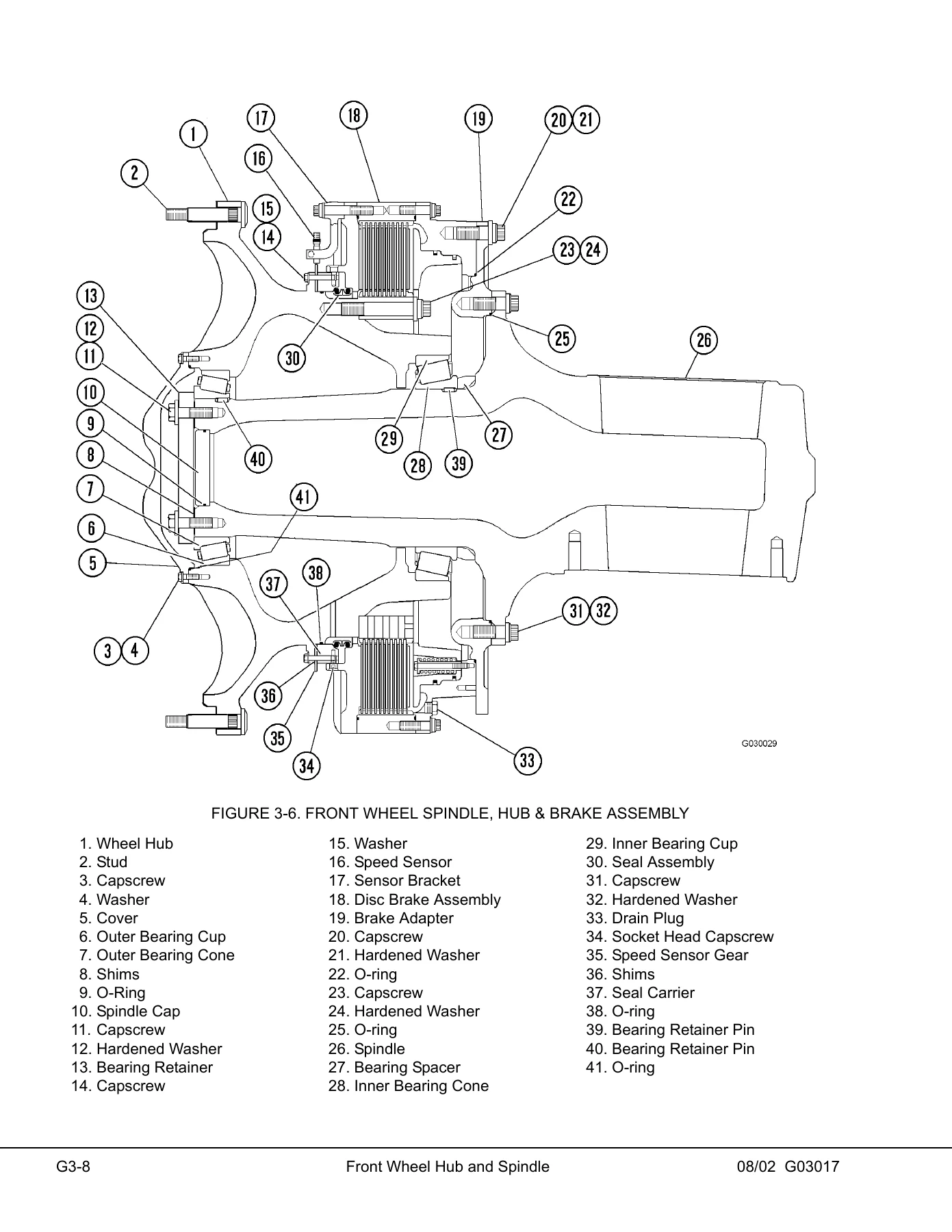
Tires and rims — front and rear removal and installation with the full wheel nut tightening sequence and torque, rim disassembly and tire mounting procedures. Front wheel hub and spindle removal using the spindle removal tool, disassembly, cleaning and inspection, wheel bearing adjustment with the shim pack calculation, brake installation and the seal assembly gap check. Steering cylinder and tie rod removal, installation and bearing replacement, spherical bearing wear limits, and toe-in adjustment. Rear axle housing attachment — pivot pin, pivot eye bearing, pivot eye repair and anti-sway bar. Rear axle housing and wheel motor removal and installation, plus wheel motor gear oil filtering, particle size analysis, flushing and the element specification charts for oil sampling.
Section H — Hydrair® II Suspensions
Front suspension removal and installation with the turn-of-the-nut tightening procedure for the mounting capscrews, minor repairs covering the lower bearing and seals, and major suspension rebuild. Rear suspension removal using the pin removal tool kit, installation, disassembly, cleaning and inspection, and assembly. The oiling and charging procedure section covers the Hydrair charging kit, support block dimensions, front and rear oiling and nitrogen charging heights and pressures, and the oil and nitrogen specifications chart with the friction modifier mixing instructions.
Section J — Brake Circuit
Service brake circuit, secondary braking and automatic apply, parking brake circuit, brake lock circuit and the warning circuit. Component service covers the brake valve rebuild (with rebuild criteria, disassembly, cleaning, assembly and the bench test and adjustment procedure), differential pressure switch, dual relay valve, hydraulic brake accumulators in the hydraulic components cabinet and frame mounted accumulators with charging procedures. The brake circuit check-out procedure includes the initial system set-up, service brake system check-out and failure modes check-out with a data sheet. Also covers the wet disc brake assembly — operation, wear indicator check, removal and installation, rebuild, floating ring seal assembly and installation, and the bleeding procedure — plus the parking brake inspection, removal, installation, disassembly, cleaning, assembly and bleeding procedure.
Section L — Hydraulic System
Hydraulic pump module, hoist circuit operation, steering circuit operation and the disc brake cooling system. Component repair covers the hoist pump (removal, installation, disassembly, inspection, assembly and troubleshooting), the hydraulic tank, tank strainers and tank breathers. The steering circuit section covers the steering control unit, the bleeddown manifold valve with the flow amplifier system operation diagrams for no-steer, steering left, steering right and external shock load, the steering pump with its pressure control schematic, steering circuit component repair including the flow amplifier rebuild, steering cylinders, steering and brake pump, and the steering accumulators with the charging procedure. High pressure filters and the hydraulic check-out procedure with the data sheets are also included.
Section M — Options and Special Tools
Fire control systems (manual and the Checkfire electric detection and actuation system with inspection and maintenance schedules, troubleshooting and in-case-of-fire procedures), the special tool group listing with part numbers and use, the Payload Meter III on-board weighing system (operation, component description, operator display and switch, payload operation and calculation, PC software overview, downloading and configuration, data analysis, troubleshooting and the PLMIII check-out procedure), and the reserve engine oil system with operation, service, troubleshooting and schematics.
Section N — Operator’s Cab
Truck cab description, preparation, removal and installation. Cab door removal, installation, adjustment, jamb bolt adjustment, handle plunger adjustment, door glass replacement, window regulator replacement, handle and latch assembly replacement and door and hinge seal replacement. Glass replacement for adhesive bonded windows and for the windshield and rear glass. Cab components — windshield wipers (motor, arm and linkage), windshield washer. Operator comfort — the operator seat with all adjustments, the heater and air conditioner operation, components, air conditioning system principles and components, electrical circuit, system servicing, PAG oil handling, refrigerant handling, service tools and equipment, performance test, leak testing, system repair, compressor clutch servicing, refrigerant recovery and recycling, evacuating and charging, and the full troubleshooting by manifold gauge set readings and the preventative maintenance schedule. Operator cab controls covers the steering column, steering wheel and controls, dynamic retarding, the grade/speed retard chart, heater and air conditioner controls, instrument panel, overhead panel and displays, center console, payload meter and the instrument panel and indicator lights with the full overhead status and warning indicator descriptions.
Section P — Lubrication and Service
Service capacities, hydraulic tank service, wheel motor service, coolant level check and radiator filling procedure, reserve engine oil system filling, the lubrication chart, and the 10 hour (daily), 50 hour, 100 hour, 250 hour, 500 hour, 1000 hour, 2500 hour and 5000 hour lubrication and maintenance checks. Also includes the automatic lubrication system — general description, system components, normal operation, pressure failure detection circuits, injector operation with the four-stage diagrams, lubricant requirements, system priming, pump housing oil level, pump pressure control adjustment, injector adjustment, system checkout, lubrication cycle timer check and adjustment, filter assembly, pump rebuild and the system troubleshooting chart.
Section R — System Schematics
Hydraulic supply and brake cooling schematic, hydraulic brake system schematic, Payload Meter III electrical system schematic, PLM III hook-up wiring for the 730E, 830E and 930E, and the full electrical schematic.
About the 930E-2
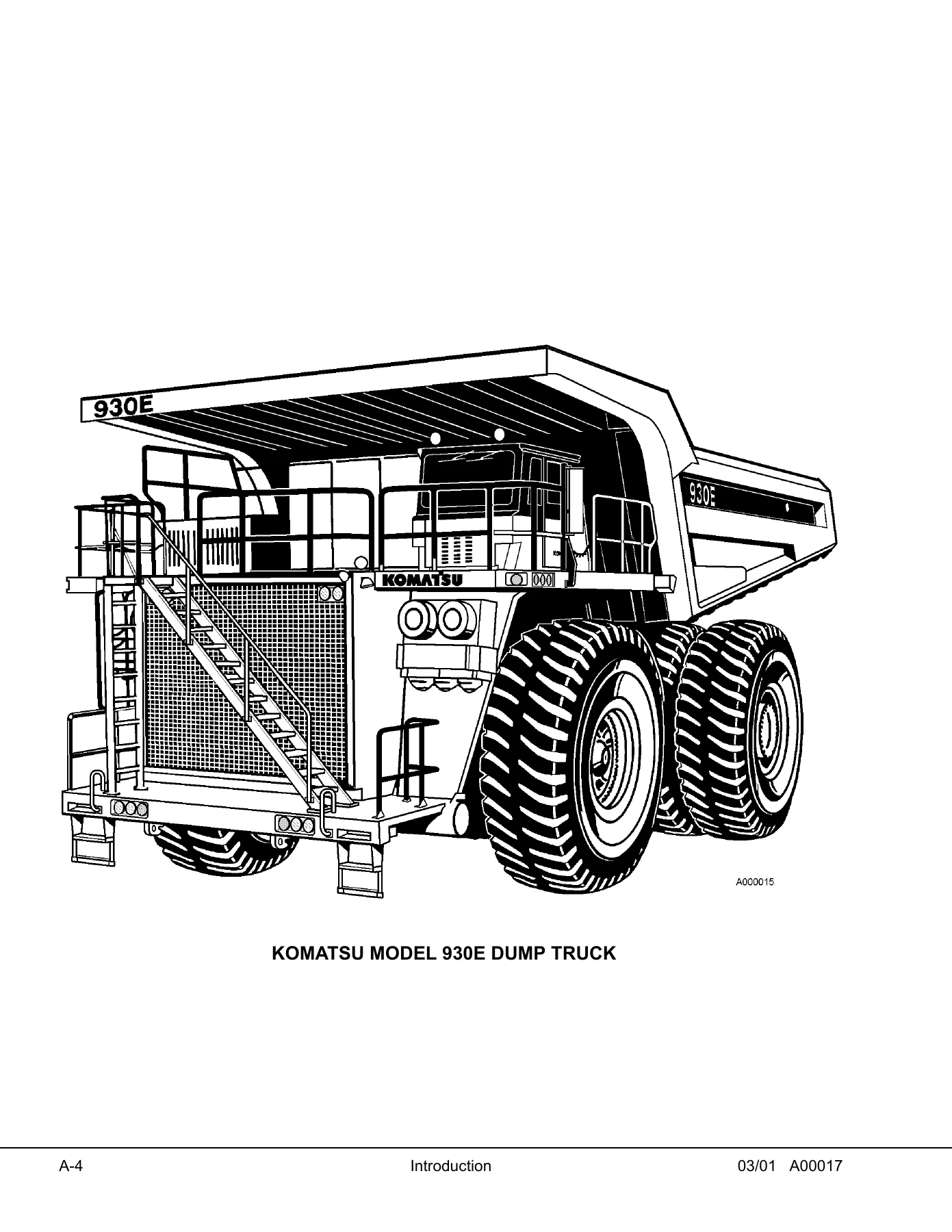
The 930E is an off-highway, rear dump truck with AC electric drive. Gross vehicle weight is 1,100,000 lbs (498,960 kg). The diesel engine drives an in-line alternator at engine speed; the alternator produces AC current that is rectified to DC inside the main control cabinet, then converted back to AC by inverters. Two wheel motors attached to the rear axle housing use three-phase AC induction motors with full-wave AC power, and convert electrical energy back to mechanical energy through built-in gear trains. Cooling air is provided by a dual impeller in-line blower mounted on the alternator. Service brakes at each wheel are oil-cooled multiple disc brakes applied by an all-hydraulic actuation system, and the parking brake is a dry disc type mounted inboard on each rear wheel motor, spring-applied and hydraulically released with wheel speed application protection.
What This Komatsu 930E-2 Shop Manual Lets You Do
With this manual on hand you can pull and rebuild the power module, set the engine-to-alternator shim packs and verify crankshaft end-play, adjust the wheel bearing preload with a calculated shim pack, charge the Hydrair II suspensions to the correct oil height and nitrogen pressure, rebuild the wet disc brakes and set the floating ring seal gap, bench-test the brake valve, chase down every fault code the DID panel can throw at you, work through the hoist and steering circuit pressures, and follow the daily through 5000-hour maintenance intervals. That matters on a truck of this size: the correct torque sequence on a wheel motor mounting flange, the right preload on a spindle bearing, or the correct nitrogen charge in a suspension cylinder is the difference between a truck that goes back to work and one that comes back with a failure. Every procedure in the PDF is the sequence Komatsu wrote for the 930E-2, not a generic guess.
IMAGES PREVIEW
Instant PDF Delivery
The manual is delivered as a PDF download immediately after checkout — no shipping, no waiting on a courier. Read it on a laptop in the shop office, on a tablet at the truck, or print the pages you need and take them to the job. Wiring diagrams, exploded views and torque tables print cleanly, and you can keep the whole 924-page shop manual in the toolbox instead of on a shelf.
Reviews
There are no reviews yet.