
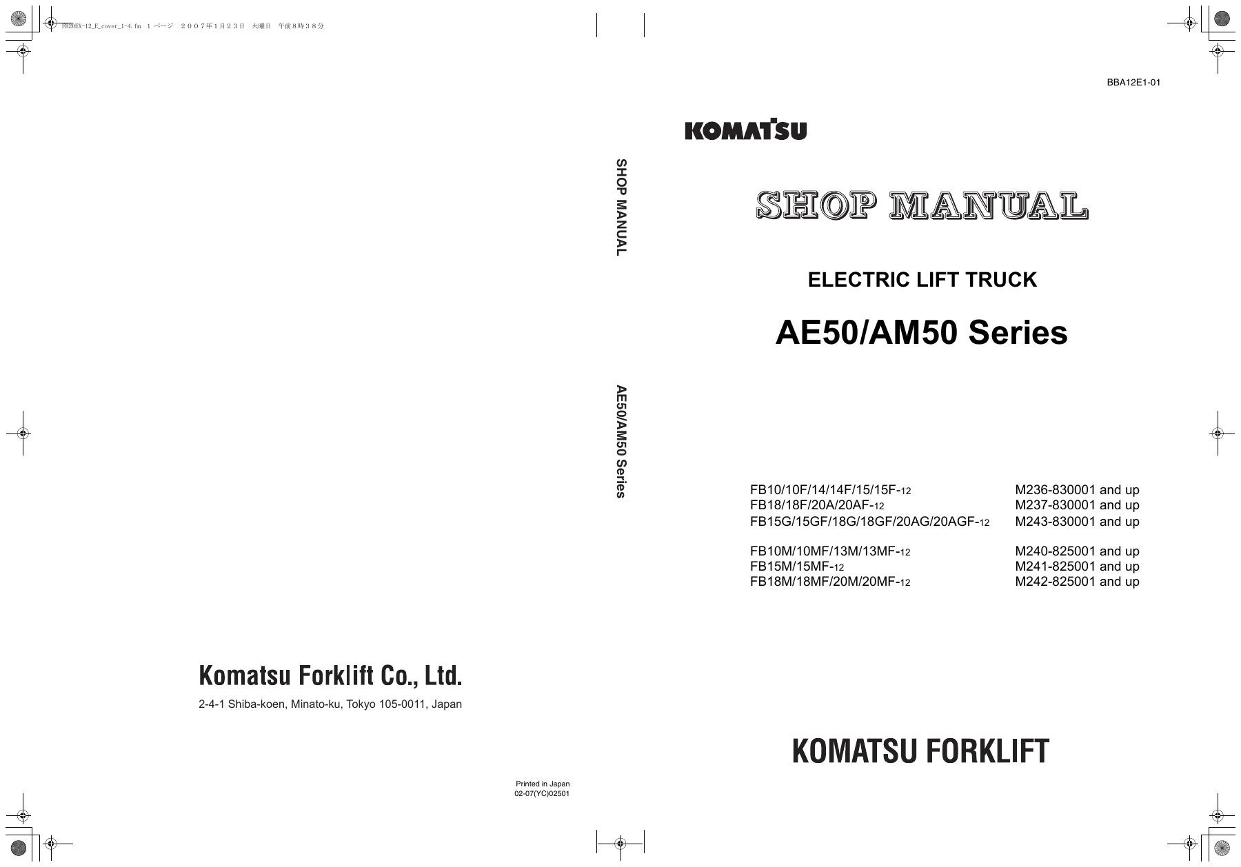
Komatsu AE50/AM50 Series Electric Forklift Shop Manual – FB10 FB14 FB15 FB18 FB20 Repair PDF
Original price was: $52.95.$34.95Current price is: $34.95.
Complete Komatsu AE50/AM50 Series electric forklift shop manual covering FB10, FB14, FB15, FB18 and FB20 models. Includes testing and adjusting, removal and installation, disassembly and assembly, maintenance standards, wiring and hydraulic diagrams, troubleshooting and yearly inspection criteria.
Description
Komatsu AE50/AM50 Series Electric Forklift Shop Manual
This is the complete Komatsu AE50/AM50 Series shop manual for the FB-series electric lift trucks. It covers the FB10, FB10F, FB14, FB14F, FB15, FB15F, FB15G, FB15GF, FB18, FB18F, FB18G, FB18GF, FB20A, FB20AF, FB20AG, FB20AGF and the M-series three-wheel variants FB10M, FB10MF, FB13M, FB13MF, FB15M, FB15MF, FB18M, FB18MF, FB20M and FB20MF. Every major system on these electric forklifts is documented: the AC drive motors, the pump motor, the transistor controller blocks, the wet-type disc brake, the hydraulic control valve with proportional solenoid, the ORBITROL steering gear, the mast and lift cylinder, the drive axle and transfer case, and the high-voltage battery circuit.
File Details
- Manual type: Shop Manual (service and repair)
- Brand: Komatsu Forklift
- Series: AE50 / AM50
- Language: English
- Page count: 361 pages
- File format: PDF
- Serial number ranges covered: M236-830001 and up, M237-830001 and up, M240-825001 and up, M241-825001 and up, M242-825001 and up, M243-830001 and up
Chapters Covered
- 00. Foreword
- 10. General and Specifications
- 20. Testing and Adjusting
- 30. Removal and Installation
- 40. Disassembly and Assembly
- 50. Maintenance Standard
- 60. Structure and Function
- 70. Troubleshooting
- 80. Yearly Inspection Criteria
- 90. Conversion Table
- Appendix
10. General and Specifications
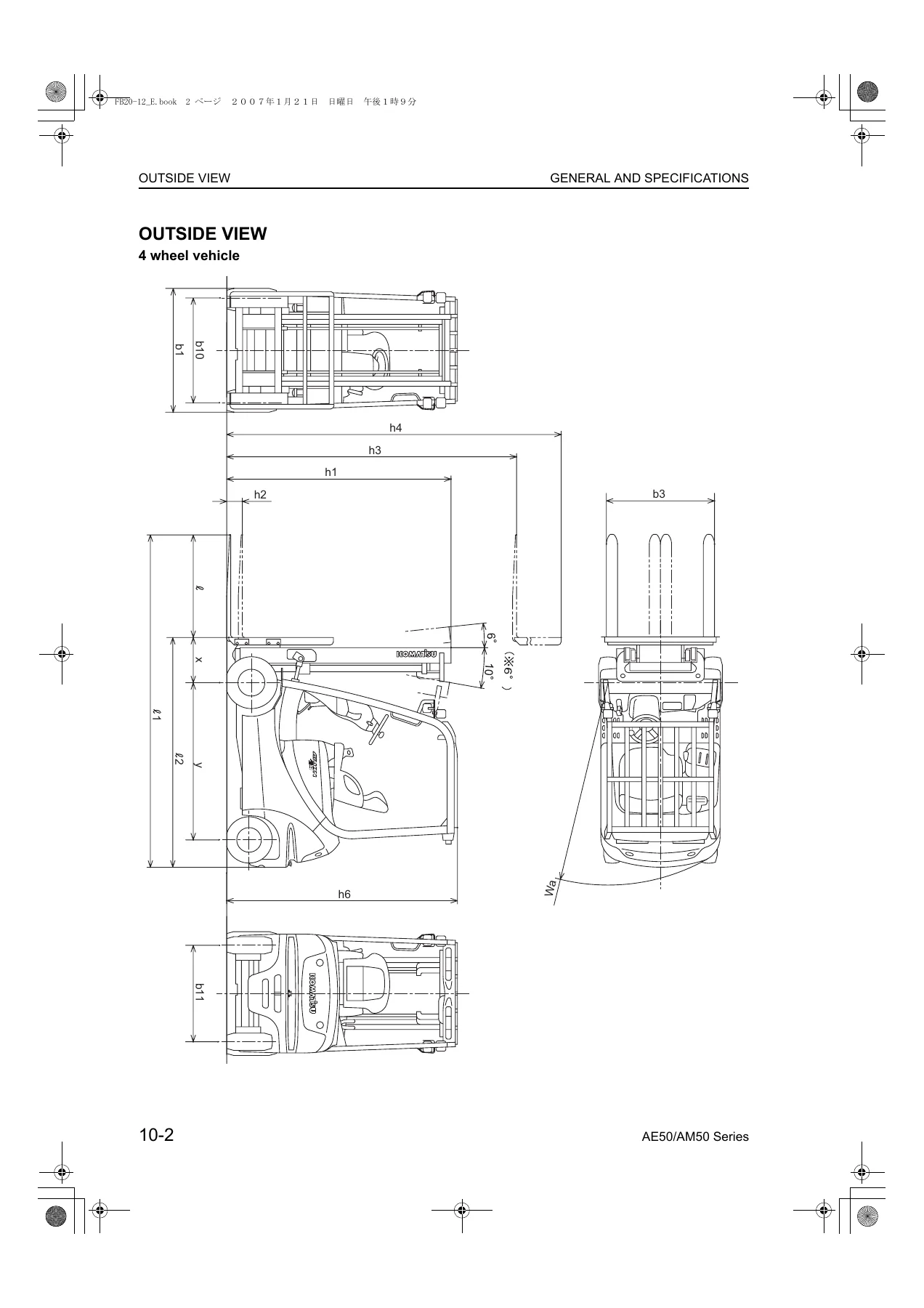
Outside-view drawings for both the four-wheel and three-wheel vehicles with all principal dimensions marked. Full specification tables cover rated capacity, load centre, service weight, axle loading, tire size and pressure, mast heights, free lift, travel and lift speeds, drawbar pull, gradeability, brake type, drive motor and pump motor ratings, battery voltage and capacity, and relief pressure settings for every model in the range. Periodic replacement intervals for consumable parts, standard tightening torques for bolts and pipe joints, and the correct procedure for applying LOCTITE are all included.
20. Testing and Adjusting
Contains the service data tables, the method of releasing hydraulic pressure before opening any pipework, the lift interrupt function, the meter panel layout and how to set date-time, hour meter, vehicle speed limit, travel and cargo handling power, and user-mode lift speed. Battery electrolyte level and specific gravity checks, fuse locations for both the controller block and the installation-type charger, transfer case oil level and replacement, vehicle-mounted and installation-type charger voltage tap selection, wet-type disc brake and parking brake adjustment, wheel brake check, hydraulic oil tank level and replacement, mast roller and shim adjustment, finger bar, naturally descending and naturally forward-tilting measurement, air bleeding for brake piping, lift cylinder and mast, plus the full list of lubricants and greases.
30. Removal and Installation
Unit location diagrams for both four-wheel and three-wheel vehicles, unit masses, and disassembly/assembly drawings for the mast, lift cylinder, drive axle, steering axle, rear axle, battery, hydraulic pump and pump motor, and vehicle-mounted charger. Each procedure gives the order of removal, the safety precautions, the tightening torque values, the wiring and sensor connector colours, and the adjustments needed on reassembly such as stabilizer projection and mast synchronization.
40. Disassembly and Assembly
Detailed overhaul procedures for the drive axle with wet-type multi-disc brake, the wheel cylinder, the brake master cylinder, the ORBITROL steering gear, the lift cylinder for both standard and high-lift masts, the tilt cylinder, the gear pump, the proportional solenoid control valve, and both the drive and pump AC motors. Judging standards give standard dimension and limit-allowed values for each wear item, and assembly notes specify LOCTITE grades, grease types, shim selection and press-fit torques.
50. Maintenance Standard
The judging standard tables for the brake in the drive axle, the wheel cylinder, the brake lever, the hydraulic pump, the mast and finger bar, and the lift and tilt cylinders. Clearance limits, disc and plate thickness limits, spring free lengths, bushing dimensions and interference values are all listed with the recommended remedy for each.
60. Structure and Function
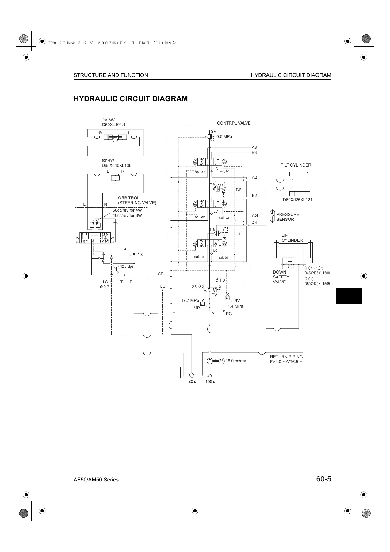
Explains how the brake system works under fluid pressure and under parking lever operation, the full hydraulic circuit diagram, and the internal function of the control valve including the main relief valve, load check valve, lift lock valve, tilt lock valve, proportional solenoid pressure reducing valve, pressure reducing valve, sequence valve, priority valve and port relief valve. Operation is described for neutral, lift ascent, lift descent, backward tilt, forward tilt, attachment operation, and for the lift lock and tilt lock valves in each state.
70. Troubleshooting
The full abnormal code list including ALA alarm codes and ERR error codes, plus diagnostic procedures for each code. Controller connector pin assignments with signal names and reference voltages for the travel R controller, travel L controller, cargo handling controller and proportional solenoid valve controller. Meter panel symptom-wise diagnosis covering over fifty faults. Sensor, coil, harness and voltage check procedures for the proportional solenoid valve controller, lift pressure sensor, lever sensors, and the meter panel. Also covers how to connect the PC service tool and the CAN communication converter.
80. Yearly Inspection Criteria
Inspection items for the motor, control equipment, charge control unit, battery, power transfer equipment, traveling equipment, steering equipment, braking equipment, cargo handling equipment, hydraulic equipment, body, safety equipment, and a total function test. Each item lists the check content, the criteria, and the remedy.
90. Conversion Table and Appendix
Millimetre-to-inch, cubic metre-to-cubic yard, litre-to-gallon, kilogram-to-pound, kg/cm2-to-lb/in2, kgm-to-ft.lb and temperature conversion tables. The appendix contains the special jig part numbers, the service tool configuration, and the electrical circuit diagram.
What This Komatsu Electric Forklift Shop Manual Lets You Do
With this manual on hand you can service, diagnose and rebuild the Komatsu AE50/AM50 Series electric forklift without waiting on a dealer. You can adjust the wet-type disc brake and parking brake to the exact lever operating force and clearance, set the lift interrupt and user-mode lift speed, choose the correct input tap on the charger transformer for the site voltage, measure the naturally descending and naturally slanting amounts of the hydraulic cylinders, and pick the right shim to synchronize the mast cylinders. You can read every abnormal code on the meter panel, work through the controller pin voltages, and identify whether the fault is in the lever sensor, the proportional solenoid valve, the harness or the controller itself. You can pull the drive axle, replace the wet-type multi-disc brake pack to the correct gap, set the hub rotational start-up torque, and refit the unit with the right tightening torques and sensor connector colours.
Every procedure in this Komatsu AE50/AM50 electric forklift shop manual is written for the technician working on the machine, not for a classroom. The testing and adjusting chapter gives you the values, the removal and installation chapter gives you the order, the disassembly and assembly chapter gives you the wear limits and the assembly lubricants, and the troubleshooting chapter gives you the diagnostic path when the truck will not move or the mast will not lift. Having the correct clearances, torques and pressures on screen while you work is the difference between a repair that lasts and a comeback job.
IMAGES PREVIEW
The PDF is delivered instantly after payment. There is no shipping, no waiting for a disc, and no need for a dedicated reader. Download it once and keep it on a laptop, tablet or phone in the workshop, or print only the pages you need for the job in front of you. Whether you are a fleet workshop, an independent forklift mechanic or an owner-operator maintaining a single truck, this Komatsu AE50/AM50 Series shop manual gives you the full factory service information for the FB10 through FB20 electric range in one file.
Reviews
There are no reviews yet.