Komatsu BULLDOZER D65EX -15E0 D65PX -15E0 D65WX-15E0 Shop Manual SEN00046-14 PDF
$36.95
Komatsu BULLDOZER D65EX -15E0 D65PX -15E0 D65WX-15E0 Shop Manual SEN00046-14 – PDF DOWNLOAD
SERIAL NUMBERS
D65EX- 69001
D65PX- 69001
D65WX-69001
and up
Description
Komatsu BULLDOZER D65EX -15E0 D65PX -15E0 D65WX-15E0 Shop Manual SEN00046-14 – PDF DOWNLOAD
FILE DETAILS:
Komatsu BULLDOZER D65EX -15E0 D65PX -15E0 D65WX-15E0 Shop Manual SEN00046-14 – PDF DOWNLOAD
Language : English
Pages :1252
Downloadable : Yes
File Type : PDF
DESCRIPTION:
Komatsu BULLDOZER D65EX -15E0 D65PX -15E0 D65WX-15E0 Shop Manual SEN00046-14 – PDF DOWNLOAD
SERIAL NUMBERS
D65EX- 69001
D65PX- 69001
D65WX-69001
and up
1. General precautions
Mistakes in operation are extremely dangerous. Read the Operation and Maintenance Manual carefully before operating the machine. In addition, read this manual and understand its contents before starting the work.
TABLE OF CONTENTS:
Komatsu BULLDOZER D65EX -15E0 D65PX -15E0 D65WX-15E0 Shop Manual SEN00046-14 – PDF DOWNLOAD
SERIAL NUMBERS
D65EX- 69001
D65PX- 69001
D65WX-69001
and up
SEN00046-14 3
00 Index and foreword 3
Index 3
Composition of shop manual 4
Table of contents1 6
Foreword and general information 17
Safety notice 18
How to read the shop manual 23
Explanation of terms for maintenance standard 25
Handling of electric equipment and hydraulic component 27
Handling of connectors newly used for engines 36
How to read electric wire code 39
Precautions when carrying out operation 42
Method of disassembling and connecting push-pull type coupler 45
Standard tightening torque table 48
Conversion table 52
01 Specification 59
Specification and technical data 59
Specification dimensions 60
Specifications 61
Weight table 66
Table of fuel, coolant and lubricants 68
10 Structure, function and maintenance standard 71
Engine and cooling system 71
Cooling system 72
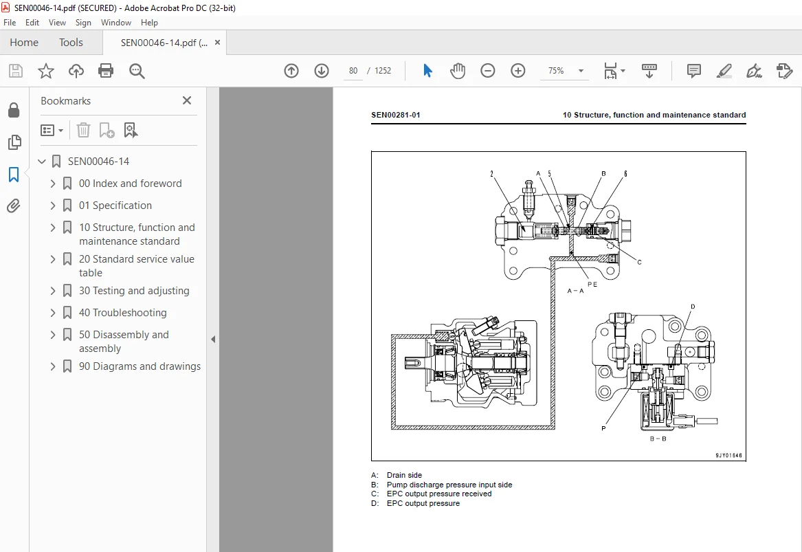
Cooling fan pump 74
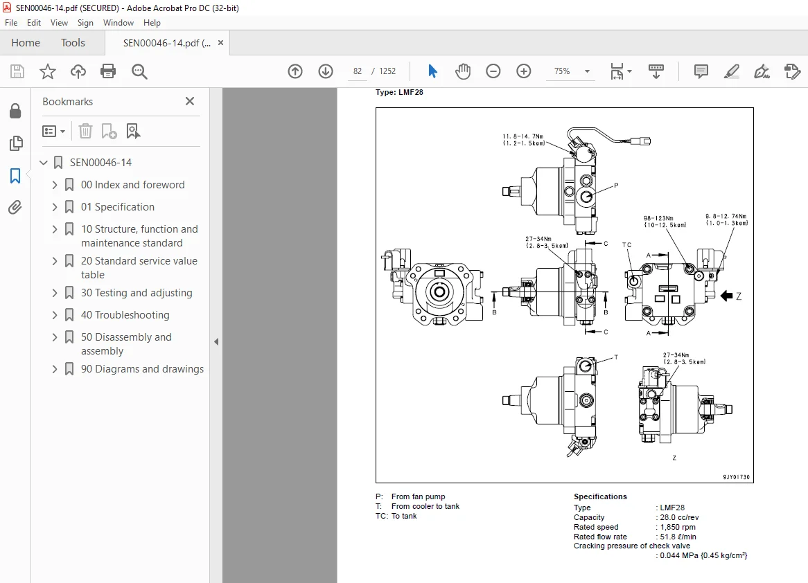
Cooling fan motor 82
Power train, Part 1 89
Power train 90
HSS system 92
General view of power train unit 94
Power train hydraulic piping drawing 96
Transmission, steering and brake control 98
Damper and universal joint 100
Torque converter and PTO 103
Transmission 108
Transmission clutch ECMV 124
Main relief valve and torque converter relief valve 130
Lubrication relief valve 132
Power train, Part 2 135
Bevel gear shaft, HSS and brake 136
Brake valve 158
Final drive 164
Undercarriage and frame 171
Main frame 172
Suspension 174
Track frame and idler cushion 180
Idler 184
Track roller 186
Carrier roller 190
Sprocket 192
Track shoe 196
Hydraulic system, Part 1 203
Work equipment hydraulic piping diagram 204
Work equipment control 206
Hydraulic tank and filter 208
Scavenging pump 210
Power train and steering lubrication pump 211
HSS pump 212
HSS motor 230
Hydraulic system, Part 2 239
Control valve 240
Self pressure reducing valve 274
Hydraulic system, Part 3 283
PPC valve (blade lift, blade tilt) 284
PPC valve (ripper) 290
Electric lever (steering) 294
Quick drop valve 298
PPC lock valve 300
Accumulator 301
Work equipment 303
Blade 304
Cutting edge and end bit 308
Ripper 309
Hydraulic cylinder 310
Piston valve 313
Cab and its attachments 315
Cab mount 316
Cab 317
Air conditioner 319
Electrical system 321
Monitor system 322
Monitor panel 324
Engine control 333
Engine control system 334
Cooling system control system 336
System components 338
Palm command control system 346
KOMTRAX system 348
Sensor 350
20 Standard service value table 355
Standard service value table 355
Standard service value table for engine 356
Standard service value table for chassis 358
30 Testing and adjusting 371
Testing and adjusting, Part 1 371
Tools for testing, adjusting, and troubleshooting 373
Measuring engine speed 376
Measuring intake air pressure (boost pressure) 378
Measuring exhaust temperature 380
Measuring exhaust gas color 382
Adjusting valve clearance 383
Measuring compression pressure 386
Measuring blow-by pressure 390
Measuring engine oil pressure 391
Handling of fuel system devices 392
Releasing residual pressure from fuel system 392
Testing fuel pressure 393
Testing fuel return and leak amount 398
Bleeding air from fuel circuit 400
Testing fuel circuit for leakage 401
Handling of reduced cylinder mode operation 402
Testing and adjusting air conditioner compressor belt tension 403
Adjusting fuel control dial and decelerator pedal 404
Measuring power train oil pressure 406
Adjusting transmission speed sensor (replacement procedure) 410
Simple method to test brake performance 411
Adjusting brake pedal 412
Adjusting parking brake lever 414
Emergency escape method when power train has trouble 415
Adjusting clearance of idler 418
Inspecting wear of sprocket 419
Testing and adjusting track shoe tension 419
Testing and adjusting work equipment and HSS oil pressure 420
Testing control circuit basic pressure 423
Measuring PPC valve output pressure 424
Adjusting work equipment PPC valve play 426
Measuring internal leakage of work equipment cylinder 428
Bleeding air from work equipment cylinder 428
Releasing residual pressure in work equipment cylinder 429
Checking parts which caused hydraulic drift of blade or ripper 430
Adjusting work equipment lock lever 431
Measuring fan motor speed 432
Measuring fan pump circuit pressure 433
Bleeding air from fan pump 434
Adjusting straight tiltdozer 435
Testing and adjusting operator cab 437
Testing and adjusting, Part 2 443
Special functions of monitor panel (EMMS) 444
Testing and adjusting, Part 3 487
Handling of voltage circuit of engine controller 488
Adjustment method when controller has been replaced 488
Preparation work for troubleshooting for electric system 490
Inspection procedure of diode 495
Pm-Clinic service 496
How to start operation of KOMTRAX terminal 506
Lamp display of KOMTRAX terminal 510
40 Troubleshooting 515
General information on troubleshooting 515
Points to remember when troubleshooting 516
How to proceed troubleshooting 517
Checks before troubleshooting 518
Classification and procedures of troubleshooting 519
How to distinguish wire code 522
Connection table for connector pin numbers 526
T- branch box and T- branch adapter table 562
Troubleshooting by failure code (Display of code), Part 1 567
Failure code table 569
Before troubleshooting by failure codes 576
Contents of troubleshooting table 578
Failure code [1500L0] Transmission clutch: Dual engagement 580
Failure code [15SAL1] Forward clutch: Fill signal is ON when command current is OFF 582
Failure code [15SALH] Forward clutch: Fill signal is OFF when command current is ON 584
Failure code [15SBL1] Reverse clutch: Fill signal is ON when command current is OFF 586
Failure code [15SBLH] Reverse clutch: Fill signal is OFF when command current is ON 588
Failure code [15SEL1] 1st clutch: Fill signal is ON when command current is OFF 590
Failure code [15SELH] 1st clutch: Fill signal is OFF when command current is ON 591
Failure code [15SFL1] 2nd clutch: Fill signal is ON when command current is OFF 592
Failure code [15SFLH] 2nd clutch: Fill signal is OFF when command current is ON 594
Failure code [15SGL1] 3rd clutch: Fill signal is ON when command current is OFF 596
Failure code [15SGLH] 3rd clutch: Fill signal is OFF when command current is ON 598
Failure code [AB00MA] Alternator: Malfunction 600
Failure code [B@BAZG] Engine oil: Oil pressure too low 600
Failure code [B@BCNS] Radiator coolant: Overheat 601
Failure code [B@CENS] Power train oil: Overheat 601
Failure code [B@HANS] Hydraulic oil: Overheat 602
Failure code [CA111] Engine controller: Abnormality in controller 603
Failure code [CA115] Abnormal engine Ne and Bkup speed sensors:Abnormal speed sensor signal 603
Failure code [CA122] Charge pressure sensor too high:Excessively high voltage detected 604
Failure code [CA123] Charge pressure sensor too low: Excessively low voltage detected 606
Failure code [CA131] Decelerator pedal sensor too high:Excessively high voltage detected 608
Failure code [CA132] Decelerator pedal sensor too low: Excessively low voltage detected 610
Failure code [CA144] Coolant temperature sensor too high:Excessively high voltage detected 612
Failure code [CA145] Coolant temperature sensor too low:Excessively low voltage detected 614
Failure code [CA153] Charge temperature sensor too high:Excessively high voltage detected 616
Failure code [CA154] Charge temperature sensor too low:Excessively low voltage detected 618
Failure code [CA155] Charge temperature too high and engine speed derated:Exceeded upper control limit of temperature 620
Failure code [CA187] Sensor power source 2 too low: Excessively low voltage detected 622
Failure code [CA221] Atmospheric pressure sensor too high:Excessively high voltage detected 624
Failure code [CA222] Atmospheric pressure sensor too low:Excessively low voltage detected 626
Failure code [CA227] Sensor power source 2 too high: Excessively high voltage detected 628
Failure code [CA234] Engine over speed: Excessively high speed 630
Failure code [CA238] Abnormal power source for Ne speed sensor:Excessively low voltage detected 631
Failure code [CA271] IMV/PCV1 short circuit: Short circuit 632
Failure code [CA272] IMV/PCV1 disconnection: Disconnection 634
Failure code [CA281] Abnormal supply pump pressure balance:Abnormal pressure feed of fuel 636
Troubleshooting by failure code (Display of code), Part 2 639
Failure code [CA322] Injector No 1 system disconnection or short circuit:disconnection, short circuit 642
Failure code [CA323] Injector No 5 system disconnection or short circuit:disconnection, short circuit 644
Failure code [CA324] Injector No 3 system disconnection or short circuit:disconnection, short circuit 646
Failure code [CA325] Injector No 6 system disconnection or short circuit:disconnection, short circuit 648
Failure code [CA331] Injector No 2 system disconnection or short circuit:disconnection, short circuit 650
Failure code [CA332] Injector No 4 system disconnection or short circuit:disconnection, short circuit 652
Failure code [CA342] Engine controller data matching error: matching error 654
Failure code [CA352] Sensor power source 1 too low: Excessively low voltage detected 656
Failure code [CA386] Sensor power source 1 too high: Excessively high voltage detected 658
Failure code [CA428] Water detection sensor too high: Excessively high voltage detected 660
Failure code [CA429] Water detection sensor too low: Excessively low voltage detected 662
Failure code [CA435] Abnormal engine oil pressure switch: Abnormal signal circuit 664
Failure code [CA441] Power source voltage too low: Excessively low voltage detected 666
Failure code [CA442] Power source voltage too high: Excessively high voltage has occurred in the controller power source circuit 668
Failure code [CA449] Common rail pressure too high (2):Excessively high pressure trouble occurred 670
Failure code [CA451] Common rail pressure sensor too high:Excessively high voltage detected 674
Failure code [CA452] Common rail pressure sensor too low:Excessively low voltage detected 676
Failure code [CA488] Charge temperature too high and torque derated:Exceeded upper control limit of temperature 678
Failure code [CA553] Common rail pressure too high (1):Excessively high pressure detected 679
Failure code [CA559] Loss of pressure feed from supply pump (1):Loss of pressure feed detected 680
Failure code [CA689] Abnormal engine Ne speed sensor: Abnormal signal 682
Failure code [CA731] Abnormal engine Bkup speed sensor phase: Abnormal phase 684
Failure code [CA757] Loss of all engine controller data: Loss of all data 686
Failure code [CA778] Abnormal engine Bkup speed sensor: Abnormal Bkup signal 688
Failure code [CA1633] Abnormal KOMNET: Abnormal communication 690
Failure code [CA2185] Decelerator pedal sensor power source too high:Excessively high voltage detected 692
Failure code [CA2186] Decelerator pedal sensor power source too low:Excessively low voltage detected 693
Failure code [CA2249] Loss of pressure feed from supply pump (2):Loss of pressure feed detected 694
Failure code [CA2265] Electric lift pump disconnection: Disconnection 696
Failure code [CA2266] Electric lift pump short circuit: Short circuit 698
Failure code [CA2311] Abnormal IMV solenoid: Abnormal resistance 700
Failure code [CA2555] Air intake heater relay disconnection: Disconnection 702
Failure code [CA2556] Air intake heater relay short circuit: Short circuit 704
Troubleshooting by failure code (Display of code), Part 3 707
Failure code [D110KA] Battery relay: Short circuit 710
Failure code [D110KB] Battery relay: Disconnection 712
Failure code [D130KA] Neutral safety relay: Disconnection 714
Failure code [D130KB] Neutral safety relay: Short circuit 716
Failure code [D161KA] Back-up alarm relay: Disconnection 718
Failure code [D161KB] Back-up alarm relay: Short circuit 720
Failure code [DAFRKR] Monitor panel CAN communication: Defective communication 722
Failure code [DAQ0KT] [DB30KT] Steering and transmission controller:Abnormality in controller 724
Failure code [DAQ1KK] [DB31KK] Main power source of steering and transmission controller: Power source voltage drop and input 726
Failure code [DAQ2KK] [DB32KK] Load power source of steering and transmission controller: Power source voltage drop and input 728
Failure code [DAQ5KK] [DB35KK] Steering and transmission controller sensor 5 V power source: Power source voltage drop and input 730
Failure code [DAQ6KK] [DB36KK] Steering and transmission controller sensor 24 V power source: Power source voltage drop and input 732
Failure code [DAQ9KQ] [DB39KQ] Steering and transmission controller model selection: Inconsistency in model select signal 734
Failure code [DB2RKR] Steering and transmission controller CAN communication: Defective communication 736
Failure code [DB30KT] [DAQ0KT] Steering and transmission controller: Abnormality in controller 738
Failure code [DB31KK] [DAQ1KK] Main power source of steering and transmission controller: Power source voltage drop and input 738
Failure code [DAB32KK] [DAQ2KK] Load power source of steering and transmission controller: Power source voltage drop and input 738
Failure code [DB35KK] [DAQ5KK] Steering and transmission controller sensor 5 V power source: Power source voltage drop and input 738
Failure code [DB36KK] [DAQ6KK] Steering and transmission controller sensor 24 V power source: Power source voltage drop and input 738
Failure code [DB39KQ] [DAQ9KQ] Steering and transmission controller model selection:Inconsistency in model select signal 738
Failure code [DD12KA] Shift up switch: Disconnection 740
Failure code [DD12KB] Shift up switch: Short circuit 742
Failure code [DD13KA] Shift down switch: Disconnection 744
Failure code [DD13KB] Shift down switch: Short circuit 746
Failure code [DD14KA] [DDQ2KA] Parking brake lever switch: Disconnection 748
Failure code [DD14KB] [DDQ2KB] Parking brake lever switch: Short circuit 750
Failure code [DDN7KA] Pitch control switch: Disconnection 752
Failure code [DDN7KB] Pitch control switch: Short circuit 754
Failure code [DDQ2KA] [DD14KA] Parking brake lever switch: Disconnection 756
Failure code [DDQ2KB] [DD14KB] Parking brake lever switch: Short circuit 756
Failure code [DGS1KX] Hydraulic oil temperature sensor:Input signal is out of normal range 758
Failure code [DGT1KA] Power train oil temperature sensor: Disconnection 760
Failure code [DGT1KX] Power train oil temperature sensor: Input signal is out of normal range 761
Failure code [DK10KA] Fuel dial: Disconnection 762
Failure code [DK10KB] Fuel dial: Short circuit 764
Failure code [DK30KA] Steering potentiometer (1): Disconnection 766
Failure code [DK30KB] Steering potentiometer (1): Short circuit 768
Failure code [DK30KX] Steering potentiometer: Input signal is out of normal range 770
Failure code [DK30KZ] Steering potentiometer: Disconnection or short circuit (Double failure) 771
Failure code [DK30L8] Steering potentiometer: Inconsistent analog signal 771
Failure code [DK31KA] Steering potentiometer (2): Disconnection 772
Failure code [DK31KB] Steering potentiometer (2): Short circuit 774
Failure code [DK40KA] Brake potentiometer: Disconnection 776
Failure code [DK40KB] Brake potentiometer: Short circuit 777
Failure code [DK55KX] Forward-reverse potentiometer: Input signal is out of normal range 778
Failure code [DK55KZ] Forward-reverse potentiometer:Disconnection or short circuit (Double failure) 779
Failure code [DK55L8] Forward-reverse potentiometer: Inconsistent analog signal 780
Failure code [DK56KA] Forward-reverse potentiometer (1): Short circuit 782
Failure code [DK56KB] Forward-reverse potentiometer (1): Disconnection 784
Failure code [DK57KA] Forward-reverse potentiometer (2): Disconnection 786
Failure code [DK57KB] Forward-reverse potentiometer (2): Short circuit 788
Troubleshooting by failure code (Display of code), Part 4 791
Failure code [DKH1KA] [DKH1KX] Pitch angle sensor: Short circuit 793
Failure code [DKH1KX], [DKH1KA] or [DKH1KB] Pitch angle sensor: Input signal out of range 795
Failure code [DLT3KA] Transmission output speed sensor: Disconnection 796
Failure code [DLT3KB] Transmission output speed sensor: Short circuit 797
Failure code [DV00KB] Alarm buzzer: Short circuit 798
Failure code [DW5AKA] Pitch control solenoid: Disconnection 799
Failure code [DW5AKB] Pitch control solenoid: Short circuit 800
Failure code [DW5AKY] Pitch control solenoid: Short circuit to power source line 801
Failure code [DW7BKA] Fan reverse solenoid: Disconnection 802
Failure code [DW7BKB] Fan reverse solenoid: Short circuit 803
Failure code [DWN1KA] HSS EPC solenoid right: Disconnection 804
Failure code [DWN1KB] HSS EPC solenoid right: Short circuit 805
Failure code [DWN1KY] HSS EPC solenoid right: Short circuit to power source line 806
Failure code [DWN2KA] HSS EPC solenoid left: Disconnection 807
Failure code [DWN2KB] HSS EPC solenoid left: Short circuit 808
Failure code [DWN2KY] HSS EPC solenoid left: Short circuit to power source line 809
Failure code [DWN5KA] Fan pump TVC solenoid: Disconnection 810
Failure code [DWN5KB] Fan pump TVC solenoid: Short circuit 811
Failure code [DWN5KY] Fan pump TVC solenoid: Short circuit in power source line 812
Failure code [DXA0KA] HSS pump TVC solenoid: Disconnection 813
Failure code [DXA0KB] HSS pump TVC solenoid: Short circuit 814
Failure code [DXA0KY] HSS pump TVC solenoid: Short circuit to power source line 815
Failure code [DXH4KA] 1st clutch ECMV: Disconnection 816
Failure code [DXH4KB] 1st clutch ECMV: Short circuit 817
Failure code [DXH4KY] 1st clutch ECMV: Short circuit to power source line 818
Failure code [DXH5KA] 2nd clutch ECMV: Disconnection 819
Failure code [DXH5KB] 2nd clutch ECMV: Short circuit 820
Failure code [DXH5KY] 2nd clutch ECMV: Short circuit to power source line 821
Failure code [DXH6KA] 3rd clutch ECMV: Disconnection 822
Failure code [DXH6KB] 3rd clutch ECMV: Short circuit 823
Failure code [DXH6KY] 3rd clutch ECMV: Short circuit to power source line 824
Failure code [DXH7KA] Reverse clutch ECMV: Disconnection 825
Failure code [DXH7KB] Reverse clutch ECMV: Short circuit 826
Failure code [DXH7KY] reverse clutch ECMV: Short circuit to power source line 827
Failure code [DXH8KA] Forward clutch ECMV: Disconnection 828
Failure code [DXH8KB] Forward clutch ECMV: Short circuit 829
Failure code [DXH8KY] forward clutch ECMV: Short circuit to power source line 830
Troubleshooting of electrical system (E-mode) 833
Contents of troubleshooting table 837
E-1 The engine does not start (the starting motor does not turn) 838
E-2 The preheater does not operate 842
E-3 The monitor panel does not light up at all when the starting switch is turned ON 846
E-4 When the starting switch is turned on, the monitor panel completely remains lighted and does not go out 847
E-5 While the engine is running, the battery charge level caution lamp flashes 848
E-6 While the engine is running, the emergency warning item flashes 850
E-7 While the preheater is operating, the preheating pilot lamp does not light up 854
E-8 The coolant temperature gauge does not indicate correctly 856
E-9 The power train oil temperature gauge does not indicate correctly 858
E-10 Hydraulic oil temperature gauge does not indicate properly 861
E-11 Fuel gauge does not indicate properly 864
E-12 Gear speed and engine speed are not indicated properly 865
E-13 The preset mode service meter does not indicate normally 865
E-14 The warning lamp does not flash or does not go out 865
E-15 The alarm buzzer does not sound or does not stop 866
E-16 Auto shift down is not possible or is not released 868
E-17 The buzzer cancel switch does not work 870
E-18 The information switch does not work 872
E-19 The fan cleaning does not operate or cannot be reset 874
E-20 The preset mode does not operate or cannot be reset 876
E-21 The monitor panel cannot be set in the service mode or cannot be set out of the service mode 878
E-22 The back-up alarm does not sound 880
E-23 The head lamp and rear lamp do not light up 882
E-24 The horn does not sound or does not stop 885
E-25 Malfunction of wipers 886
E-26 Washer does not spray water 902
E-27 The air conditioner does not operate 908
E-28 KOMTRAX system does not operate normally 912
Troubleshooting of hydraulic and mechanical system (H-mode) 915
Contents of troubleshooting table 917
H-1 There is no travel power (no drawbar pull) 918
H-2 Machine does not move (at 2nd or 3rd speed) 919
H-3 Machine does not move at any gear speed 920
H-4 Machine travels only in one direction, forward or in reverse 921
H-5 When gear is shifted or travel direction is changed, large time lag is made 922
H-6 Machine cannot be steered (Machine does not turn leftward or rightward) 923
H-7 Steering speed or power is low 923
H- 8 Brake does not work 924
H-9 Overheat of power train oil 925
H-10 Abnormal sound comes out from around HSS and work equipment pump or HSS motor 926
H-11 All work equipment speeds are slow 926
H-12 Work equipment does not move 927
H-13 Blade lift speed is slow or lacks power 927
H-14 Blade tilt speed is slow or lacks power 928
H-15 Ripper lift speed is slow or lacks power 928
H-16 Excessive hydraulic drift of blade lift 929
H-17 Excessive hydraulic drift of blade tilt 929
H-18 Excessive hydraulic drift of ripper lift 930
Troubleshooting of engine (S-mode) 933
Method of using troubleshooting charts 935
S-1 Starting performance is poor 938
S-2 Engine does not start 939
S-3 Engine does not pick up smoothly 942
S-4 Engine stops during operations 943
S-5 Engine does not rotate smoothly 944
S-6 Engine lacks output (or lacks power) 945
S-7 Exhaust smoke is black (imcomplete combustion) 946
S-8 Oil consumption is excessive (or exhaust smoke is blue) 947
S-9 Oil becomes contaminated quickly 948
S-10 Fuel consumption is excessive 949
S-11 Oil is in coolant (or coolant spurts back, or coolant level goes down) 950
S-12 Oil pressure drops 951
S-13 Oil level rises (water, fuel in oil) 952
S-14 Coolant temperature becomes too high (overheating) 953
S-15 Abnormal noise is made 954
S-16 Vibration is excessive 955
50 Disassembly and assembly 957
General information on disassembly and assembly 957
How to read this manual 958
Coating materials list 960
Special tool list 963
Sketches of special tools 969
Engine and cooling system, Part 1 979
Removal and installation of fuel supply pump assembly 980
Removal and installation of cylinder head assembly 984
Removal and installation of fuel injector assembly 999
Removal and installation of engine front oil seal1001
Removal and installation of engine rear oil seal1004
Engine and cooling system, Part 21011
Removal and installation of engine assembly1012
Removal and installation of radiator assembly1019
Removal and installation of air aftercooler assembly1023
Removal and installation of fan drive assembly1024
Removal and installation of fan motor assembly1025
Removal and installation of fuel tank assembly1026
Removal and installation of damper assembly1028
Removal and installation of engine hood assembly1029
Power train, Part 11031
Removal and installation of power train unit assembly1032
Disconnection and connection of power train unit assembly1035
Disassembly and assembly of PTO assembly1039
Disassembly and assembly of torque converter assembly1045
Disassembly and assembly of TORQFLOW transmission assembly1050
Power train, Part 21069
Disassembly and assembly of HSS assembly1070
Removal and installation of final drive assembly1088
Disassembly and assembly of final drive assembly1090
Undercarriage and frame, Part 11099
Removal and installation of track frame assembly1100
Removal and installation of idler assembly1102
Disassembly and assembly of idler assembly1103
Removal and installation of recoil spring assembly1107
Disassembly and assembly of recoil spring assembly1108
Removal and installation of track roller assembly1112
Disassembly and assembly of track roller assembly1113
Removal and installation of carrier roller assembly1117
Disassembly and assembly of carrier roller assembly1118
Undercarriage and frame, Part 21123
Expansion and installation of track shoe assembly (Conventional type track shoe)1124
Expansion and installation of track shoe assembly (PLUS type track shoe)1127
Whole disassembly and whole assembly of track shoe assembly (Conventional type track shoe)1128
Whole disassembly and whole assembly of track shoe assembly (PLUS type track shoe)1141
Field disassembly and assembly of one link (Conventional type track shoe)1154
Field disassembly and assembly of one link (PLUS type track shoe)1161
Removal and installation of pivot shaft assembly1166
Removal and installation of equalizer bar assembly1167
Disassembly and assembly of equalizer bar side bushing1169
Hydraulic system1171
Removal and installation of control valve assembly1172
Disassembly and assembly of control valve assembly1174
Removal and installation of HSS pump assembly1175
Removal and installation of power train and lubricating oil pump assembly1176
Removal and installation of cooling fan pump assembly1177
Removal and installation of scavenging pump assembly1179
Removal and installation of HSS motor assembly1180
Disassembly and assembly of hydraulic cylinder assembly1181
Work equipment1189
Removal and installation of blade assembly1190
Cab and its attachments1195
Removal and installation of ROPS guard1196
Removal and installation of operator’s cab assembly1197
Removal and installation of operator’s cab glass (Stuck glass)1203
Removal and installation of floor frame assembly1211
Electrical system1219
Removal and installation of engine controller1220
Removal and installation of steering and transmission controller assembly1222
Removal and installation of KOMTRAX terminal1223
90 Diagrams and drawings1225
Hydraulic diagrams and drawings1225
Power train hydraulic circuit diagram1226
Hydraulic circuit diagram1227
Electrical diagrams and drawings1231
Electrical circuit diagram1233
Connector list and stereogram1249
IMAGES PREVIEW OF THE MANUAL:
S.M 26/12/24