
Komatsu CX50 Series Forklift Shop Manual – FG40/FD40/50A Series PDF Repair Guide
Original price was: $39.95.$23.95Current price is: $23.95.
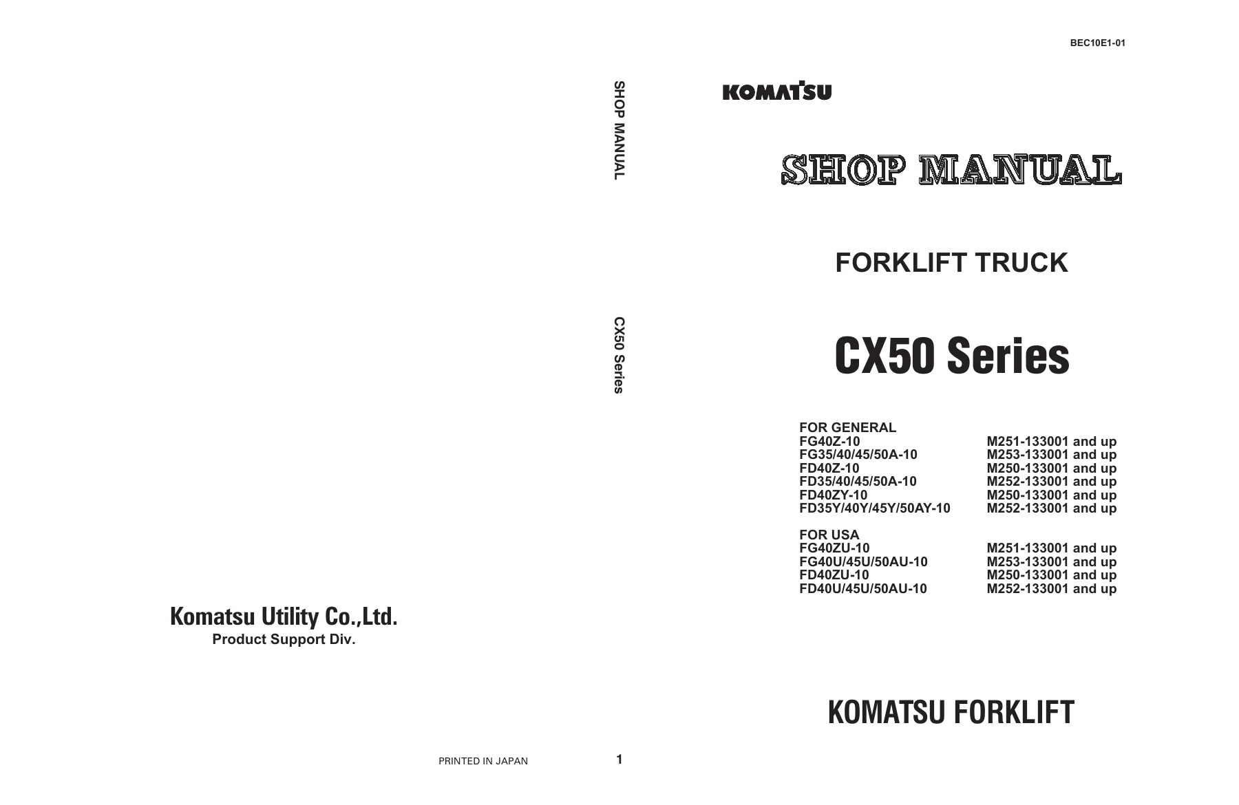
Complete Komatsu CX50 Series forklift shop manual covering FG40Z, FG35/40/45/50A, FD40Z, FD35/40/45/50A, FD40ZY and FD35Y/40Y/45Y/50AY-10 models. 754-page PDF with engine, power train, steering, brake, hydraulic and electrical service procedures.
Description
Komatsu CX50 Series Forklift Shop Manual – FG40/FD40/50A Series PDF Repair Guide
This Komatsu CX50 Series Forklift Shop Manual is the complete workshop reference for FG40Z-10, FG35/40/45/50A-10, FD40Z-10, FD35/40/45/50A-10, FD40ZY-10 and FD35Y/40Y/45Y/50AY-10 forklift trucks, plus the USA-market FG40ZU-10, FG40U/45U/50AU-10, FD40ZU-10 and FD40U/45U/50AU-10 variants. Published under Form No. BEC10E1-01 by Komatsu Utility Co., Ltd. Product Support Div., it runs 754 pages covering structure, function, maintenance standards, testing, adjusting, troubleshooting, disassembly and assembly across every major system on these machines.
File Details
- Manual type: Forklift Shop Manual (workshop service and repair reference)
- Brand: Komatsu / Komatsu Utility
- Series: CX50 Series
- Form number: BEC10E1-01
- Language: English
- Page count: 754 pages
- File format: PDF
- Serial applicability: M251-133001 and up, M253-133001 and up, M250-133001 and up, M252-133001 and up
- Engine coverage: SAA4D95LE-5-A, S4D95LE-3, EBT-TB45-1A/2A/3A
Chapters Covered
- 00 Index and Foreword – Index, safety notice, how to read the shop manual, maintenance standard terminology, electric and hydraulic handling, engine connector handling, wire code reading, standard tightening torque tables, conversion tables
- 01 Outline – Specification dimension drawings, weight tables, lubricant lists
- 10 Structure, Function and Maintenance Standard
- Engine and cooling system – radiator, brake oil cooler, torque converter oil cooler, aftercooler
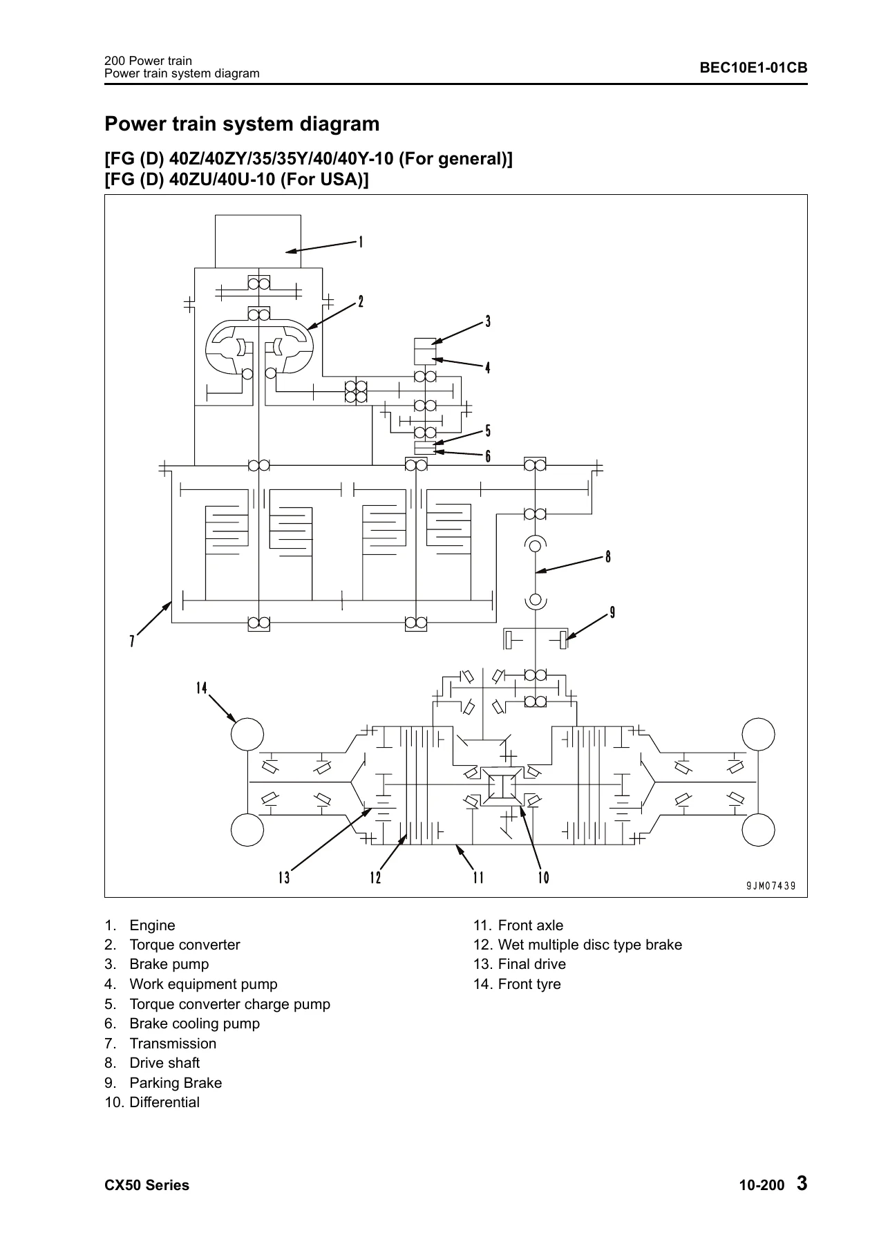
- Power train – torque converter, transmission, transmission control valve, relief valve, drive shaft, front axle, differential, final drive
- Steering system – steering piping, orbit-roll valve, power steering cylinder, EPACS
- Brake system – brake control, service brake, accumulator charge valve, brake valve, slack adjuster, accumulator, parking brake
- Undercarriage and frame – rear axle, hydraulic tank piping
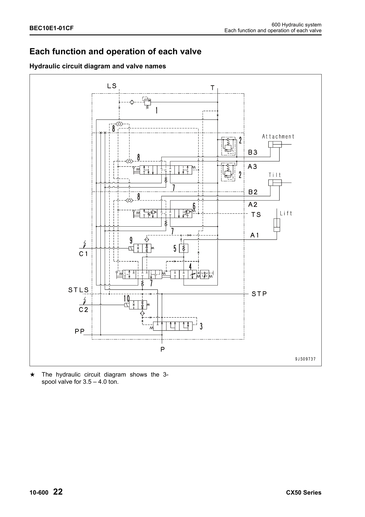
- Hydraulic system – control valve piping, work equipment piping, attachment piping, work equipment and steering pump (LPV45), control valve, CLSS, valve functions
- Work equipment – tilt cylinder, lift cylinder, mast, fork carriage, fork
- Electric devices Part 1 – accelerator pedal sensor, ISO controller (OPS), EPACS controller, instrument panel, engine starting and stopping circuits, wiring diagram
- Electric devices Part 2 – sensors, switches, lamps, horn, buzzer, flasher, F/R and F2 solenoid valves, relay box, resistor, diode, fuse, battery
- 20 Standard Value Table – complete standard value and judgement criteria tables for all models and engines
- 30 Testing and Adjusting – troubleshooting software, hydraulic pressure release, engine oil and filter service, fuel filter, radiator cleaning, air cleaner, differential oil, TORQFLOW transmission service, power train oil pressure testing, hydraulic tank, brake disc wear, parking brake, air bleeding, pedal adjustments, orbit-roll initialization, mast and carriage adjustment, drive shaft checks, diode testing
- 40 Troubleshooting
- General troubleshooting information and fuse locations
- Failure code troubleshooting (ISO controller system) Parts 1 and 2
- Failure code troubleshooting (EPACS controller system) Part 3
- Electrical system E-mode troubleshooting Parts 1-5
- Hydraulic and mechanical system H-mode troubleshooting (H-1 through H-55)
- 50 Disassembly and Assembly – general information, special tools, LOCTITE usage, power train removal, front axle, transmission, torque converter, drive shaft, differential, axle housing, parking brake, rear axle, power steering cylinder, brake pedal, brake valve, steering valve, control valve, lift cylinder, tilt cylinder, mast
- 80 Yearly Inspection Criteria – complete yearly inspection checklist covering 85 inspection items
- 90 Diagrams and Drawings – hydraulic circuit diagrams and electrical diagrams and drawings for all engine variants
What this shop manual gives a technician is the full factory-level procedure set behind every repair on the CX50 Series. The structure, function and maintenance standard chapter explains how each major assembly works and supplies the standard sizes, tolerances, clearances, interference limits and repair limits needed to decide whether a part is serviceable or must be replaced. The testing and adjusting chapter then supplies the measurement methods, tester specifications, oil pressure pickup port locations and adjustment procedures to verify the machine after service. The troubleshooting section is unusually thorough: ISO controller failure codes, EPACS controller failure codes, electrical system E-mode diagnostics across 5 volumes, and a 55-item hydraulic and mechanical H-mode chart that cross-references failure symptoms to probable causes across the power train, steering, brake and work equipment systems.
Model Coverage
Coverage is split between the general-market and USA-market CX50 Series forklifts, with separate standard value tables, wiring diagrams and troubleshooting procedures for each engine variant. General-market models are FG40Z-10, FG35-10, FG40-10, FG45-10, FG50A-10 (gasoline, engine EBT-TB45-1A/2A/3A) and FD40Z-10, FD35-10, FD40-10, FD45-10, FD50A-10 (diesel, engine SAA4D95LE-5-A), plus the Y-suffix variants FD40ZY-10, FD35Y-10, FD40Y-10, FD45Y-10, FD50AY-10 (diesel, engine S4D95LE-3). USA models are FG40ZU-10, FG40U-10, FG45U-10, FG50AU-10 and FD40ZU-10, FD40U-10, FD45U-10, FD50AU-10.
Systems and Procedures Included
The Komatsu CX50 Series forklift repair manual walks through the diesel and gasoline engine cooling systems, torque converter and TORQFLOW transmission, front and rear axles, differential and final drive, orbit-roll steering with optional EPACS electronic proportional active control steering, service brake and accumulator charge system, parking brake, and the complete hydraulic system including the LPV45 work equipment and steering pump, CLSS closed center load sensing control, priority valve, down control valve, lift lock and tilt lock functions, and emergency lowering valve.
Electrical content covers the ISO controller Operator Presence Sensing system (travel interlock, lift interlock, parking brake reminder, trouble detection), EPACS controller initialization and failure indication, instrument panel, engine starting and stopping circuits, relay box layout, fuse box connections, slow blow fuse locations, diode testing, and full electrical system wiring diagrams for each engine option.
Why This Manual Matters for CX50 Series Service
Komatsu CX50 Series forklifts are electronically governed machines with closed-center load sensing hydraulics, wet multiple disc brakes, electronically controlled fuel injection on the diesel variants, and an optional active steering correction system. Working on any of these systems without the factory standard values, oil pressure specifications, tightening torques and diagnostic trees is risky and slow. This shop manual provides the actual figures and the correct diagnostic sequence: for example, the TORQFLOW transmission main relief pressure is 1.13 ± 0.12 MPa {11.5 ± 1.2 kgf/cm2}, clutch operating pressure is 1.12 – 1.25 MPa {11.4 – 12.7 kgf/cm2}, and torque converter inlet oil pressure is 0.5 – 0.7 MPa {5 – 7 kgf/cm2}. The hydraulic system relief pressure is 20.6 MPa {210 kgf/cm2}. Lift cylinder hydraulic drift is limited to 50 mm/15 min and tilt cylinder hydraulic forward drift to 45 mm/15 min. These are the numbers that tell you whether a machine is in specification or needs repair.
Disassembly, Assembly and Torque Data
The disassembly and assembly chapter uses Komatsu’s standard symbol set (safety, caution, weight, tightening torque, coat, oil/coolant, drain) so each step shows the torque value, adhesive or sealant required, and any special tool needed. The special tool list includes clutch pack return spring compressor (3EC-97-99001), clutch pack piston insertion tool (3EC-97-99030), transmission output shaft bearing and oil seal driver (3EC-97-99110), bearing driver (3EC-97-99210), rear wheel and rim jointing bolt tool (3BA-97-13310), F and R shaft bearing driver (3EC-97-99190), drive axle side jig A (3EB-97-99340), transmission side jig B (3EB-97-99350), gasoline engine jig C (3EB-97-99360), diesel engine jig C (3EC-97-99130), and multiple oil seal driving jigs. A dedicated LOCTITE usage procedure explains degreasing, air drying, application methods, assembly and removal for threaded and fitting parts.
Yearly Inspection Criteria
The yearly inspection chapter is built as a complete 85-item checklist covering the prime mover (engine startability, idling speed, air cleaner, cylinder head, valve clearance, compression pressure, turbocharger, engine mount, lubrication, fuel system, high-pressure fuel gas system, blow-by device, coolant and radiator, fan and belt, ignition plug and timing, charger wiring), power train (transmission, torque converter, drive shaft, differential, final drive), traveling equipment (front axle, rear axle, tyres, wheels), steering system, brake system, loading equipment (fork, mast, fork carriage, lift chain, chain wheel, attachments), hydraulic equipment (tank and filter, piping, hydraulic pump, lift and tilt cylinders, control valve, solenoid valve, hydraulic drift) and lift truck body and safety devices.
Get Instant Access
This Komatsu CX50 Series Forklift Shop Manual PDF is delivered immediately after payment, with no shipping and no waiting. The file works on any device that reads PDF – laptop, desktop, tablet or phone – and every page can be printed for use in the workshop. Having the complete Komatsu CX50 Series forklift service manual on hand means a technician can run the correct diagnostic sequence for ISO controller or EPACS controller failure codes, look up the standard value for any wear part, follow the disassembly and assembly procedure with the correct torque, and complete the yearly inspection criteria without needing to guess or work from memory. For anyone maintaining FG40Z, FG35/40/45/50A, FD40Z, FD35/40/45/50A, FD40ZY or FD35Y/40Y/45Y/50AY-10 forklifts, this is the reference that keeps the machine in specification.
IMAGES PREVIEW
Reviews
There are no reviews yet.