
Komatsu D155AX-5 Shop Manual – Crawler Dozer Service Repair Manual PDF
Original price was: $44.95.$27.95Current price is: $27.95.
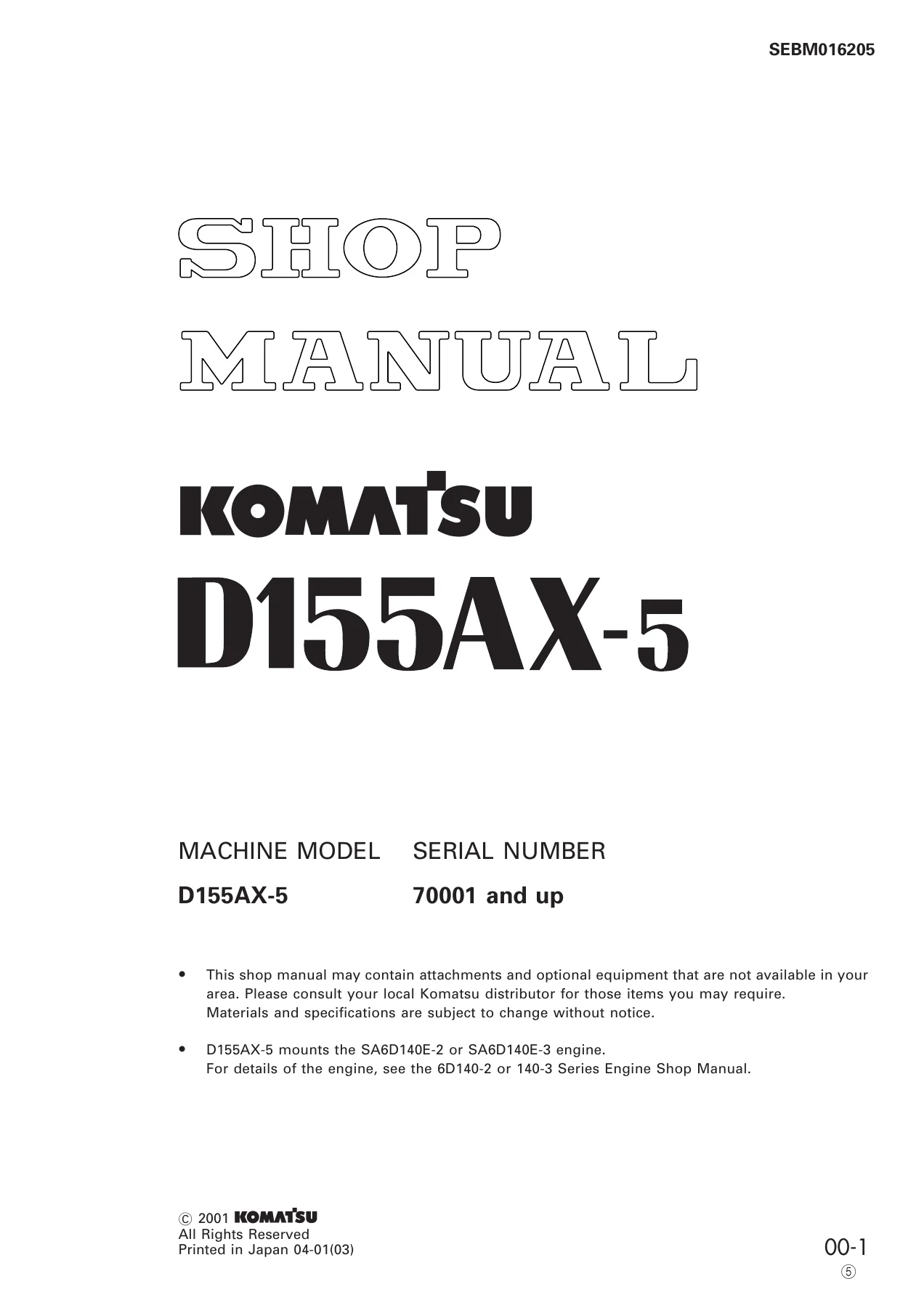
Complete Komatsu D155AX-5 shop manual covering serial number 70001 and up. Includes engine, power train, HSS system, undercarriage, hydraulics, troubleshooting, testing and adjusting, disassembly and assembly, and maintenance standards. Instant PDF download.
Description
Komatsu D155AX-5 Shop Manual – Complete Service and Repair Documentation
The Komatsu D155AX-5 Shop Manual is the comprehensive service and repair manual for the D155AX-5 crawler dozer, covering machines from serial number 70001 and up. This manual provides the technical information needed to service, diagnose, repair, and maintain the D155AX-5, and follows the same chapter structure used by Komatsu service technicians. Whether you are performing routine maintenance, troubleshooting a fault, or undertaking a major overhaul, this D155AX-5 service manual gives you the procedures, specifications, and standards required to get the job done correctly.
File Details
- Manual type: Shop Manual (Service Repair Manual)
- Brand: Komatsu
- Model: D155AX-5
- Serial number: 70001 and up
- Language: English
- File format: PDF
- Document number: SEBD0016205
- Page count: 1,000+ pages
Chapters Covered
This D155AX-5 repair manual is divided into the following major sections, each covering a distinct area of the machine:
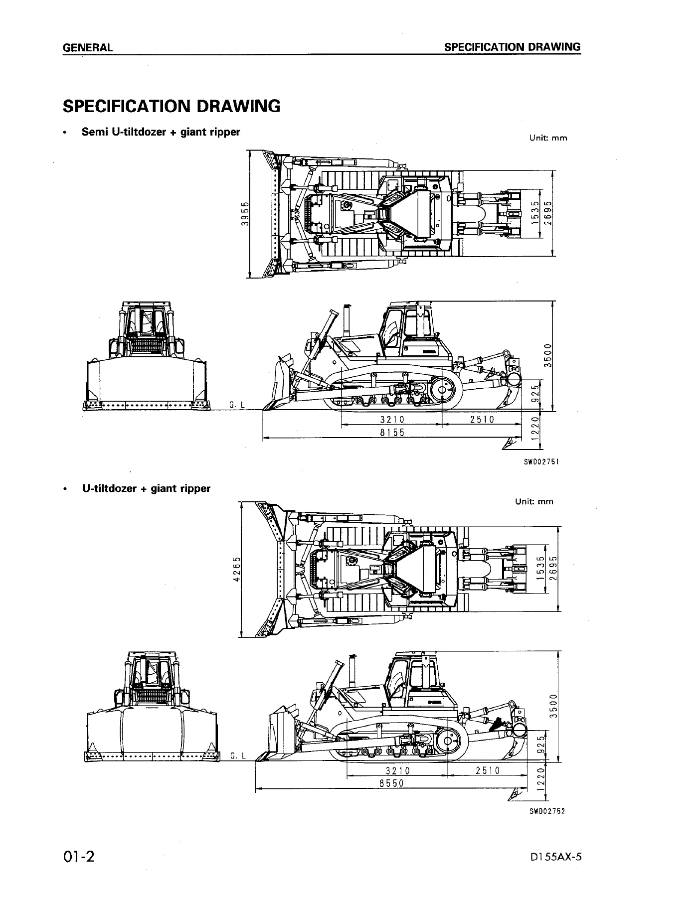
- 01 General – Specification drawing, Specifications, Weight table, Table of fuel, coolant and lubricants
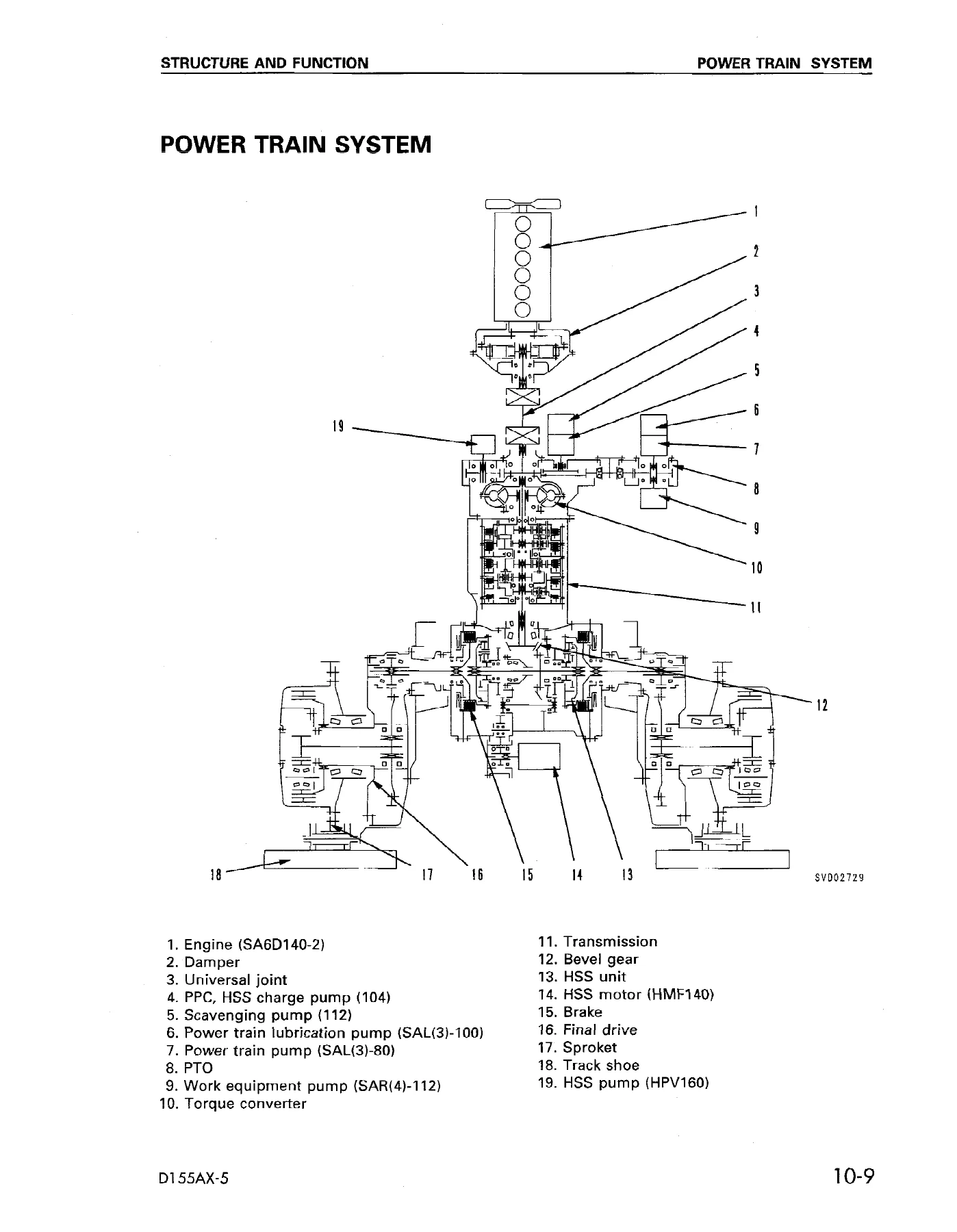
- 10 Structure and Function – Engine control, Radiator and oil cooler, Power train, Power train system, Overall drawing of power train unit, Power train hydraulic system, Damper universal joint, Torque converter and PTO, Transmission control, Transmission, Transmission control valve, Main relief valve, Lubricant relief valve, Scavenging pump strainer, Power train pump strainer, Power train oil filter, HSS system, HSS pump, HSS motor, PPC and HSS charge filter, PPC and HSS charge valve, HSS oil cooler bypass valve, Steering and brake control, Bevel gear shaft and HSS brake, Brake valve, Final drive, Track frame, Recoil spring, Track roller bogie, Main frame, Suspension, Work equipment hydraulic piping, PPC control piping, Work equipment control, Work equipment hydraulic system and HSS system, Hydraulic tank and filter, Accumulator, PPC lock valve, PPC valve, Piston valve, Pin puller switch, Pin puller solenoid valve, Tilt/Pitch selector switch, Pitch solenoid valve, Main control valve, Cylinder stay, Work equipment, Cap, Air conditioner, Electric wiring diagram, Electric circuit diagram, Monitor system, Sensors, Engine starting system, HSS electronic control system
- 20 Testing and Adjusting – Standard value tables for engine, chassis, and electrical parts; Tools for testing, adjusting, and troubleshooting; Measuring engine speed; Measuring intake air pressure; Measuring exhaust temperature; Measuring exhaust color; Adjusting valve clearance; Measuring compression pressure; Measuring blow-by pressure; Measuring engine oil pressure; Testing and adjusting fuel injection timing; Handling equipment in fuel circuit; Testing and adjusting alternator belt tension; Testing and adjusting air conditioner compressor belt tension; Testing and adjusting fan belt tension; Adjusting engine speed sensor; Handling controller high voltage circuit; Adjusting fuel control lever and decelerator pedal; Measuring torque converter stall speed; Measuring full stall speed; Measuring power train oil pressure; Testing and adjusting HSS main oil pressure; Testing and adjusting HSS charge oil pressure; Testing and adjusting HSS servo charge pressure and PPC relief pressure; Bleeding air from HSS pump; Simple procedure for testing brake performance; Adjusting joystick and parking lever; Testing and adjusting travel reverse sensing potentiometer; Adjusting travel reverse limit switch; Adjusting steering neutral position; Procedure for operating emergency steering switch; Adjusting initial current in HSS steering system; Adjusting brake pedal; Adjusting clearance of idler; Testing wear of sprocket; Testing and adjusting track shoe tension; Testing and adjusting hydraulic pressure; Measuring PPC valve output pressure; Adjusting play of PPC valve; Measuring solenoid valve output pressure; Testing location causing hydraulic drift of blade and ripper; Measuring leakage inside hydraulic cylinder; Releasing remaining oil pressure in hydraulic cylinder; Bleeding air from hydraulic cylinder; Adjusting work equipment safety lever; Adjusting semi-U tiltdozer; Troubleshooting
- 30 Disassembly and Assembly – Starting motor, Alternator, Engine oil cooler core, Fuel injection pump, Water pump, Turbocharger, Nozzle holder, Fuel injector, Engine front seal, Engine rear seal, Cylinder head, Thermostat, Air conditioner compressor, Air conditioner condenser, Fuel tank, Radiator, Radiator oil cooler guard, Fan drive, Hydraulic cooler, Engine, Damper, Power train unit, PTO, Torque converter, Torqflow transmission, HSS case, Hydraulic pump, HSS pump, HSS motor, Power train main relief valve, HSS and PPC charge valve, Transmission control valve, Brake valve, Final drive, Track frame, Idler assembly, Recoil spring, Track roller, Bogie, Carrier roller, Track shoe, Pivot shaft, Equalizer bar, Equalizer bar side bushing, Segment teeth, Hydraulic tank, Main control valve, HSS oil cooler bypass valve, Blade PPC valve, Ripper PPC valve, Blade lift cylinder, Blade tilt cylinder, Ripper lift cylinder, Ripper tilt cylinder, Hydraulic cylinder, Blade, Multi-shank ripper, ROPS guard, Operator cab, Hood, Floor frame, Dashboard, Monitor, HSS controller
- 40 Maintenance Standard – Engine mount, Power train unit mount, Damper and universal joint, Torque converter and PTO, Transmission, Transmission control valve, Main relief valve, Bevel gear shaft and HSS brake, Brake valve, Scavenging pump and PPC/HSS charge pump, Power train pump and lubrication pump, PPC/HSS charge valve, Oil cooler bypass valve, Final drive, Main frame, Track frame, Recoil spring, Track roller bogie, Idler, Track roller, Carrier roller, Track shoe, Suspension, Work equipment pump, HSS pump, HSS motor, PPC valve, Steering lever, Main control valve, Work equipment cylinder, Quick drop valve, Cylinder stay, Work equipment
- 90 Others – Work equipment hydraulic circuit and HSS circuit diagram, Electric circuit diagrams for serial numbers 70001-75000 and 75001 and up, Electric circuit diagram inside cab
This D155AX-5 workshop manual goes far beyond a simple owner’s handbook. It is a full workshop-level service publication that documents the structure and function of every major system on the machine, provides the testing and adjusting procedures needed to verify performance and correct faults, and supplies the maintenance standards required to judge wear and decide on repairs. The troubleshooting section alone spans engine, hydraulic, mechanical, electrical, and network systems, with judgment tables and flow charts that help you pinpoint the cause of a problem before disassembling components.
What This D155AX-5 Shop Manual Covers in Practice
For the engine, the manual covers the SA6D140E-2 and SA6D140E-3 engines used in the D155AX-5, with testing and adjusting procedures for engine speed, intake air pressure, exhaust temperature, exhaust color, valve clearance, compression pressure, blow-by pressure, engine oil pressure, and fuel injection timing. The fuel system section includes handling equipment in the fuel circuit, releasing remaining pressure, measuring fuel pressure, reduced cylinder mode operation, bleeding air from the fuel system, and checking for leakage in the fuel system.
The power train section covers the torque converter, PTO, transmission, transmission control valve, main relief valve, and HSS (Hydrostatic Steering System). Testing and adjusting procedures include torque converter stall speed, full stall speed, power train oil pressure, transmission main relief pressure, transmission modulating pressure, and brake oil pressure. The HSS system has its own dedicated testing and adjusting procedures for main oil pressure, charge oil pressure, servo charge pressure, PPC relief pressure, bleeding air from the HSS pump, and steering neutral position adjustment.
The undercarriage section covers the final drive, track frame, idler, recoil spring, track roller, bogie, carrier roller, track shoe, pivot shaft, equalizer bar, and segment teeth. Testing and adjusting procedures include idler clearance, sprocket wear, and track shoe tension. The work equipment section covers the hydraulic tank, main control valve, PPC valves, cylinders, quick drop valve, blade, and ripper, with procedures for measuring PPC valve output pressure, adjusting PPC valve play, measuring solenoid valve output pressure, testing hydraulic drift, measuring leakage inside hydraulic cylinders, releasing remaining oil pressure, bleeding air from hydraulic cylinders, and adjusting the semi-U tiltdozer.
The electrical section covers the electric wiring diagram, electric circuit diagram, monitor system, sensors, engine starting system, and HSS electronic control system. Troubleshooting covers the network system (N mode), engine system (S mode), HSS controller and electrical system (E mode), hydraulic and mechanical system (H mode), monitor system (M mode), engine controller system (G mode), and HSS controller and electrical system for later serial numbers.
Why the Komatsu D155AX-5 Repair Manual Matters
The D155AX-5 is a large crawler dozer used in heavy earthmoving, mining, and construction applications. When a machine of this size goes down, the cost of downtime is significant, and incorrect repairs can lead to repeat failures or damage to other components. Having the correct specifications, tightening torques, wear limits, and diagnostic procedures on hand is essential for efficient and reliable repair work. This D155AX-5 service repair manual provides that information in a single document, organized the same way the machine is built.
Because the manual covers serial number 70001 and up, it applies to a wide range of D155AX-5 machines, including both the SA6D140E-2 and SA6D140E-3 engine variants. The maintenance standards chapter gives the criteria for judging whether parts can be reused, repaired, or must be replaced, which is particularly valuable when working on undercarriage components and hydraulic systems where wear limits determine the cost of a repair.
The troubleshooting section is structured to help you work from symptoms to causes without unnecessary disassembly. The judgment tables let you see at a glance whether a problem is likely to be in the engine system, hydraulic and mechanical system, or electrical system, and then direct you to the appropriate troubleshooting code. For technicians who work on D155AX-5 machines regularly, this manual is the reference that makes accurate diagnosis possible.
IMAGES PREVIEW
Instant PDF Delivery
This Komatsu D155AX-5 shop manual is delivered as an instant PDF download. There is no shipping, no waiting for a physical book, and no risk of a damaged or lost package. The PDF can be viewed on any device that supports PDF files, including laptops, tablets, and smartphones, and it can be printed if you prefer a paper copy for the workshop. The file is fully text-searchable, so you can quickly find the section, specification, or procedure you need. Whether you are a professional technician, a fleet maintenance manager, or an owner-operator who does your own repairs, this D155AX-5 service manual gives you the information required to service and repair the machine correctly. Add it to your library today and have the complete workshop documentation for the D155AX-5 available whenever you need it.
Reviews
There are no reviews yet.