
Doosan DX490LC-7 & DX530LC-7 Excavator Shop Manual PDF – Serial 10001 & Up
Original price was: $44.95.$27.95Current price is: $27.95.
Complete Doosan DX490LC-7 and DX530LC-7 Excavator Shop Manual (document 950106-02204E) for serial number 10001 and up. Covers engine, hydraulics, electrical systems, removal and installation, troubleshooting, error codes, and full hydraulic/electrical schematics in one 673-page PDF.
Description
Doosan DX490LC-7 & DX530LC-7 Excavator Shop Manual (950106-02204E)
This Doosan DX490LC-7 and DX530LC-7 Excavator Shop Manual is the service reference document for the DX490LC-7 and DX530LC-7 tracked excavators starting at serial number 10001 and up. It is delivered as the complete PDF (document number 950106-02204E) and gathers safety, specifications, general maintenance, engine, hydraulic systems, electrical systems, removal and installation procedures, troubleshooting, wiring harness layout, error codes, and the hydraulic and electrical schematics into a single file. If you own, service, or maintain a DX490LC-7 or DX530LC-7 excavator, this shop manual gives you the procedures and reference values to work from in the field or the workshop.
File Details
- Manual type: Shop Manual
- Brand: Doosan
- Models covered: DX490LC-7, DX530LC-7 Excavator
- Serial number coverage: 10001 and Up
- Document number: 950106-02204E
- Language: English
- Page count: 673 pages
- File format: PDF (instant download, printable)
Chapters Covered
- Safety – Track Excavator Maintenance Safety, general safety instructions, long term storage, environment and circumstances
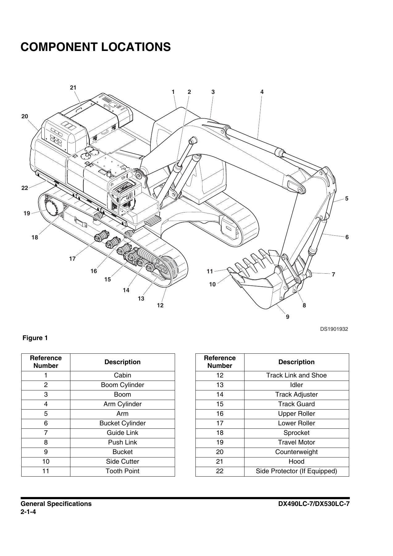
- Specifications – General specifications, component locations, overall dimensions, variable track and fixed track, standard specification, performance tests
- Engine specifications – engine performance curves, tightening torques
- Hydraulic systems and structure specifications – main pump, pilot pump, main control valve, remote control valves, fan drive, swing mechanism, travel system, undercarriage, front link pin sizes, cylinder
- General maintenance – welding precautions, hydraulic system precautions, cleanliness and oil leaks, cleaning and inspection, bearing inspection
- Standard torques – metric and U.S. fastener torque values, hose clamps, ORFS swivel nut torque, split flanges, torque wrench extension tools, tightening torque specifications
- Engine – valve clearance, cleaning, mechanical system (camshaft, connecting rod, crankshaft, piston, power take-off, torsion damper, V-belt, balance shaft, timing gear), fuel system, high pressure pump, injection system, lubricating system, cooling system, intake and exhaust system, VGT turbo charger, engine control and electrical system, aftertreatment system
- Hydraulic systems and components – systems operation, description and inspection; main oil circuit, pilot oil circuit, return and drain circuit, main system operations, pilot system operations
- Hydraulic components – main pump, angle sensor, main control valve, swing device, fan pump, fan motor, joystick valve, travel control valve, solenoid valve, EPPR valve, center joint, travel device
- Electrical systems – systems operation and description, fuse box, wiring connection, power supply, starting system, charging system, AVM system, gauge panel system, EPOS system, CAN communication, TMS, wiper system, joystick multi-function
- Removal and installation – Engine (ECU, V-belt, alternator, starter motor, DEF quality sensor, aftertreatment sensors, engine assembly); Hydraulic systems (main pump, drive coupling, undercovers, hydraulic oil tank, fuel tank, swing device, fan pump, oil cooler fan motor, joystick valve, travel control valve, center joint, travel device, main control valve, cabin); Electric and electronic (battery, EPOS controller, TMS controller, AVM controller, microphone controller, smart key controller, wiper controller, DC-DC controller, cabin switches, AVM, display monitor, hour meter, wiper motor)
- Troubleshooting – wiring harness layout (main harness, cabin harness, battery harness), error codes (EPOS error codes, engine error codes)
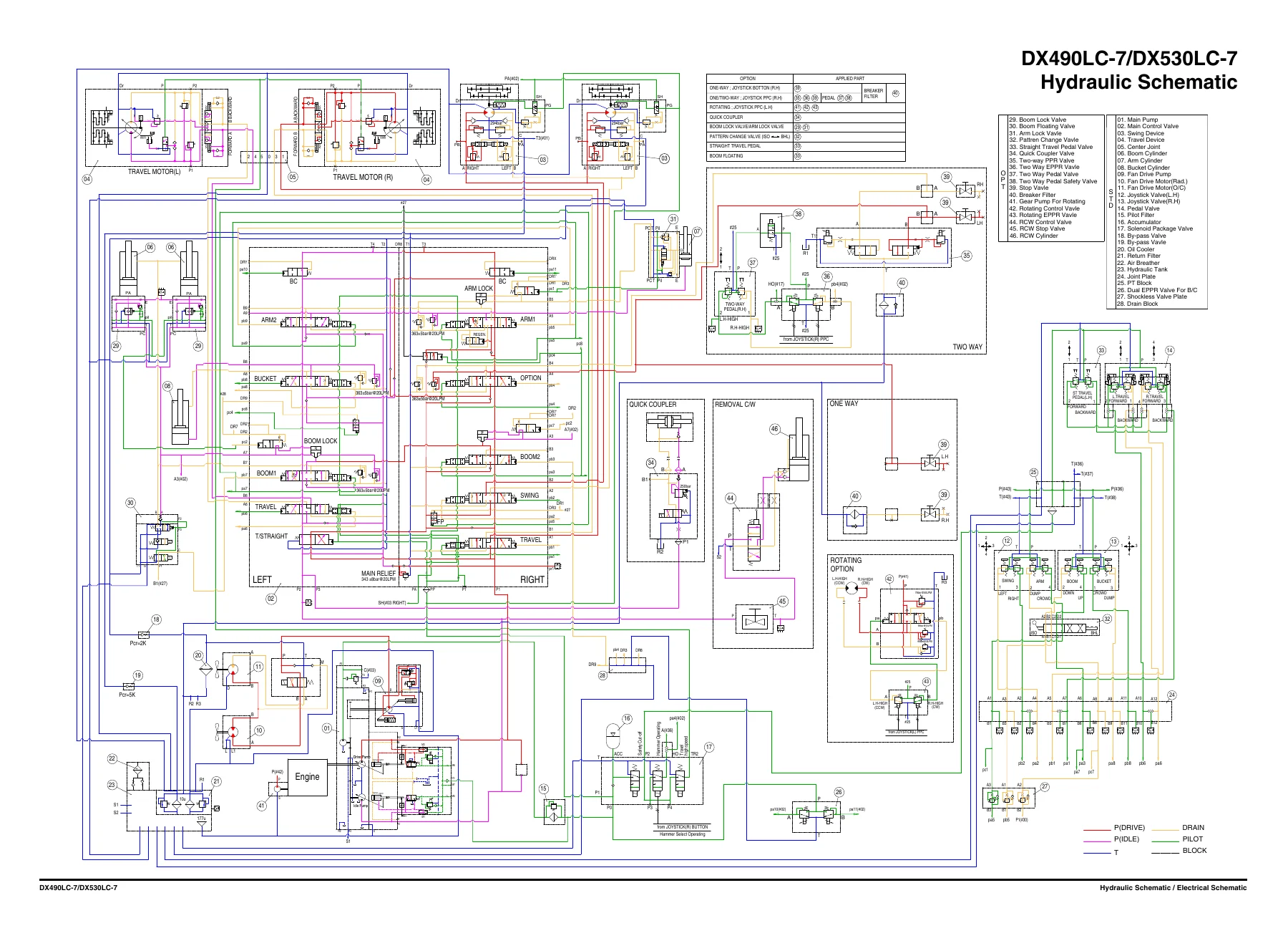
- Schematic – hydraulic schematic, electrical schematic
Beyond the table of contents, this Doosan shop manual goes deep on the systems that matter day-to-day on a 50-ton class excavator. The hydraulic section walks through the main oil circuit, pilot oil circuit, and return and drain circuit, then documents each function operation in turn – boom up and down, easy boom, arm dump and crowd, bucket dump and crowd, swing, travel, and travel straight. The component-level section covers the main pump with its regulator and angle sensor, the main control valve port map, swing device, fan pump and motor, joystick and travel control valves, solenoid valves, EPPR valves, center joint, and travel device, along with their port sizes, hydraulic circuits, and torque tables. The engine chapter covers valve clearance adjustment, mechanical system components, fuel system, lubricating system, cooling system, intake and exhaust, the VGT turbocharger, and the Stage V exhaust gas aftertreatment system with its SCR, DPF, DOC, and DEF components. The electrical chapter documents the fuse box and power supply flow, the starting and charging systems including the smart key option, the AVM system, the gauge panel service menu, the EPOS system, CAN communication, TMS, wiper system, and joystick multi-function features. The removal and installation chapters are organized system by system with step-by-step procedures, tool sizes, torque values, and component weights, so you know what to expect before you lift a pump, a swing device, or the cabin. The troubleshooting section is built around a wiring harness layout across the main, cabin, and battery harnesses, followed by EPOS and engine error code tables that map codes to faults, causes, and diagnostics procedures. The last section reproduces the hydraulic schematic and electrical schematic in full.
Engine, Aftertreatment, and Fluid Systems
The engine section of this DX490LC-7/DX530LC-7 shop manual is substantial because the machine uses a Stage V powerplant with a full exhaust gas aftertreatment package. You get valve clearance checking and adjustment with the flywheel engraving tables and cylinder adjustment order, general tightening torques for screw joints, engine suspension torque values, and then component chapters covering the camshaft, connecting rod, crankshaft, piston, power take-off, torsion damper, V-belt, balance shaft unit, and timing gear. The fuel system chapter covers tank design and positioning, fuel lines, fuel filter setup, feed pump flow rates, and the high pressure pump and injection system. Lubrication covers oil level checking, oil consumption assessment, and troubleshooting tips for high oil consumption including turbocharger oil leaks and worn piston rings. The cooling system section includes design and dimensioning guidance, expansion tank requirements, pressure drop and coolant flow, radiator and fan installation, cooling capacity checks, thermostat details, cab heater connection, and coolant filling. The intake and exhaust chapter covers exhaust system design, exhaust back pressure, insulation, V-clamps, exhaust bellows, intake air requirements, air cleaners, and crankcase ventilation. The aftertreatment chapter documents the Stage V system including the SCR catalytic converter, particulate filter, oxidation catalytic converter, reductant doser, NOx sensors, exhaust gas temperature sensors, differential pressure sensor, DEF (AdBlue) tank, reductant hoses, regeneration states and soot load thresholds, warning lamp strategy, and inducement levels.
Hydraulic and Electrical Systems
On the hydraulic side, the schematic is reproduced in full along with the main oil circuit, pilot oil circuit, and return and drain circuit descriptions. Each working function is documented with its own schematic and description, so you can trace oil flow from the main pump through the control valve to the cylinder, motor, or swing device for boom up, boom down, easy boom, arm dump, arm crowd, bucket dump, bucket crowd, swing, travel, and travel straight. The component descriptions include the main pump pressure-controlled dual pump with its EPPR valve, control piston, and angle sensor, the main control valve with its port names and sizes, swing device port layout, fan pump and motor port layouts, joystick and travel control valve theory of operation, solenoid valve ports, EPPR valve hydraulic circuits, center joint ports, and travel device port layout. The electrical system chapter documents fuse box layout and wiring connection logic, power supply flow from OFF/constant power through Key ACC and Key ON, starting system behavior including restarting protection and auto shut off, the smart key option with its OFF, ACC, ON, Start, and Emergency Starting conditions, the charging system and alternator, the AVM system, the gauge panel and service menu screens (monitoring, graph, failure information, operation hour information, machine configuration, attachment options, SW update, reset, version information, tolerance compensation, emergency code, permanent unlock), and the EPOS system with its controller inputs, outputs, and mode control tables for engine RPM and pump EPPR current. CAN communication between the control units is laid out with the CAN resistor values and connector references, so you can chase communication faults methodically.
Error Codes, Harness Layout, and Schematics
The troubleshooting portion of this manual is what makes it practical on the shop floor. The wiring harness layout section shows the main harness (both halves), the cabin harness (both halves), and the battery harness with each connector, device, and splice identified. The error code section lists EPOS error codes with failure details, machine actions, related information, causes, procedures, measuring locations, criteria, pop-ups, warning symbols, and block diagrams. Codes are given for items such as the gauge panel, E-ECU communication, pump proportional valves A and B, fan control proportional valve, pressure control proportional valves, flow control proportional valves, bypass cut-off valves, breaker solenoid valve, high-speed solenoid valve, reverse fan solenoid valve, option safety solenoid valve, free boom up and down solenoid valves, quick coupler solenoid valve, back buzzer relay, auto shut off relay, ACC relay, urea overcharging warning signal, external voice warning signal, wiper operating signal, pump pressure sensors, overload warning pressure sensor, boom up/down pressure sensors, bucket crowd/dump pressure sensors, arm in/out pressure sensors, travel pressure sensors, swing pressure sensor, option pedal pressure sensors, RCW pressure sensor, oil temperature sensor, fuel sensor, WIF sensor, angle sensors, thumb wheels, dial, machine controller +5 V outputs, and alternator potential. The engine error code list maps gauge panel fault codes to Scania SDP3 fault codes with descriptions and lamp status. The final section is the hydraulic schematic and electrical schematic, both reproduced in full.
Removal and Installation Procedures
The removal and installation chapters are organized into Engine, Hydraulic Systems, and Electric and Electronic. Before each section you get the preparatory work, general precautions, and completing work checklists. On the engine side, procedures are provided for the ECU, V-belt, alternator, starter motor, DEF quality sensor, aftertreatment sensors (SCR inlet temperature, DPF temperature, DOC inlet temperature, upstream NOx, downstream NOx, DPF pressure), and the complete engine assembly including undercover removal, coolant and hydraulic oil draining, hood removal, DPF and SCR assembly removal, support assembly, hydraulic hoses and wiring, main pump, air hoses and tubes, V-belt, alternator, air conditioner compressor, wiring connectors and cables, engine mount, and engine assembly lift. On the hydraulic side, procedures cover the main pump, drive coupling, undercovers, hydraulic oil tank, fuel tank, swing device, fan pump, oil cooler fan motor, joystick valve, travel control valve, center joint, travel device, main control valve, and cabin. Each procedure lists tool sizes, torque values, and component weights. On the electrical side, procedures cover the battery assembly, EPOS controller, TMS controller, AVM controller, microphone controller, smart key controller, wiper controller, DC-DC controller, cabin photo sensor, cabin switches, around view monitor, display monitor, hour meter, and wiper motor.
What This Doosan Shop Manual Enables You to Do
With this Doosan DX490LC-7 and DX530LC-7 Excavator Shop Manual in hand, you can carry out scheduled maintenance, diagnose hydraulic and electrical faults, read and interpret the error codes reported by the gauge panel, trace oil flow through the hydraulic circuits, follow the wiring harness from connector to connector, and remove and reinstall major assemblies with the correct tools and torque values. That matters because the DX490LC-7 and DX530LC-7 are large, complex machines with electronically controlled hydraulics, a Stage V engine and aftertreatment package, and multiple control units communicating over CAN. Guessing at torque values, hydraulic line routing, or sensor behavior on equipment like this leads to repeat failures, damaged components, and downtime. Having the correct procedures and reference values in front of you is what turns a difficult repair into a straightforward one.
This Doosan DX490LC-7/DX530LC-7 shop manual PDF is delivered instantly after payment. There is no shipping and no waiting for a disc or a printed book to arrive. The file can be opened on a laptop, tablet, or smartphone in the workshop, printed page by page for the job at hand, or kept on a shop computer as a permanent reference for the life of the machine. Whether you are a dealer technician, an independent mechanic, or an owner who prefers to handle service and repairs personally, this DX490LC-7 and DX530LC-7 shop manual gives you the documentation to do the job properly.
Reviews
There are no reviews yet.