

Komatsu D155AX-6 Bulldozer Shop Manual SEN00596-14 – Complete Service & Repair PDF for Serial 80001 and Up
Original price was: $79.95.$49.95Current price is: $49.95.
The complete Komatsu D155AX-6 shop manual covering serial numbers 80001 and up. Includes engine, power train, hydraulic, electrical, undercarriage, air conditioner and full disassembly/assembly procedures with specifications, testing, troubleshooting and diagrams.
Description
Komatsu D155AX-6 Shop Manual – SEN00596-14
This is the complete Komatsu shop manual for the D155AX-6 bulldozer, covering machines from serial number 80001 and up. It is the same technical documentation used by professional service technicians for maintenance, repair and overhaul of this crawler dozer. Every major system is covered in dedicated sections — from the SAA6D140E-5 engine through power train, hydraulics, undercarriage, electrical systems, air conditioning and complete disassembly and assembly procedures.
File Details
- Manual Type: Shop Manual (Service and Repair)
- Brand: Komatsu
- Model: D155AX-6
- Serial Numbers: 80001 and up
- Language: English
- File Format: PDF
- Document Number: SEN00596-14
- Publication Date: 2012
Chapters Covered
The manual is organized into the following top-level sections:
- 00 Index and foreword
- 01 Specification
- 10 Structure, function and maintenance standard
- 20 Standard value table
- 30 Testing and adjusting
- 40 Troubleshooting
- 50 Disassembly and assembly
- 80 Air conditioner
- 90 Diagrams and drawings
Engine and Cooling System
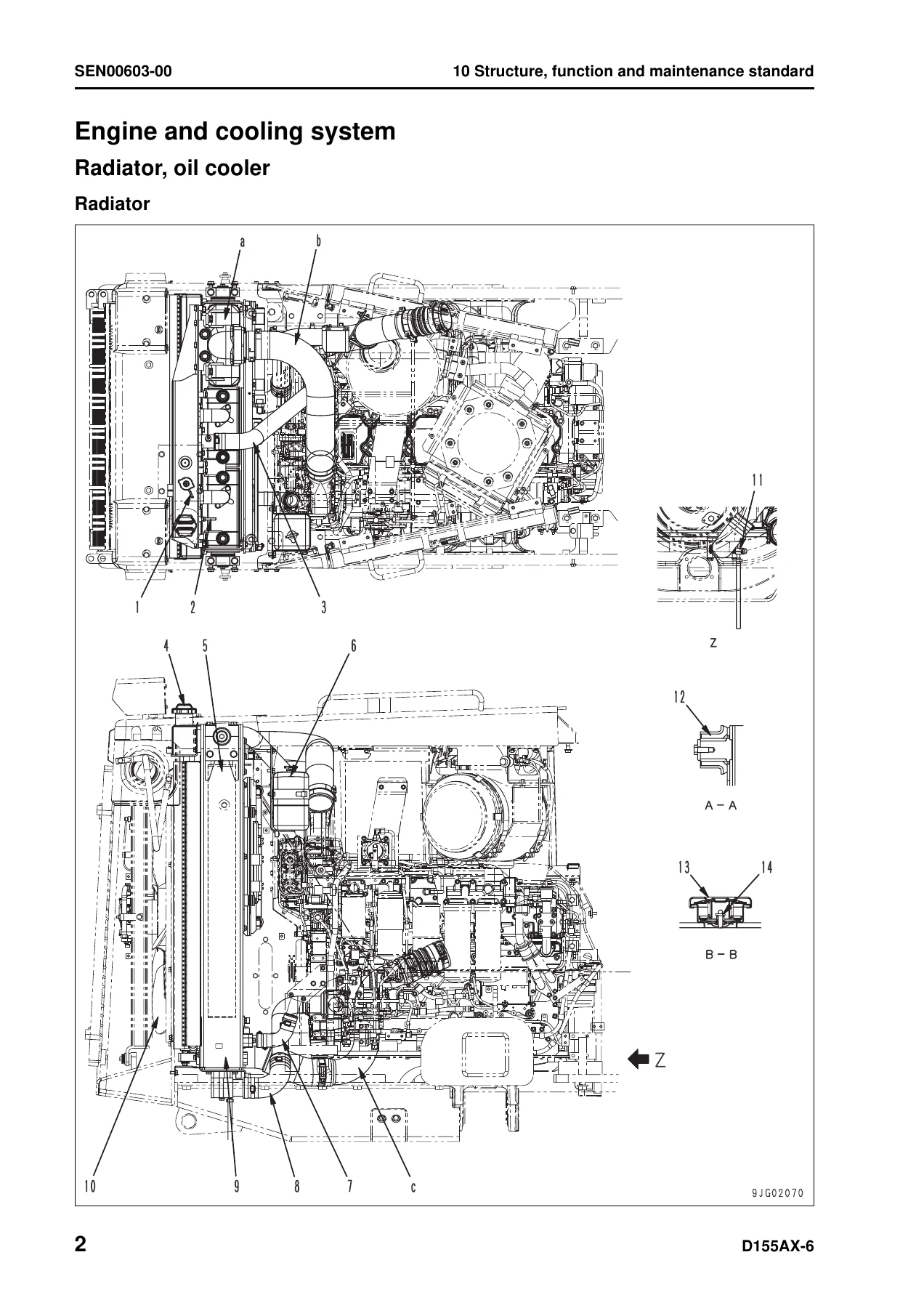
Covers the SAA6D140E-5 engine in full detail — a 4-cycle, water-cooled, in-line, vertical type, direct injection diesel with turbocharger, aftercooler and EGR cooler. Six cylinders with 140 mm bore and 165 mm stroke, 15.24 litre displacement. The cooling system section includes radiator, oil cooler, engine mount, cooling fan pump and cooling fan motor, with heat dissipation area, pressure valve specifications and maintenance standards. Engine performance data covers flywheel horsepower of 239 kW (320 HP) at 1,900 rpm, maximum torque of 1,715 Nm (175 kgm) at 1,300 rpm, and governed speeds.
Power Train (Parts 1, 2 and 3)
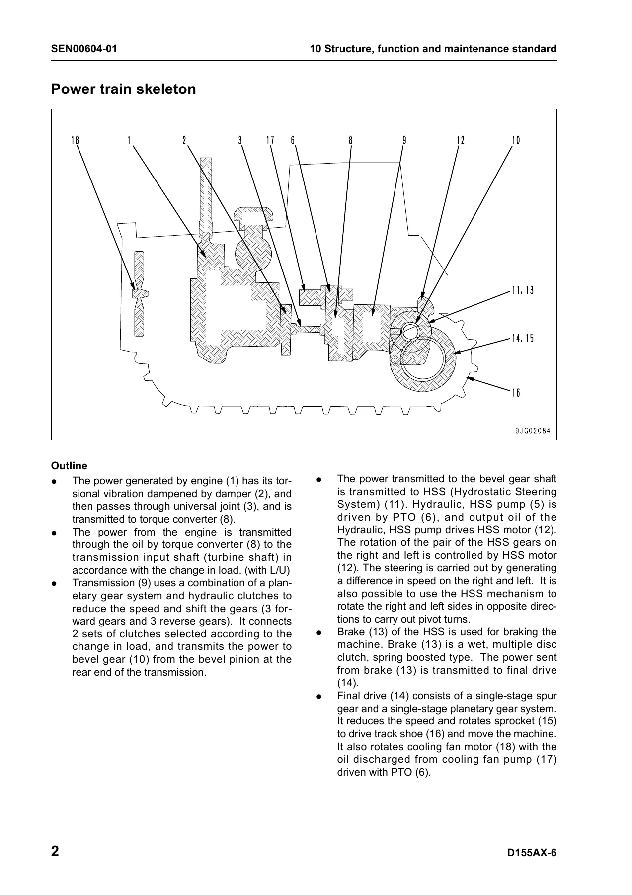
The power train section spans three major sub-sections. Part 1 covers the damper, universal joint, torque converter and PTO, torque converter control valve, lockup clutch ECMV, stator clutch ECMV, transmission control, transmission ECMV, main relief and torque converter relief valves, lubrication relief valve, scavenging pump and power train/steering lubrication pump. Part 2 covers the HSS (Hydrostatic Steering System) including the HSS motor, hydraulic HSS pump, hydraulic oil cooler bypass valve, steering and brake control, steering unit, brake control valve, parking brake solenoid valve, sudden stop prevention valve, final drive and sprocket. Part 3 covers removal and installation of the final drive assembly and its complete disassembly and assembly. Reduction ratios, clutch plate counts, backlashes, clearances and spring specifications are included throughout.
Undercarriage and Frame
Detailed coverage of the track frame, recoil spring, idler, track roller, carrier roller, track shoe, main frame and suspension. Includes maintenance standards for the K-shaped bogie suspension, track tension adjustment, recoil spring press-fitting force of 392 kN (40 ton), bushing press-fitting forces, and wear limits for track link pitch, bushing outside diameter, link height and shoe grouser height. Track shoe specifications cover both dry and sealed-and-lubricated types with 42 links per side and 228.6 mm pitch.
Hydraulic System
Covers the work equipment hydraulic piping, control piping, hydraulic tank and filter, accumulator, PCCS lever, work equipment lock valve, control valve (5-spool and 6-spool versions), work equipment cylinders, piston valve, quick drop valve and self pressure reducing valve. The control valve section includes the CLSS (Closed Center Load Sensing System) with steering priority valve, load check valve, pressure compensation valve and unload valve. Relief pressure settings include 27.5 ± 1.5 MPa (280 ± 15 kg/cm²) for work equipment and 25.0 ± 0.98 MPa (255 ± 10 kg/cm²) for work equipment LS relief.
Work Equipment
Covers the cylinder stay, blade (Sigma-tilt and semi U-tilt), cutting edge and end bit, and ripper (variable multi-shank and variable giant). Blade capacities, cutting angles, lifting heights and digging depths are specified for each blade type. The ripper section covers shank positions, digging depth, lifting height and point angle ranges.
Cab and Its Attachments
Cab mount and ROPS pin specifications, ROPS cab construction, and air conditioner piping layout including condenser, receiver tank, refrigerant piping, compressor and air outlets. The air conditioner section explains the refrigerant circuit, component functions and service procedures.
Electrical System
Engine control, engine control system, deceleration potentiometer, monitor system, sensors, Palm Command Control System (PCCS) and KOMTRAX system. The monitor system section covers the machine monitor functions, gauge displays, warning systems and service mode. Sensor specifications include engine oil pressure sensor, engine coolant temperature sensor, torque converter oil temperature sensor, hydraulic oil temperature sensor, coolant level sensor, fuel level sensor, engine speed sensor, bevel gear speed sensor and pitch angle sensor.
Standard Value Table
The standard service value table provides engine and machine specifications for new machines and service limit values. Engine data includes high idle speed of 2,100 rpm, low idle of 740 rpm, rated speed of 1,900 rpm, intake air pressure (boost pressure) minimum 117 kPa (880 mmHg), exhaust temperature of 660°C, valve clearance (intake 0.35 mm, exhaust 0.57 mm), compression pressure minimum 4.1 MPa (42 kg/cm²), blow-by pressure maximum 2.94 kPa (300 mmH₂O), and engine oil pressure minimum 0.34 MPa (3.5 kg/cm²) at high idle. Machine data includes travel speeds, torque converter stall speed of 1,610 ± 50 rpm, fan motor speed of 1,250 ± 50 rpm, and control lever stroke specifications.
Testing and Adjusting
Four parts covering tools for testing and adjusting, measuring engine speed, intake air pressure, exhaust temperature and exhaust gas colour, adjusting valve clearance, measuring compression pressure, blow-by pressure, engine oil pressure, testing EGR valve and bypass valve drive oil pressure, handling fuel system parts, releasing residual pressure, measuring fuel pressure, fuel return rate and leakage, bleeding air from fuel circuit, testing and adjusting alternator belt tension and air conditioner compressor belt tension, measuring fan speed and fan circuit oil pressure, adjusting fuel control dial and decelerator pedal, measuring power train oil pressure, adjusting transmission output shaft speed sensor, simple brake performance test, adjusting brake pedal and parking brake lever, emergency escape methods, adjusting idler clearance, track shoe tension, measuring and adjusting work equipment and HSS oil pressure, measuring control circuit basic pressure, work equipment lock solenoid valve output pressure, emergency operation methods, ripper pin puller solenoid valve output pressure, testing hydraulic drift causes, measuring internal leakage, releasing residual pressure, bleeding air, adjusting work equipment lock lever, blade and operator’s cab.
Troubleshooting
Comprehensive troubleshooting covering failure code tables, fuse locations, information in troubleshooting tables, general troubleshooting information, sequence of events, classification and procedures, connection tables for connector pin numbers and T-branch box/adapter tables. Troubleshooting by failure and error codes is split into eight parts covering transmission clutch, forward/reverse clutch, speed clutches, lockup, brakes, ECM hold relay, air cleaner clogging, battery charge, engine oil pressure, engine water overheat, engine water level, torque converter oil overheat, hydraulic oil overheat, and hundreds of specific failure codes with causes, standard values and remedies. Electrical system troubleshooting (E-mode) covers power supply, engine starting, preheating, gauges, monitor functions, air conditioner, ripper pin puller, backup alarm, lamps, wipers and KOMTRAX. Hydraulic and mechanical system troubleshooting (H-mode) covers power, travel, steering, brakes, oil temperature and work equipment issues. Engine troubleshooting (S-mode) covers starting performance, engine stop, smoothness, output, exhaust colour, oil consumption, oil contamination, fuel consumption, coolant contamination, oil pressure, oil level rise, overheating, noise and vibration.
Disassembly and Assembly
General information on disassembly and assembly, coating materials list, special tool list and sketches. Engine and cooling system procedures cover fuel supply pump, fuel injector, cylinder head, radiator, aftercooler, engine, engine hood, engine front seal, engine rear seal, fuel tank, fan drive and fan motor. Power train procedures cover damper, power train unit, PTO, torque converter, transmission, HSS case and HSS motor. Final drive procedures cover removal, installation and complete disassembly/assembly. Undercarriage procedures cover track frame, idler, recoil spring, track roller, bogie assemblies, carrier roller, pivot shaft, track shoe spreading, track shoe general disassembly/assembly, one-link field disassembly/assembly, master link, equalizer bar and segment teeth. Hydraulic system procedures cover hydraulic tank, hydraulic pump and hydraulic cylinder. Work equipment procedures cover blade and multi-shank ripper. Cab and attachments procedures cover operator’s cab, cab glass, floor frame and air conditioner unit. Electrical system procedures cover engine controller, power train controller and work equipment controller.
Air Conditioner
Structure and function of the air conditioner system including component layout, refrigerating cycle configuration, air conditioner unit, functions of major components, control plate, compressor, condenser and receiver drier. Testing, adjusting and troubleshooting covers refrigerant handling, troubleshooting procedure, block diagram, circuit diagram and connector pin arrangement, detail of air conditioner unit, part and connector locations, testing air leakage, self-diagnosis function, temperature control, vent changeover, recirc/fresh changeover, inner sensor, evaporator temperature sensor, sunlight sensor, pressure switch, relays and diodes, troubleshooting charts, electrical system troubleshooting (E-mode) and gauge pressure troubleshooting. Service tool connection, compressor oil handling and refrigerant caution are also covered.
Diagrams and Drawings
Power train hydraulic circuit diagram, hydraulic circuit diagrams for serial numbers 80001–80806 and 80807 and up, electrical circuit diagrams (12 sheets), electrical circuit diagram for inside cab, and connectors table and arrangement drawing. The connectors table lists every connector with its number, type, pin count, location and address — covering starting switch terminals, air conditioner compressor, controllers, sensors, solenoids, relays, fuses, circuit breakers, lamps, wipers and more.
Everything You Need to Service the D155AX-6
This Komatsu D155AX-6 shop manual gives you the complete factory service information for the D155AX-6 bulldozer. Whether you are performing routine maintenance, diagnosing a fault code, adjusting a clutch, rebuilding a final drive or overhauling the engine, this manual contains the procedures, specifications, torque values, wear limits and diagnostic flowcharts you need to do the job correctly. It is not a generic guide — it is the exact documentation for serial numbers 80001 and up.
The manual covers every major system in depth. The engine section alone provides compression pressures, valve clearances, oil pressures, blow-by limits and fuel system test values. The power train section includes clutch pressures, relief valve settings, spring free lengths and clearance limits. The undercarriage section gives wear limits for every track component. The hydraulic section provides relief pressures, LS differential pressures and control valve specifications. The electrical section includes the complete monitor system, sensor specifications and every failure code with troubleshooting steps.
When you are working on a heavy machine like the D155AX-6, using the correct procedures and specifications is not optional — it is essential. An incorrect clutch pressure can destroy a transmission. A wrong valve clearance can damage an engine. A misadjusted track tension can cause premature wear. This manual removes the guesswork. It tells you what to measure, what the reading should be, and what to do if it is outside the standard. The troubleshooting sections are particularly valuable — they walk you through failure code by failure code, symptom by symptom, so you can find the root cause instead of replacing parts blindly.
Delivery is instant. Once your order is complete, you receive the PDF immediately — no shipping, no waiting, no physical media. The file opens on any device: laptop, desktop, tablet or smartphone. You can search, zoom, print the pages you need for the workshop, or keep the entire manual on a USB drive in your service truck. The PDF format means you can have the whole manual with you wherever the machine is.
This is a large, comprehensive manual — over 1,500 pages of technical information. It covers the D155AX-6 thoroughly and is organized so you can find what you need quickly. If you own, operate, maintain or repair a D155AX-6 bulldozer, this shop manual is an essential tool. Get instant access and keep your machine running at its best.
IMAGES PREVIEW
Reviews
There are no reviews yet.