
Komatsu D475A-5 Serial 20001 and Up Shop Manual SEBM033701 PDF
Original price was: $44.95.$26.95Current price is: $26.95.
971-page Komatsu D475A-5 shop manual for machines with serial number 20001 and up, covering specifications, structure and function, maintenance standards, testing and adjusting, troubleshooting, and hydraulic and electrical circuit diagrams. Document SEBM033701.
Description
Komatsu D475A-5 Serial 20001 and Up Shop Manual SEBM033701 PDF
The Komatsu D475A-5 Serial 20001 and Up Shop Manual SEBM033701 PDF is a detailed technical reference for D475A-5 machines with serial number 20001 and up. This volume combines machine specifications, structure and function explanations, maintenance standards, testing and adjusting procedures, troubleshooting information, and hydraulic and electrical circuit diagrams. It covers the chassis and work-equipment systems in substantial depth, including the power train, steering and brakes, undercarriage, work equipment hydraulics, controls, cab systems, monitoring, and electronic control systems.
File Details
- Manual type: Shop Manual
- Brand / model: Komatsu D475A-5
- Serial coverage: 20001 and up
- Engine fitted: SDA12V140E-1
- Language: English
- Page count: 971 pages
- File format: PDF
- Document number: SEBM033701
- Publication marking: © 2003; Printed in Japan 11-03 (01)
The manual identifies the D475A-5 as mounting the SDA12V140E-1 engine and directs the reader to the separate 12V140-1 Series Engine Shop Manual for detailed engine information. Engine standard values, measurements, adjustments, and engine-body troubleshooting are nevertheless included in this D475A-5 volume where they relate to machine testing and diagnosis.
Machine Coverage and Technical Reference
This Komatsu D475A-5 shop manual covers the machine in Semi-U tiltdozer, Full-U tiltdozer, and Superdozer configurations shown in the specification section, together with ripper-related equipment described in the manual. General data includes specification drawings, machine dimensions, weights, travel performance, engine data, power-train construction, undercarriage details, work-equipment hydraulic data, blade and ripper specifications, component weight tables, and fuel, coolant, and lubricant information.
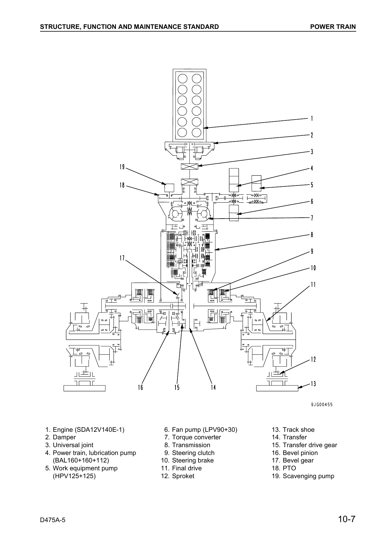
The specification pages identify the SDA12V140E-1 as a water-cooled V-type direct-injection engine with turbocharger and aftercooler. The manual also details the torque converter with lock-up clutch, planetary transmission with three forward and three reverse speeds, wet multiple-disc steering clutch and brake arrangements, final drives, suspension, rollers, track shoes, hydraulic pumps, control valves, cylinders, and related control systems. These reference sections are paired with maintenance-standard tables containing inspection dimensions, clearances, backlash values, wear criteria, repair limits, spring data, pressures, torque information, and other decision points used during service evaluation.
Chapters Covered
- 01 General
- Specification drawings and dimensions
- Specifications for Semi-U tiltdozer, Full-U tiltdozer, and Superdozer configurations
- Weight tables for major machine components and work equipment
- Fuel, coolant, lubricants, specified capacities, and refill capacities
- 10 Structure, Function and Maintenance Standard
- Radiator, oil cooler, engine mount, damper, and universal joint
- Power train layout, hydraulic arrangement, power train unit, torque converter and PTO
- Torque converter valve and lock-up control system
- Scavenging pump, transmission control, transmission, transmission ECMV, and clutch ECMV
- Priority valve, lubricating oil relief valve, and power train lubrication pump
- Steering and brake control, steering unit, steering ECMV, clutch ECMV, brake ECMV, parking brake, and sudden-stop prevention valve
- Final drive, sprocket, track frame, recoil spring, idler, track roller, carrier roller, bogie, and track shoe
- Main frame and suspension
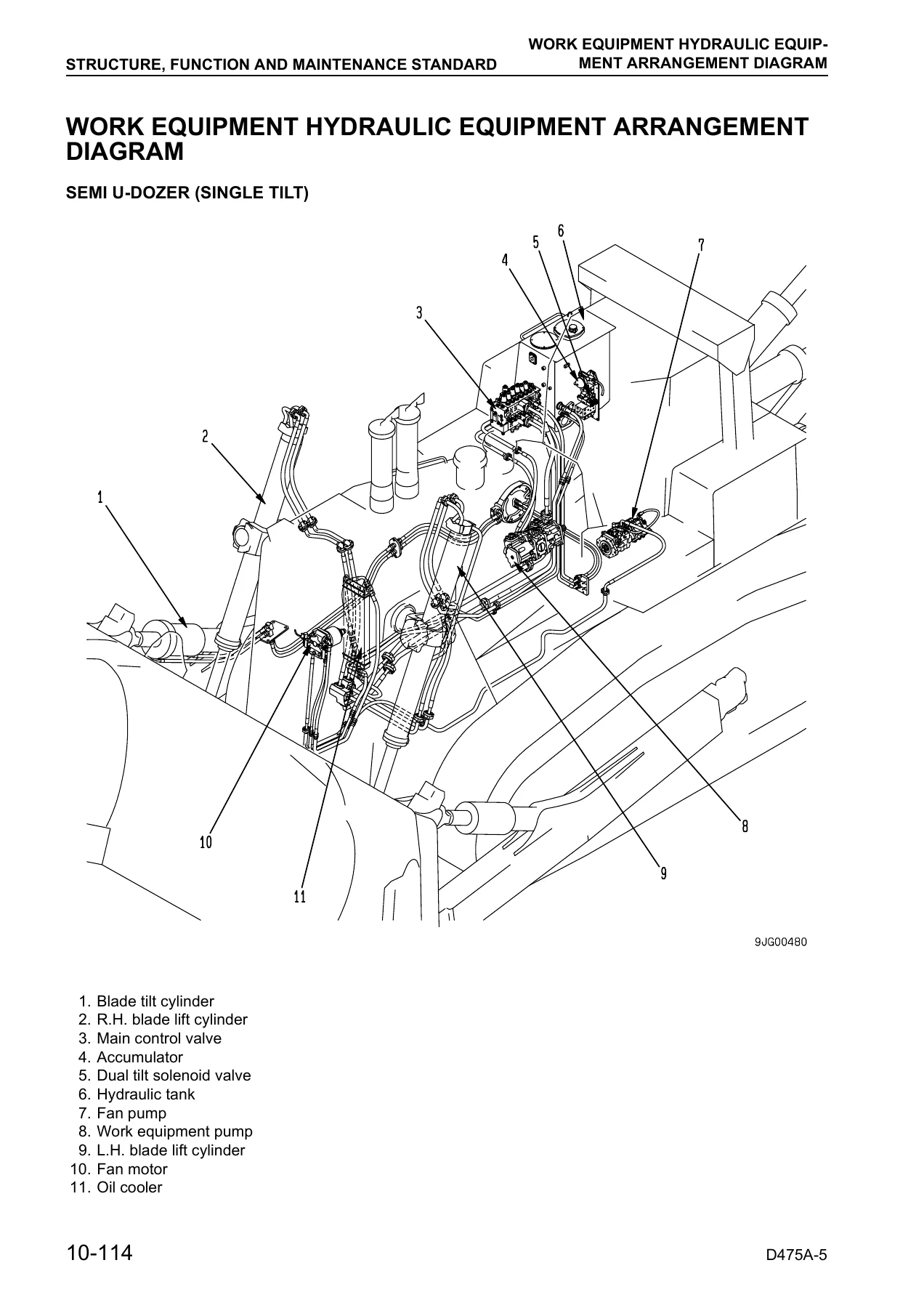
- Work-equipment hydraulic arrangement for dozer and ripper configurations
- PPC control piping and work-equipment control
- Work-equipment pump, cooling fan pump, cooling fan motor, PPC valve, and electric steering lever
- Control valve, main relief valve, CLSS, unload valve, LS pressure circuits, LS bypass plug, and pressure compensation valve
- Blade lift valve, merge-divider valve, self-reducing pressure valve, and pilot solenoid valve
- Hydraulic tank, accumulator, work-equipment cylinder, piston valve, and quick-drop valve
- Blade control knob, pitch and dual solenoid valve, and pin-puller hydraulic circuit
- Cylinder stay, blade, and ripper equipment
- Cab mount, cab, and air conditioner
- Engine control, deceleration potentiometer, electronic engine throttle controller, and electronic-governor fuel injection pump
- Monitor system, monitor panel, sensors, and mode selection system
- Electrical equipment and steering electronic control system
- VHMS controller, sensors, and communication controller / antenna
- 20 Testing and Adjusting
- Standard value tables for engine and chassis
- Testing, adjusting, and troubleshooting devices table
- Engine speed, boost pressure, exhaust temperature, exhaust gas color, valve clearance, compression, blow-by, engine oil pressure, and fuel injection timing
- Alternator and air-conditioner compressor belt checks and engine speed sensor adjustment
- Fuel control dial and decelerator pedal adjustment
- Power train oil pressure measurement and transmission speed sensor adjustment
- Brake performance, brake pedal, parking brake lever, and PCCS lever adjustments
- Emergency escape method when the power train has trouble
- Idler clearance, sprocket wear, and track shoe tension checks
- Work-equipment oil pressure and control-circuit basic pressure testing
- PPC valve and solenoid-valve output pressure measurement
- Hydraulic drift checks, work-equipment cylinder internal leakage, residual-pressure release, and air bleeding
- Blade and ripper control adjustments
- Fan motor speed and fan-circuit oil pressure measurement
- Blade tilt control-angle measurement for dual tiltdozer and Superdozer specifications
- Operator cab testing and blade adjustment
- Monitor-panel special functions, replacement-controller adjustment, optional devices, VHMS initialization, Quick PM, and PM Clinic service
- Troubleshooting preparation, connector arrangements, connector pin tables, and T-branch information
- Electrical-system troubleshooting, hydraulic/mechanical troubleshooting, and engine-body troubleshooting
- 30 Disassembly and Assembly
- This contents entry is marked “To be issued next time” in this edition and is not included as a completed chapter in the PDF.
- 90 Others
- Power train hydraulic circuit diagram
- Work-equipment hydraulic circuit diagrams, 3 sheets
- Electrical circuit diagrams, 8 sheets
- Electrical circuit diagram of inside cab
Taken together, these chapters give a technician both a systems-level explanation of how the D475A-5 works and the measurement data needed to evaluate its condition. The structure-and-function material is particularly useful when tracing power flow, hydraulic operation, steering and braking behavior, electronic modulation, work-equipment control, and undercarriage wear. The testing section then links those systems to practical checks, pressures, speeds, adjustments, service limits, connector information, and troubleshooting paths.
Testing, Adjustment and Troubleshooting Depth
The Komatsu D475A-5 Serial 20001 and Up Shop Manual SEBM033701 PDF contains extensive procedures for checking machine condition before replacing parts. Engine-related checks include speed, intake-air pressure, exhaust temperature and color, compression, blow-by, oil pressure, injection timing, and valve clearance. Chassis testing extends to power-train pressures, transmission and steering controls, brake operation, track tension, work-equipment pressure, PPC and solenoid pressure, cylinder leakage, fan-system pressure, control angles, and cab-related checks.
Troubleshooting is organized around preparatory checks, connector and circuit information, service and failure codes, and dedicated diagnostic paths for electrical, hydraulic/mechanical, and engine-body problems. This makes the manual useful for identifying likely causes from symptoms and measurements instead of relying only on component replacement. The document also includes standard values and service-limit criteria intended to help judge wear and machine condition during repair work.
Hydraulic, Electrical and Control-System Diagrams
Hydraulic and electrical information is distributed throughout the manual rather than confined to a single chapter. Structure-and-function pages show component arrangements and operating circuits for the power train, torque converter, transmission, steering, brakes, work equipment, blade and ripper controls, pumps, valves, and electronic modulation systems. The final Others section adds a complete power-train hydraulic circuit diagram, three work-equipment hydraulic circuit sheets, eight electrical circuit sheets, and an inside-cab electrical circuit diagram.
For fault tracing, the manual also provides electrical connector arrangement drawings, connector pin-number tables, troubleshooting preparation, monitoring functions, sensors, controller information, VHMS-related procedures, and system-specific diagnostic material. This combination helps connect a reported symptom to the appropriate circuit, test point, component, adjustment, or standard value.
Get the D475A-5 Service Information Ready for the Job
The Komatsu D475A-5 Serial 20001 and Up Shop Manual SEBM033701 PDF supports a wide range of inspection, testing, adjustment, troubleshooting, maintenance-standard, hydraulic, electrical, power-train, steering, brake, undercarriage, blade, ripper, and control-system work on covered D475A-5 machines. Correct pressures, dimensions, clearances, service limits, circuit layouts, and test procedures matter when diagnosing faults and deciding whether components are within usable limits.
IMAGES PREVIEW
This edition does not include the Disassembly and Assembly chapter shown in the contents; that entry is specifically marked as being issued next time. Detailed engine service is also referred to the separate 12V140-1 Series Engine Shop Manual. For the extensive chassis, systems, testing, troubleshooting, and circuit information contained here, the manual is supplied as an instant PDF download after payment, with no shipping required. Open it on a compatible phone, tablet, laptop, or desktop, and print the pages you need for workshop reference.



Reviews
There are no reviews yet.