
Komatsu PC138US-8 PC138USLC-8 Shop Manual SEN01968-02 – Complete PDF Workshop Service & Repair Manual
Original price was: $63.95.$39.95Current price is: $39.95.
The complete Komatsu PC138US-8 and PC138USLC-8 Shop Manual (SEN01968-02), covering specifications, engine and cooling, power train, undercarriage, hydraulics, work equipment, cab, electrical systems, testing and adjusting, troubleshooting, disassembly and assembly, plus full hydraulic and electrical diagrams. Instant PDF download — no shipping, print any page.
Description
Komatsu PC138US-8 & PC138USLC-8 Shop Manual — SEN01968-02
This is the full Komatsu PC138US-8 and PC138USLC-8 hydraulic excavator Shop Manual, document number SEN01968-02. It is the multi-section workshop reference that covers the machine from the engine and cooling system right through to the electrical diagrams — the same body of technical information a workshop uses to service, test, adjust, diagnose and rebuild the PC138US-8 and the long-undercarriage PC138USLC-8 (serial numbers 20001 and up).
Unlike a single-topic booklet, this manual is compiled from the full set of Komatsu shop manual forms, so the same PDF carries specification and technical data, structure and function, standard value tables, testing and adjusting procedures, failure-code troubleshooting, disassembly and assembly procedures, and the hydraulic circuit and electrical circuit diagrams.
File Details
- Manual type: Shop Manual (workshop service, repair, testing and troubleshooting)
- Brand: Komatsu
- Models covered: PC138US-8, PC138USLC-8
- Serial numbers: 20001 and up
- Language: English
- File format: PDF
- Document number: SEN01968-02 (with the individual section form numbers SEN01969-02 through SEN02716-00)
- Date: 2007
- Page count: Approximately 946 pages
Chapters Covered
- 00 Index and foreword
- 01 Specification
- 10 Structure, function and maintenance standard
- 20 Standard value table
- 30 Testing and adjusting
- 40 Troubleshooting
- 50 Disassembly and assembly
- 90 Diagrams and drawings
00 — Index and Foreword
The opening section holds the shop manual contents and composition, a safety notice with general precautions, preparation and working precautions, sling work and sign-making precautions, guidance on selecting wire ropes, precautions for disconnecting and connecting air-conditioner hoses and tubes, and the general information that frames the rest of the manual. It also contains the explanation of maintenance-standard terms, handling of electric equipment and hydraulic components, engine connector handling, how to read electric wire codes, the standard tightening torque tables and conversion tables.
01 — Specification
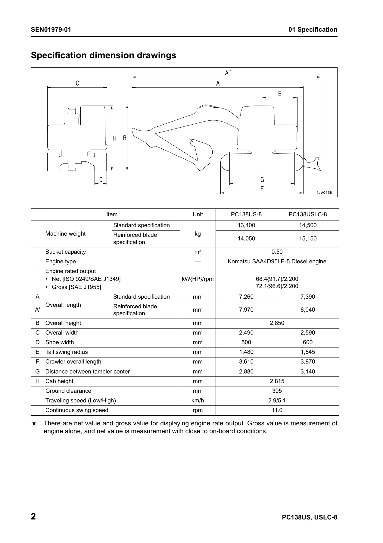
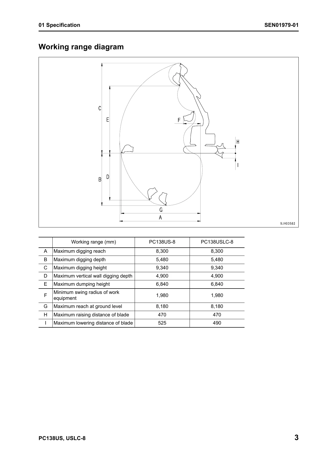
Specification dimension drawings, the working range diagram, the specification tables for the standard and reinforced-blade machine variants, the list of weights and the table of fuel, coolant and lubricants are all here. Machine weight, bucket capacity, engine output, overall length, overall height, overall width, shoe width, tail swing radius, crawler overall length, ground clearance, travel speed, swing speed, working range and ground pressure are all specified in these tables for the PC138US-8 and PC138USLC-8.
10 — Structure, Function and Maintenance Standard
This is one of the largest sections. Engine and cooling system, power train, undercarriage and frame, the hydraulic system in three parts, work equipment, cab and its attachments, and the electrical system are each covered. You get engine mount and PTO, cooling system layout, the swing circle with bearing clearance and lubrication details, swing machinery with all the planetary gear backlashes, the track frame, idler cushion, idler, track roller, carrier roller, sprocket and track shoe wear limits. The hydraulic system parts cover the hydraulic equipment layout, valve control, hydraulic tank and filter, the hydraulic pump (type HPD56+56) with its PC valve, LS valve and EPC valve, the control valve (six- to nine-spool variants), the CLSS pressure compensation system, PPC valves, travel motor, swing motor, center swivel joint, solenoid valves, PPC accumulator, holding valve and multi-control valve. Work equipment gives the pin and bushing clearances, component dimensions and hydraulic cylinder criteria, and cab and its attachments covers the air-conditioner piping and components. The electrical section covers the electronic control system, monitor system, KOMTRAX system and sensors.
20 — Standard Value Table
Standard value tables for engine related parts and chassis related parts. Engine speed, exhaust gas colour, valve clearance, compression pressure, blow-by pressure, engine oil pressure, oil temperature, fan belt and air-conditioner belt tension are listed on the engine side, and control lever travels and plays, operating efforts, hydraulic pressures (unload, boom relief, arm relief, bucket relief, swing relief, blade relief, travel relief), control circuit source pressure, servo piston input pressure, LS differential pressure, swing overrun and swing times, travel speeds, travel deviation, hydraulic drift values, work equipment speeds, time lags and internal leakage limits are all specified with service limit values on the chassis side.
30 — Testing and Adjusting
This three-part section tells you which testing, adjusting and troubleshooting tools are used, then walks through testing engine speed, exhaust temperature, exhaust gas colour, valve clearance adjustment, compression pressure, blow-by pressure, engine oil pressure, fuel system handling and residual-pressure release, fuel pressure, fuel return rate and leakage, air bleeding from the fuel circuit, fuel circuit leakage checks, alternator belt tension, swing circle bearing clearance, air-conditioner compressor belt tension, and track shoe tension. It then covers oil pressure in the work equipment, swing and travel circuits, control circuit basic pressure, pump PC control circuit pressure, pump LS control circuit pressure, solenoid valve output pressure, PPC valve output pressure, PPC valve play adjustment, hydraulic drift diagnosis, travel deviation, residual pressure release, oil leakage testing, air bleeding from each part, cab tipping stopper and mirror adjustment. Part 2 is the special functions of the machine monitor, and Part 3 covers the engine controller voltage circuit, electrical-system troubleshooting preparation, diode testing and the Pm Clinic service check sheet.
40 — Troubleshooting
This is the diagnostic heart of the manual. It begins with the failure code table and fuse locations, general troubleshooting information, the sequence of events, checks before troubleshooting, classification and procedures, and the phenomena that look like troubles and their troubleshooting numbers. The failure-code troubleshooting then runs in four parts covering engine controller lock cautions, charge voltage, engine oil pressure and level, coolant overheat, hydraulic oil overheat, ECM critical internal failure, Ne and Bkup speed sensor errors, charge air pressure and temperature sensors, throttle sensor, coolant temperature sensor, sensor supply voltages, engine overspeed, IMV/PCV1, injectors #1 to #4, injector drive circuit, engine oil pressure switch, battery voltage, rail pressure sensors, rail pressure high and low, engine Ne and Bkup speed sensors, KOMNET datalink timeout, throttle sensor supply voltage, rail pressure very low, IMV solenoid, battery relay drive, personal code relay, GPS antenna, pump solenoid power, 5V sensor power supplies, CAN disconnection, camera power supply, GPS module, hydraulic oil sensor, pump pressure sensor, travel and blade PPC pressure sensors, overload sensor, travel alarm, travel speed solenoid, swing brake solenoid, travel junction solenoid, merge-divider solenoid, PC-EPC solenoid, service current EPC, wiper and washer drive circuits. The E-mode electrical troubleshooting covers the machine monitor, starting, preheating, auto warm-up, work equipment, swing and travel lock, precaution and emergency-stop indications, gauges, travel speed, alarm buzzer, windshield wiper and washer, swing holding brake, travel alarm, air conditioner, service meter, service mode, lever control signal monitoring and KOMTRAX. The H-mode covers hydraulic and mechanical system troubleshooting for work equipment, swing and travel, and the S-mode covers engine troubleshooting from starting performance through to vibration.
50 — Disassembly and Assembly
General information on disassembly and assembly, the list of adhesives, the special tool list and special tool sketches, then the removal and installation procedures for the fuel supply pump, fuel injector, front and rear oil seals, cylinder head, radiator, aftercooler, work equipment oil cooler, engine and work equipment pump, fuel tank, travel motor and final drive, swing motor and swing machinery, swing circle, track roller, idler, recoil spring, track shoe, sprocket, revolving frame, counterweight, center swivel joint, hydraulic tank, hydraulic pump, control valve, work equipment and travel PPC valves, hydraulic cylinder, work equipment assembly, operator cab, cab glass, front window, floor frame, air compressor, air conditioner condenser and unit, machine monitor, pump controller, engine controller and KOMATRAX communications module.
90 — Diagrams and Drawings
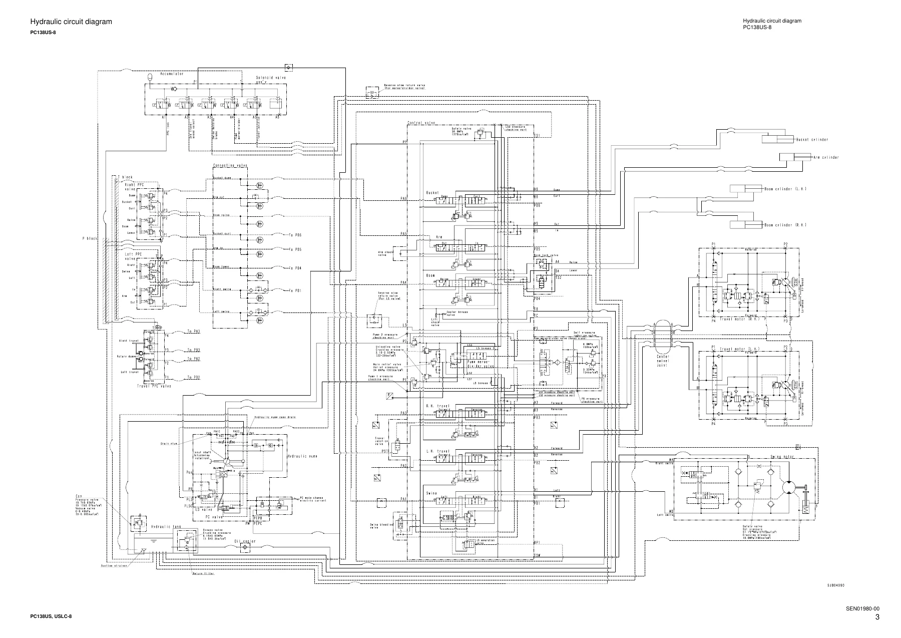
Hydraulic circuit diagrams for the PC138US-8, the blade specification and machine ready for attachment, the PC138USLC-8 (KA specification), and the PC138US-8 (KUK specification). The electrical diagrams and drawings include the electrical circuit diagram and the connectors table and arrangement drawing.
Why This Komatsu PC138US-8 / PC138USLC-8 Shop Manual Matters
The PC138US-8 and PC138USLC-8 are compact-radius hydraulic excavators that use a full load-sensing hydraulic system with electronic pump control, and the machine-specific torque values, clearances, pressures and failure codes in this manual are what make accurate work possible. Guessing at a swing machinery backlash, a main relief pressure, an LS differential pressure or a control valve spring installed load wastes parts and time. Having the SEN01968-02 shop manual on hand means you can check the standard value, identify the failure code, follow the correct disassembly order, apply the correct tightening torque and sealant, and put the machine back together correctly. It supports engine work, hydraulic pump and valve work, travel and swing component overhaul, undercarriage service, electrical diagnostics and air-conditioner service on the PC138US-8 and PC138USLC-8.
IMAGES PREVIEW
Instant PDF Delivery
This Komatsu PC138US-8 and PC138USLC-8 shop manual is supplied as a PDF download. There is no shipping, no waiting and no physical book to store. Once the download completes you can open it on a workshop laptop, a tablet or a phone, search the text, and print only the pages you need for the job — a full hydraulic circuit diagram, a disassembly procedure, a torque table or a troubleshooting flowchart. Keep it on the machine laptop for quick reference during diagnostics, or print the section you are working on and take it to the machine. For anyone maintaining, repairing or diagnosing a PC138US-8 or PC138USLC-8, this is the reference that keeps the work accurate.



Reviews
There are no reviews yet.