
Komatsu D475A-8R Bulldozer Field Assembly Manual GEN00241-00
Original price was: $39.95.$23.95Current price is: $23.95.
Complete field assembly manual for the Komatsu D475A-8R bulldozer, document GEN00241-00. Covers every stage of reassembling the delivered kits into a complete machine – track frames, final drives, cab, blade, ripper, hydraulic bleeding, and final inspection. 325 pages, English.
Description
Komatsu D475A-8R Bulldozer Field Assembly Manual GEN00241-00
This is the complete field assembly manual for the Komatsu D475A-8R bulldozer, document number GEN00241-00. The D475A-8R is shipped from the factory in multiple separate units to meet transportation regulations, and this manual is what tells the assembly crew how to put the machine back together correctly at the assembly site. Every stage is covered – from unloading the kits and positioning the chassis stands, through installing the track frames, final drives, cab, blade, and ripper, right up to the final inspection report and Quick PM procedure.
Written for the work supervisor, work leader, and assembly team, the manual opens with safety and work-procedure precautions before moving into the detailed step-by-step assembly sequence. Each procedure includes the tools and equipment required, part lists with part numbers, tightening torques, coating materials, and photographs or line drawings showing the correct method. The document is the authoritative reference for any Komatsu D475A-8R field assembly job.
File Details
- Manual Type: Field Assembly Manual
- Brand: Komatsu
- Model: D475A-8R Bulldozer
- Document Number: GEN00241-00
- Engine Model: SAA12V140E-7
- Language: English
- Page Count: 325
- File Format: PDF
- Publication: 05-22 (May 2022)
- Blade Options Covered: Semi-U, Full-U, Superdozer
- Ripper Options Covered: Variable giant ripper, multi-shank ripper, counterweight
- Shoe Widths Covered: 710 mm, 810 mm, 910 mm
Chapters Covered
The Komatsu D475A-8R field assembly manual is organized into the following major sections:
- Disposal of Removed Parts
- Assembly Procedure, Necessary Equipments, and Schedule
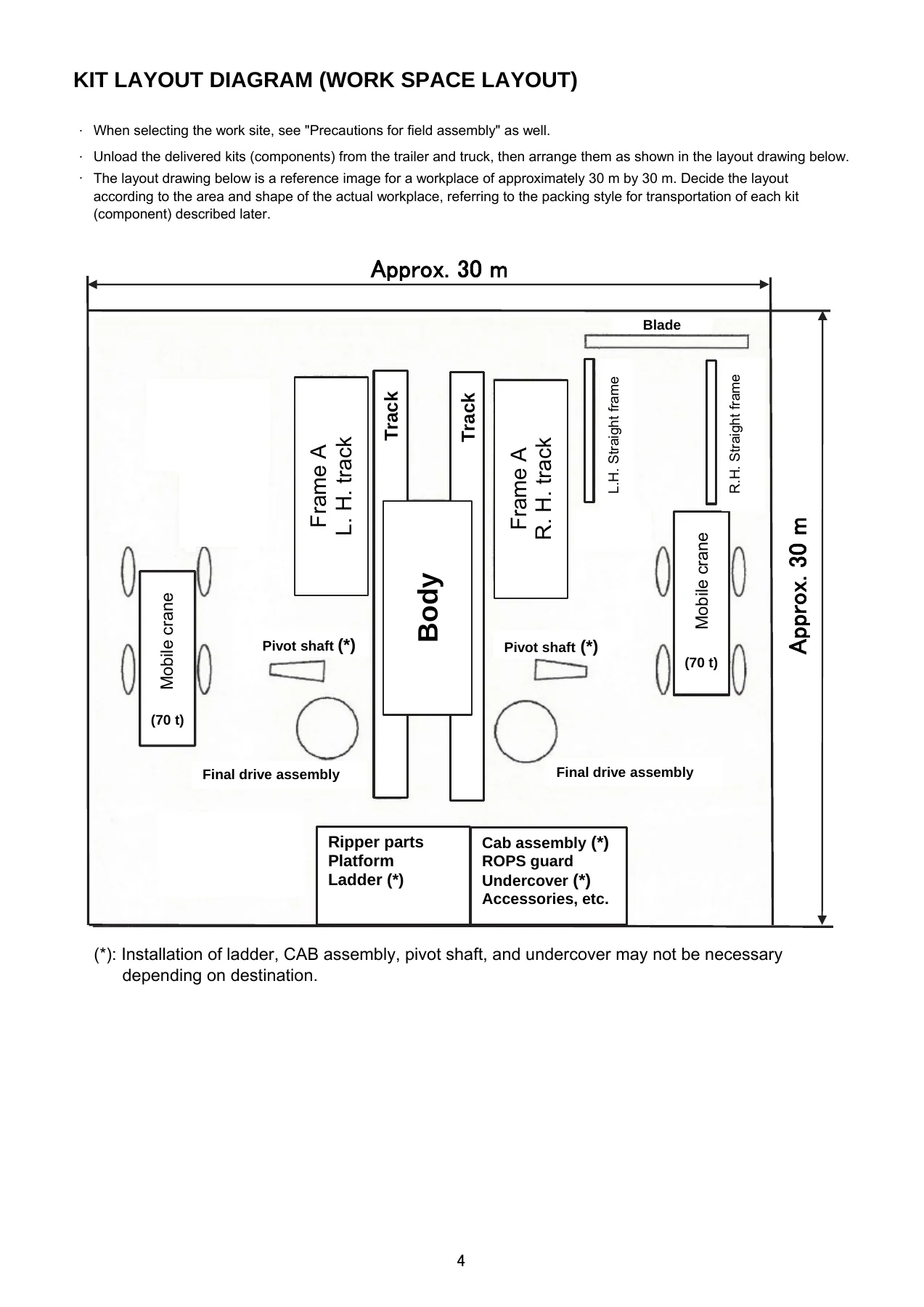
- Kit Layout Diagram (Work Space Layout)
- Packing Style for Transportation
- Machine body
- Track frame assembly
- Full-U blade assembly
- Semi-U blade assembly
- Superdozer blade assembly
- Blade straight frame assembly (L.H. and R.H.)
- Blade tilt cylinder
- Blade lift hydraulic cylinder
- Ripper hydraulic cylinders
- Final drive assembly
- Pivot shaft
- Engine undercover, power train undercover (front and rear)
- Giant ripper beam, arm, and shank assembly
- Multi-shank ripper beam and shank assembly
- Operator’s cab assembly
- ROPS guard
- Platform ladders (L.H., rear, related parts)
- Ladder assemblies
- Counterweight
- Specifications
- Tool List for Field Assembly
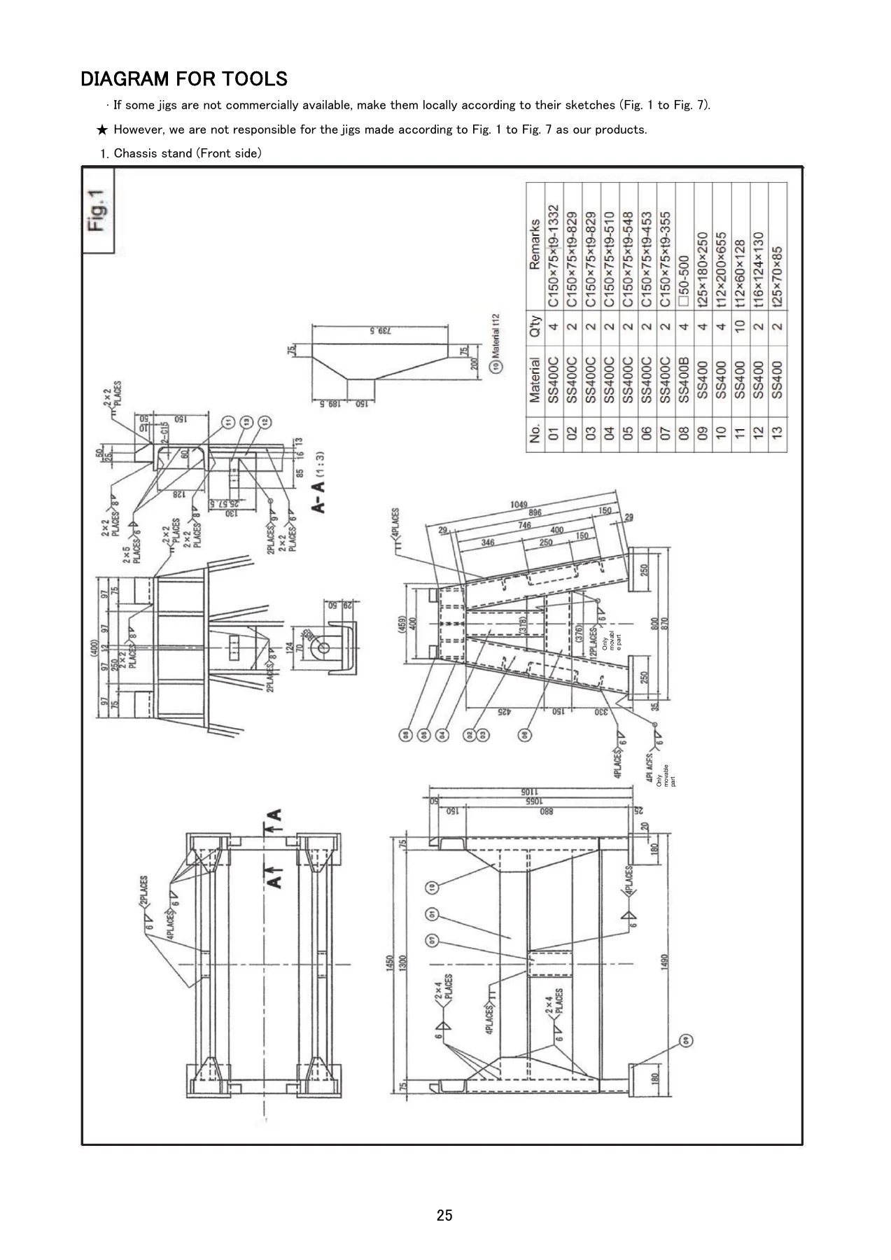
- Diagram for Tools
- Tighten Torque Table
- Coating Materials List
- Selection of Wire Ropes Used for Assembly
- Selection of Nylon Slings Used for Assembly
- Assembly Procedure
- A-1 Installation of track shoe assembly
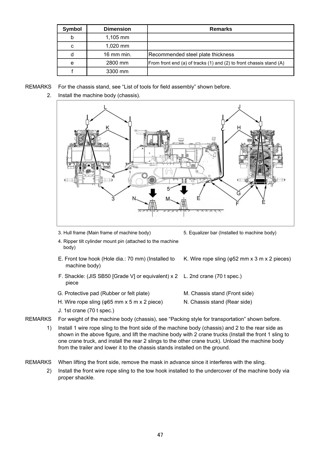
- A-2 Installation of machine body (chassis)
- A-3 Installation of operator’s cab assembly
- A-4 Installation of pivot shaft
- A-5 Installation of final drive assembly
- A-6 Installation of undercover
- A-7 Installation of blade lift hydraulic cylinder
- A-8 Installation of undercarriage -1 and -2
- A-9 Adding oil to pivot chamber
- A-10 Inspection of oil level and coolant level
- A-11 Installation of ripper (1 through 6) and counterweight
- A-12 Installation of trunnion
- A-13 Installation of track
- A-14 Adjusting of track tension
- A-15 Installation of mask
- A-16 / A-17 Handrail and step on right / left side of radiator
- A-18 / A-19 Cab right / left side cover
- A-20 Assembling of blade unit (1 through 5) for semi-U, full-U, and superdozer blades
- A-21 Installation of blade assembly
- A-22 Installation of KOMTRAX antenna
- A-23 Installation of ROPS
- A-24 Installation of engine air intake port hood
- A-25 Installation of pre-cleaner (optional)
- A-26 Installation of engine exhaust pipe
- A-27 Installation of headlamp
- A-28 Installation of giant ripper shank
- A-29 / A-30 Adjustment of blade tilt control angle
- A-31 Blade pitch current value correction
- A-32 Installation of platform (1 through 4)
- A-33 Greasing each part
- A-34 Bleeding air from hydraulic cylinder
- A-35 Bleeding air from work equipment pump and fan pump
- A-36 Installation of quick charge piping (optional)
- A-37 Installation of ladder
- A-38 Installation of ladder for retrofitting
- A-39 Installation of access light and additional work lamp
- Check and Maintenance Procedures After Completion of Assembly
- M-1 Checking machine monitor (1 through 5)
- M-2 Adjustment menu
- M-3 Change of return filter (standard to flushing)
- M-4 Flushing hydraulic circuit and bleeding air from cylinder
- M-5 Change of return filter (flushing to standard)
- M-6 Bleeding air from cylinder
- M-7 How to start operation of KOMTRAX terminal
- M-8 No-injection cranking of engine
- Appendix 1: Installation of Spill Guards
- Field Assembly Inspection Report
- Quick PM
- PM Clinic Service
In total, this manual gives the assembly crew a complete, self-contained reference for turning a shipment of separate kits into a fully operational D475A-8R bulldozer. The assembly procedures are organized so that each step lists the required tools, part numbers, tightening torques, and coating materials, with drawings and photographs to confirm the correct method. The later sections – the inspection report, Quick PM, and PM Clinic – provide the post-assembly verification and performance checks needed before the machine goes to work.
What This Manual Covers for the D475A-8R
The field assembly sequence starts with unloading and arranging the delivered kits on a roughly 30 m by 30 m work site. The supervisor is instructed to hold a safety meeting, confirm protective equipment, inspect slings and tools, and appoint a work leader, crane director, and signal man. The early steps cover spreading the tracks, placing the chassis stands, and lifting the machine body with two 70-ton cranes. From there, the assembler works through pivot shaft installation, final drive mounting, undercover fitment, blade lift cylinder installation, track frame assembly, trunnion, and track installation.
A major portion of the manual is dedicated to the blade and ripper options. Separate procedures are provided for semi-U blades, full-U blades, and superdozer blades, with individual steps for assembling the straight frames, center brace, tilt cylinder, and handrails. Ripper installation is covered across six sub-procedures plus a separate counterweight procedure, ensuring that any D475A-8R configuration delivered to the field can be assembled correctly.
The manual also includes detailed tool and equipment lists for field assembly, including chassis stands, sling jigs A, B, and C, shackle selection tables, pinch bars, torque wrenches, impact wrenches, and wooden blocks. The tightening torque tables cover standard bolts, pipe threads, hydraulic hose connecting nuts, and M39-and-larger socket sizes. The coating materials list documents the liquid adhesives, liquid gaskets, molybdenum disulfide lubricants, greases, primers, and caulking materials used during assembly.
Why the Komatsu D475A-8R Field Assembly Manual Matters
Assembling a D475A-8R in the field is not a job that can be improvised. The machine is large, heavy, and handled with cranes in dangerous postures. Each component has a correct lifting point, a correct tightening torque, and a correct sequence. Using the wrong sling angle, skipping a shim adjustment, or failing to bleed a hydraulic circuit properly can damage the machine, delay the project, or create a safety hazard. This manual gives the assembly team the exact procedures and specifications that Komatsu intends to be followed.
The document also includes the Field Assembly Inspection Report – a check sheet that the assembly team fills in and returns to the inspection section at the Osaka plant. This report covers oil and coolant levels, hydraulic bleeding, monitor display checks, travel and steering operation, blade and ripper functions, and ROPS tightening torque records. The Quick PM section describes how to use the machine monitor Snapshot function to collect diagnostic data under specific operating conditions.
Who This Manual Is For
This Komatsu D475A-8R field assembly manual is written for the work supervisor, work leader, assembly mechanics, crane operators, and field service technicians responsible for putting the machine together after transport. It is also useful for maintenance planners who need to understand how the machine is assembled in order to plan future disassembly, transport, and reassembly. The inspection and PM sections are relevant to service managers and technicians responsible for the machine’s post-assembly acceptance.
Get the Komatsu D475A-8R Field Assembly Manual
This is a complete, 325-page field assembly manual delivered as a PDF. Once the order is placed, the file is available for immediate download – no shipping, no waiting. The manual can be viewed on a laptop, tablet, or smartphone in the workshop or on site, and it can be printed for use as a paper reference. With the full assembly sequence, tool lists, torque tables, and inspection procedures in one document, this manual supports the entire D475A-8R field assembly job from the first crane lift to the final check sheet.
IMAGES PREVIEW


Reviews
There are no reviews yet.