
Komatsu D65EX-16 D65PX-16 D65WX-16 Bulldozer Shop Manual SEN04887-09
Original price was: $39.95.$24.95Current price is: $24.95.
Complete Komatsu shop manual for D65EX-16, D65PX-16 and D65WX-16 bulldozers, serial 80001 and up. Covers engine and cooling, power train, HSS, undercarriage, hydraulics, work equipment, cab, electrical system, testing and adjusting, troubleshooting by failure code, disassembly and assembly, plus hydraulic and electrical diagrams.
Description
Komatsu D65EX-16 D65PX-16 D65WX-16 Bulldozer Shop Manual SEN04887-09
This is the complete Komatsu shop manual for the D65EX-16, D65PX-16 and D65WX-16 bulldozers, covering serial numbers 80001 and up. Published under Form No. SEN04887-09, this 1,573-page document gives technicians and owners the full service documentation for these machines: the SAA6D114E-3 diesel engine mount and cooling system, the complete power train from torque converter through transmission and HSS unit to the final drive, the hydraulic work equipment circuit with CLSS control, the undercarriage and frame, the ROPS cab and its attachments, and the electrical system including monitor, engine control, cooling fan control, electronic steering and KOMTRAX. Every testing, adjusting, troubleshooting, disassembly and assembly procedure that Komatsu published for these models is included, along with the standard service value tables and the hydraulic and electrical diagrams.
File Details
- Manual type: Complete Shop Manual (chassis volume with engine reference)
- Brand: Komatsu
- Models: D65EX-16, D65PX-16, D65WX-16
- Engine: Komatsu SAA6D114E-3 diesel engine
- Serial numbers: D65EX-16 80001 and up; D65PX-16 80001 and up; D65WX-16 80001 and up
- Language: English
- Page count: 1,573 pages
- File format: PDF
- Form No.: SEN04887-09
Chapters Covered
- 00 Index and foreword – composition of shop manual, table of contents
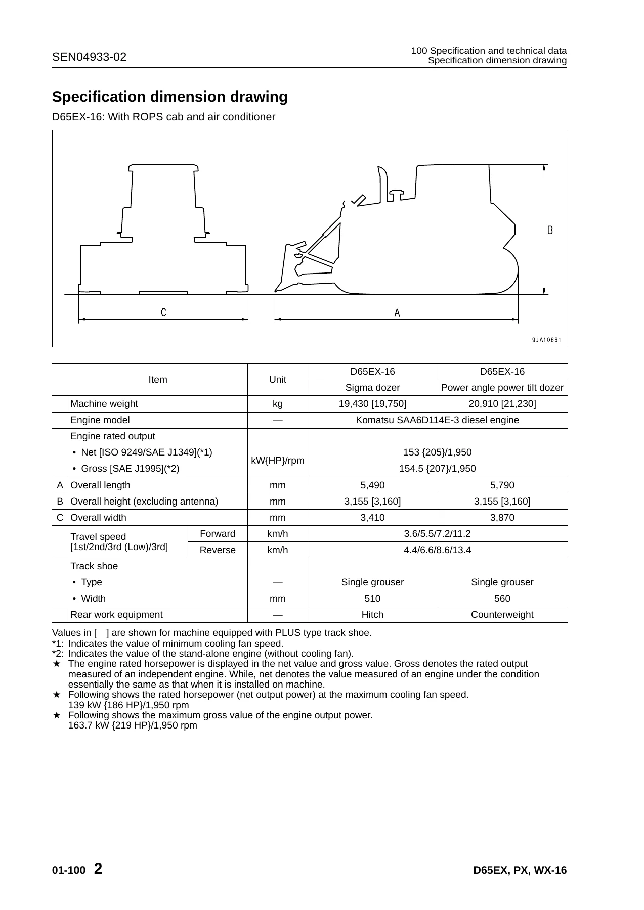
- 01 General – specification and technical data, specification dimension drawing, weight table, table of fuel, coolant and lubricants
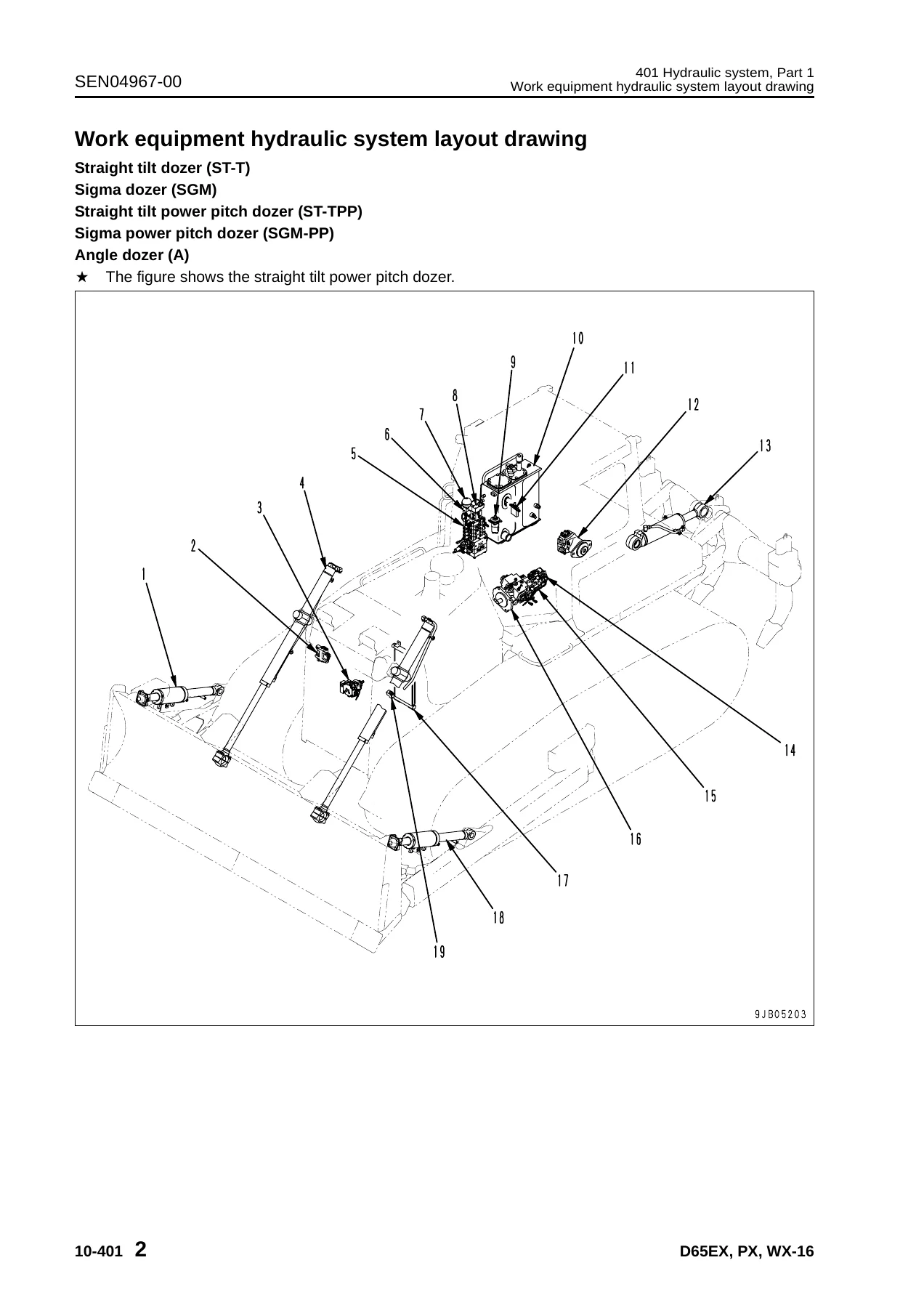
- 10 Structure, function and maintenance standard – Engine and cooling system, Power train Part 1, Power train Part 2, Undercarriage and frame, Hydraulic system Parts 1–3, Work equipment, Cab and its attachments, Electrical system
- 20 Standard value table – standard service value table for engine and for chassis
- 30 Testing and adjusting Parts 1–4 – tools, engine speed, intake air pressure, exhaust temperature and color, valve clearance, compression pressure, blow-by pressure, engine oil pressure, fuel system handling and tests, fuel return and leak amount, air conditioner belt, alternator belt, power train oil pressure, transmission output shaft speed sensor, brake performance and pedal, parking brake lever, idler clearance, sprocket wear, track shoe tension, work equipment and HSS oil pressure, control circuit basic pressure, PPC valve output and play, cylinder leakage and bleeding, fan speed and fan circuit pressure, special functions of machine monitor (EMMS), controller voltage, Pm-Clinic service
- 40 Troubleshooting – failure code table and fuse locations, general information on troubleshooting, troubleshooting by failure code Parts 1–6, electrical system troubleshooting (E-mode), hydraulic and mechanical troubleshooting (H-mode), engine troubleshooting (S-mode)
- 50 Disassembly and assembly – general information, Engine and cooling system, Power train, Undercarriage and frame, Hydraulic system, Work equipment, Cab and its attachments, Electrical system
- 80 Appendix – Air conditioner
- 90 Diagrams and drawings – hydraulic diagrams and drawings, electrical diagrams and drawings
Beyond the chapter list, the manual delivers complete procedure-level detail for these machines. A technician can follow the engine and cooling system removal and installation steps for the fuel supply pump, fuel injectors, cylinder head, radiator, aftercooler, hydraulic oil cooler, power train oil cooler, cooling fan drive, cooling fan motor, coolant preheater and damper. The power train section covers the complete unit removal and separation into PTO, torque converter, transmission and HSS assembly, then walks through each sub-assembly including the HSS assembly with bevel gear shaft, brake and final drive in both conventional and planetary-gear-inside-sprocket configurations. The undercarriage chapter covers track frame, idler, recoil spring, track roller, carrier roller, sprocket, track shoe and pivot shaft and equalizer bar work. The hydraulic system chapter covers the hydraulic tank, control valve, blade lift and tilt PPC valve, ripper PPC valve, HSS and cooling fan pump, power train and lubrication pump, scavenging pump, HSS motor and hydraulic cylinders.
Systems and Components Covered in Depth
The manual’s coverage of engine and cooling includes the engine mount, cooling system, cooling fan pump (LPV30), cooling fan motor (LMF28), and the coolant preheater used on subextremely cold weather specification machines, with the timing charts, electrical circuit diagram and component function descriptions. The power train section explains the HSS system (Hydrostatic Steering System), the damper, universal joint, torque converter with lockup clutch, PTO, the planetary transmission with its disc clutches and control valve, the ECMV (Electronic Control Modulation Valve) for F, R, 1st, 2nd, 3rd and lockup clutches, the main relief and torque converter relief valve, the transmission lubrication relief valve, the bevel gear shaft, HSS and brake, brake valve and final drive. The electrical system section covers the monitor system with display and switch functions, engine control system, cooling system control system, electronic steering control system, KOMTRAX system and terminal, plus the system components and sensor descriptions with their input and output signals.
Testing, Adjusting and Troubleshooting
The testing and adjusting chapters list every special tool by part number and symbol, then walk through the measurement of engine speed (low idle, high idle, decelerator pedal speed and torque converter stall speed), intake air boost pressure, exhaust temperature, exhaust gas color, valve clearance, compression pressure, blow-up pressure and engine oil pressure. The fuel system section explains safe handling, releasing residual pressure, testing fuel pressure in the negative pressure and low-pressure circuits, testing fuel return and leak amount, bleeding air and testing for leakage. Chassis-side testing covers power train oil pressure measurement at every port (brake, torque converter inlet and outlet, transmission main relief, F, R, 1st, 2nd, 3rd and lockup clutch), transmission output shaft speed sensor adjustment, brake performance, brake pedal, parking brake lever, idler clearance, track shoe tension, work equipment and HSS oil pressure, control circuit basic pressure, PPC valve output pressure, cylinder leakage, fan speed and fan circuit oil pressure.
Failure Code Diagnostics and Monitor Functions
The troubleshooting section is one of the most valuable parts of this document. It starts with the failure code table and fuse locations, then the general information on troubleshooting including the checks before troubleshooting and the classification and procedures for troubleshooting. Troubleshooting by failure code is split into six parts that cover transmission clutch fill codes, engine controller codes (CA series) for the common rail fuel injection system, sensor supply voltages, injector drive circuits, rail pressure codes, grid heater relay codes, and machine monitor and PT controller codes (D-series) for battery relay drive, neutral relay, back-up alarm relay, GPS antenna, CAN disconnection, controller abnormalities, source voltage reductions, type select signal, shift switches, parking lever switch, work equipment knob switches, oil temperature and pressure sensors, fuel control dial, steering and F/R lever potentiometers, pitch angle sensor, transmission output speed sensor, pitch selector solenoid, fan reverse EPC, HSS EPC1 and EPC2, fan pump solenoid, TVC solenoid, lockup and clutch ECMVs, and work equipment lock solenoid. The E-mode chapter covers electrical system troubleshooting from E-1 through E-26 including starting motor, preheater, machine monitor display, gauges, mode switching, buzzer, horn, back-up alarm, head and rear lamps, windshield wipers, window washers and the KOMTRAX system. The H-mode chapter covers hydraulic and mechanical troubleshooting from H-1 through H-18 for travel power, speed, steering, brake, power train oil overheat, HSS noise, work equipment speed, and hydraulic drift. The S-mode chapter covers engine troubleshooting from S-1 through S-16 covering starting, pick-up, stopping, rotation, output, exhaust smoke, oil consumption, contamination, fuel consumption, coolant issues, oil pressure, oil level, overheating, abnormal noise and vibration.
Why Correct Procedures and Specifications Matter
On a machine like the D65, incorrect clutch pressures, wrong torque values on the final drive mounting bolts or the transmission main relief, or a misadjusted track shoe tension can quickly turn a repair into a repeat failure. The standard service value tables in the manual give the exact standard values, permissible values and service limits for engine and chassis so the technician can judge whether a part is reusable. The testing and adjusting chapters give the standard clearances, adjustment ranges, and the correct sequence for hydraulic drift checks, PPC valve play adjustment and brake pedal adjustment. The disassembly and assembly chapters give the torque values for every critical fastener group, the coating materials for gaskets and O-rings, and the special tools required to avoid damaging seals, bearings and pistons. Having this information in one searchable document rather than scattered across service bulletins is what makes the difference between a one-time repair and a recurring problem.
IMAGES PREVIEW
Instant PDF Delivery
This Komatsu D65EX-16 D65PX-16 D65WX-16 bulldozer shop manual is delivered as an instant-download PDF. There is no shipping, no waiting for a disc, and no physical item to keep track of. The file can be opened on any laptop, tablet or smartphone, printed for the workshop, and searched for the failure code, torque value or adjustment you need at the moment you need it. Whether you are a Komatsu technician working on a D65EX-16, a D65PX-16 or a D65WX-16, a fleet owner keeping a D65 running, or an independent shop servicing one for a customer, this manual gives you the same service information Komatsu published for these serial numbers 80001 and up so you can diagnose, repair and reassemble with confidence.
Reviews
There are no reviews yet.