
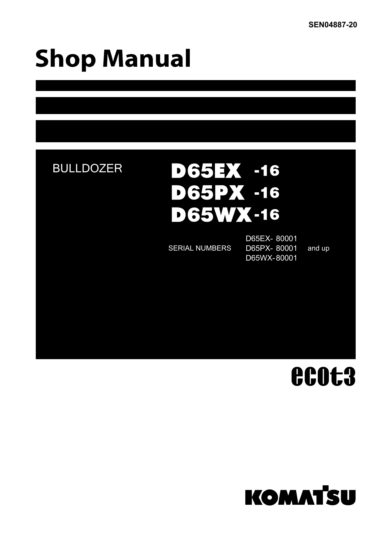
Komatsu D65EX-16 D65PX-16 D65WX-16 Bulldozer Shop Manual SEN04887-20
Original price was: $39.95.$24.95Current price is: $24.95.
Complete 1632-page Komatsu shop manual for D65EX-16, D65PX-16 and D65WX-16 bulldozers (S/N 80001 and up). Full engine, power train, undercarriage, hydraulic, electrical, testing and troubleshooting coverage for professional service work.
Description
Komatsu D65EX-16, D65PX-16, D65WX-16 Bulldozer Shop Manual SEN04887-20
This is the complete Komatsu shop manual for the D65EX-16, D65PX-16 and D65WX-16 bulldozers, covering machines from serial number 80001 and up. Form number SEN04887-20, the same documentation set Komatsu service technicians work from in the workshop. Everything is here: engine and cooling system, power train, undercarriage and frame, hydraulic systems, work equipment, cab, electrical system, plus the full testing, adjusting, troubleshooting and disassembly/assembly procedures.
File Details
- Manual type: Shop Manual (Chassis and Engine coverage)
- Brand: Komatsu
- Models covered: D65EX-16, D65PX-16, D65WX-16
- Serial number range: 80001 and up
- Document number: SEN04887-20
- Language: English
- Page count: 1632
- File format: PDF
- Publication date shown: 2024-10
Chapters Covered
- 00 Index and foreword – Composition of shop manual, safety notice, how to read the shop manual, explanation of terms for maintenance standard, handling of electric equipment and hydraulic components, handling of connectors newly used for engines, how to read electric wire code, precautions when carrying out operation, push-pull type coupler disassembly/connection, standard tightening torque table, conversion table
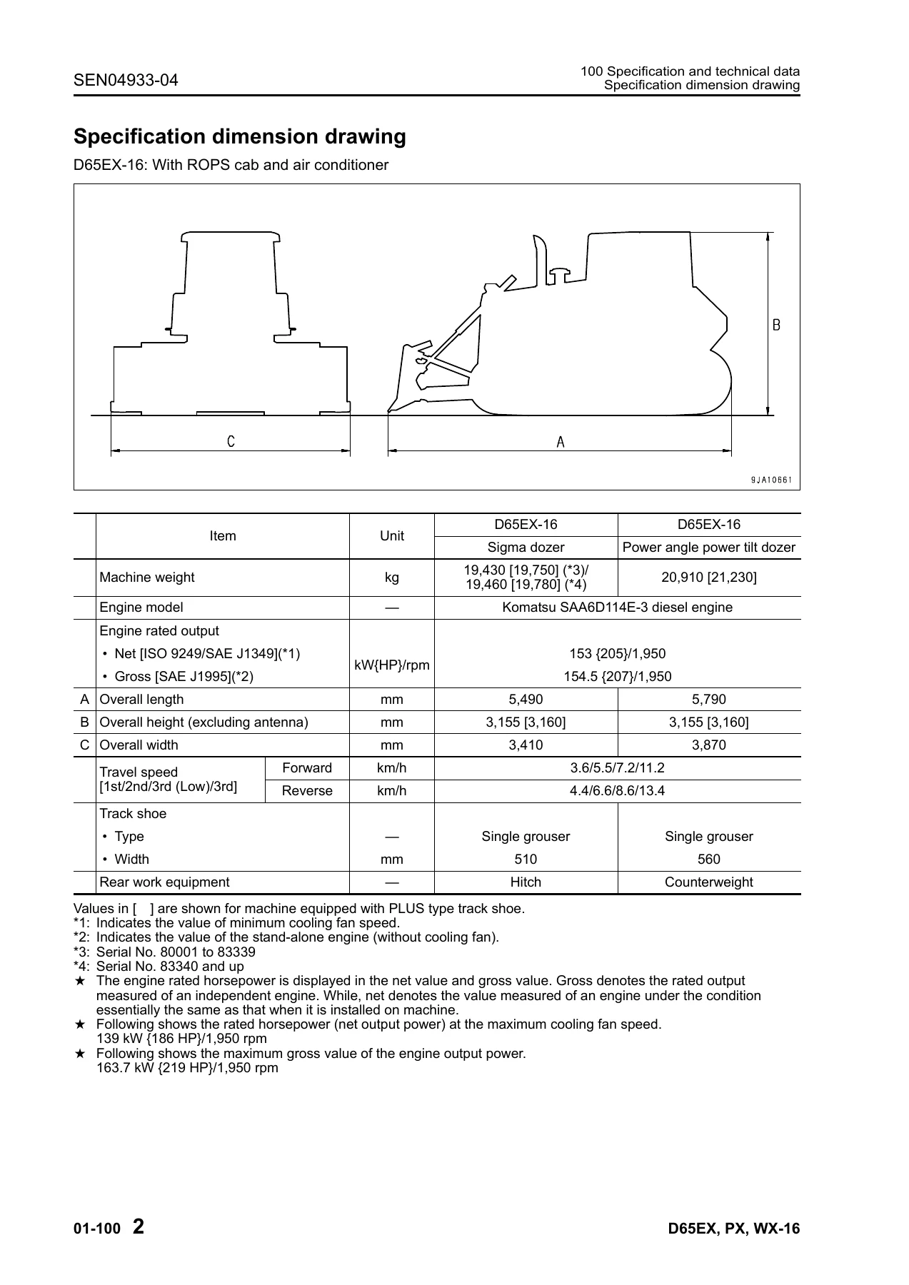
- 01 General – Specification dimension drawings, machine specifications, weight table, fuel/coolant/lubricants table
- 10 Structure, function and maintenance standard
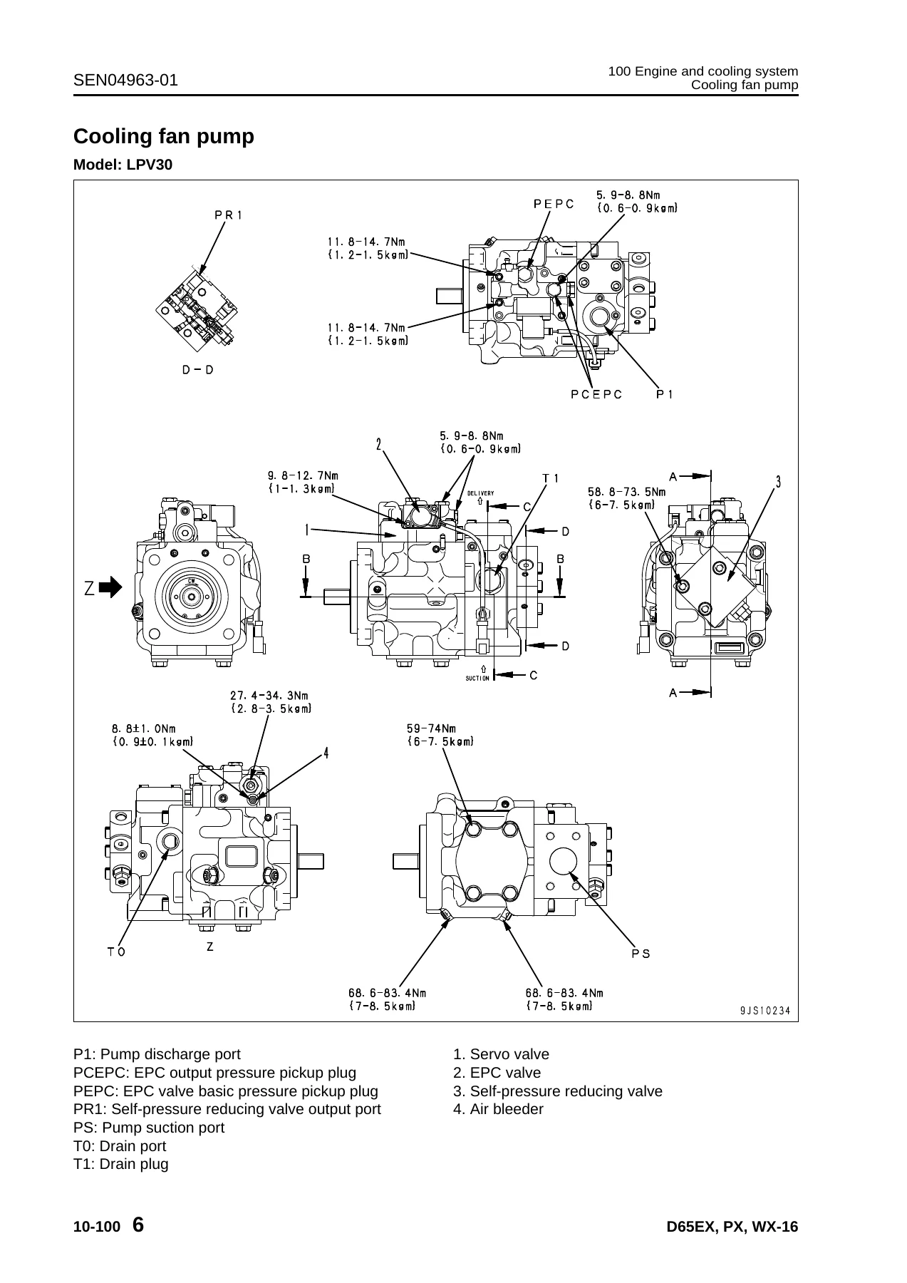
- 100 Engine and cooling system – engine mount, cooling system, cooling fan pump, cooling fan motor, coolant preheater
- 201 Power train Part 1 – power train layout, HSS system, hydraulic piping, transmission/steering/brake control, damper, universal joint, torque converter and PTO, transmission, transmission control valve, ECMV, main relief and torque converter relief valve, transmission lubrication relief valve
- 202 Power train Part 2 – bevel gear shaft, HSS, brake, brake valve, final drive, final drive with planetary gear inside sprocket
- 300 Undercarriage and frame – main frame, suspension, track frame and idler cushion, idler, track roller, carrier roller, sprocket, track shoe
- 401 Hydraulic system Part 1 – work equipment hydraulic layout, hydraulic tank and filter, scavenging pump, power train and steering lubrication pump, HSS pump, HSS motor
- 402 Hydraulic system Part 2 – control valve, CLSS, function and operation of each valve
- 403 Hydraulic system Part 3 – PPC valve (blade lift/tilt), PPC valve (ripper), electric lever (steering), quick drop valve, work equipment lock solenoid valve, pitch selector solenoid valve, hydraulic oil cooler bypass valve, accumulator
- 500 Work equipment – blade, cutting edge and end bit, ripper (multi shank/single shank), hydraulic cylinder, piston valve
- 600 Cab and attachments – cab mount, cab, subextremely cold spec cab, FRP canopy mount, FRP canopy
- 700 Electrical system – monitor system, engine control system, cooling system control, electronic steering control system, KOMTRAX system, system components, sensors
- 20 Standard value table – Standard service values for engine and chassis (speeds, pressures, clearances, tolerances, torque values, drift limits)
- 30 Testing and adjusting
- Part 1 – engine speed, intake air/boost pressure, exhaust temperature and color, valve clearance, compression pressure, blow-by, engine oil pressure, fuel system pressure/return/leak, belt tension, fuel control dial and decelerator pedal
- Part 2 – power train oil pressure, transmission output speed sensor, brake performance, brake pedal, parking brake lever, idler clearance, sprocket wear, track shoe tension, work equipment and HSS pressure, control circuit pressure, PPC valve output, PPC valve play, cylinder leakage, hydraulic drift, work equipment lock lever, fan speed, fan circuit pressure, straight tilt dozer adjustment, blade center ball, operator’s cab
- Part 3 – Special functions of machine monitor (EMMS), Monitoring, Abnormality Record, Maintenance Record, Maintenance Mode Change, Phone Number Entry, Default, Adjustment, Pm Clinic, Cylinder Cut-Out, No Injection, Fuel Consumption, KOMTRAX Settings, Service Message
- Part 4 – Controller high-voltage circuit handling, adjustment after controller replacement, preparation for electrical troubleshooting, diode inspection, Pm-Clinic service
- 40 Troubleshooting
- Failure code table and fuse locations
- General troubleshooting info – points to remember, procedure, checks before troubleshooting, classification, symptom tables, connector list and connection tables
- Troubleshooting by failure code Parts 1-6 (transmission clutch, torque converter, engine, sensor, injector, ECMV, relay, solenoid and other electrical codes)
- Electrical system troubleshooting (E-mode) – E-1 to E-26 covering starting, preheater, monitor, gauges, switches, lamps, wipers, washers, KOMTRAX
- Hydraulic and mechanical troubleshooting (H-mode) – H-1 to H-18 covering travel, steering, brake, overheating, work equipment and drift
- Engine troubleshooting (S-mode) – S-1 to S-16 starting, stopping, power, smoke, oil/fuel/coolant consumption, noise, vibration
- 50 Disassembly and assembly
- General info, coating materials, special tool list and sketches
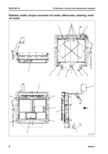
- Engine and cooling system – fuel supply pump, fuel injector, cylinder head, radiator, aftercooler, hydraulic oil cooler, power train oil cooler, cooling fan drive, cooling fan motor, coolant preheater, engine assembly, damper, front/rear oil seal, engine hood, fuel tank
- Power train – power train unit, PTO, torque converter, transmission, HSS, final drive (standard and planetary-in-sprocket)
- Undercarriage and frame – track frame, idler, recoil spring, track roller, carrier roller, track shoe, pivot shaft, equalizer bar
- Hydraulic system – hydraulic tank, control valve, blade PPC valve, ripper PPC valve, HSS and cooling fan pump, power train and lubrication pump, scavenging pump, HSS motor, hydraulic cylinder
- Work equipment – blade, ripper
- Cab and attachments – ROPS cab, FRP canopy, floor frame, cab glass, air conditioner unit, air conditioner compressor
- Electrical system – monitor panel, engine controller, power train controller, KOMTRAX terminal
- 80 Appendix – Air conditioner precautions, structure and function, refrigeration cycle, air conditioner unit, control plate, compressor, condenser, receiver drier, testing and troubleshooting, electrical troubleshooting, gauge pressure troubleshooting, service tool connection, compressor oil handling
- 90 Diagrams and drawings – Hydraulic diagrams and drawings (power train hydraulic circuit, work equipment hydraulic circuit including ST-T, SGM, PAT, ST-TPP, SGM-PP and trimming versions), Electrical diagrams and drawings (cab specification, subextremely cold weather spec, sand terrain spec, FRP canopy spec)
This is a working dealer-level shop manual, not a quick-reference guide. It runs 1632 pages and covers the D65EX-16, D65PX-16 and D65WX-16 from the ground up. The structure, function and maintenance standard chapters explain how each system is built and how it works, then give the wear limits, clearances and standard values you need to decide whether a part is reusable or needs replacing. The testing and adjusting chapter gives you the exact measurement procedures, pressures and speeds, and the troubleshooting chapters give you failure-code-driven diagnostics for electrical, hydraulic, mechanical and engine problems. The disassembly and assembly chapters walk you through the removal, tear-down, inspection, reassembly and installation of every major unit, with tightening torques, special tools, coating materials and weights. Whether you are rebuilding a transmission, resealing a hydraulic cylinder, diagnosing a CAN communication fault, adjusting blade play or setting final drive preload, the procedure and the numbers are here.
What This Manual Lets You Do
- Run the same diagnostic procedures a Komatsu dealer technician uses, including failure code troubleshooting for the engine controller, power train controller and machine monitor
- Test and adjust engine speed, boost pressure, compression, blow-by, oil pressure, fuel pressure and return flow
- Measure and adjust power train oil pressures, HSS pressures, work equipment pressures and control circuit pressures
- Disassemble and reassemble the torque converter, transmission, HSS unit, final drive, bevel gear shaft, brakes, undercarriage components and hydraulic cylinders with correct torques and tools
- Interpret hydraulic circuit diagrams and electrical circuit diagrams for cab, canopy and cold-weather specifications
- Navigate the machine monitor service mode, including adjustment codes, monitoring codes, abnormality records and maintenance settings
- Service the air conditioner system, including refrigerant handling, self-diagnosis, sensor testing and gauge pressure troubleshooting
- Use the standard value tables to judge whether engine, chassis, undercarriage and hydraulic parts are within specification
- Identify the special tools and coating materials specified for each job
Having the correct procedures and specifications matters. A transmission rebuilt with the wrong clutch clearance, a final drive set to the wrong preload, a hydraulic cylinder assembled with the wrong torque or a brake adjusted to the wrong pressure will not last and may fail again quickly. This manual gives you the exact sequence, the exact measurement and the exact value, so the job is done right the first time.
IMAGES PREVIEW
Delivered as an instant PDF download, no shipping and no waiting. The file works on any device that reads PDFs, and you can print the pages you need for the workshop. Keep it on the laptop in the service truck, on the tablet at the bench or on the shop computer.
Reviews
There are no reviews yet.