
Komatsu GD555-3C Motor Grader Parts Book KEPB074401 — Serial B15001 & Up PDF
Original price was: $59.95.$39.95Current price is: $39.95.
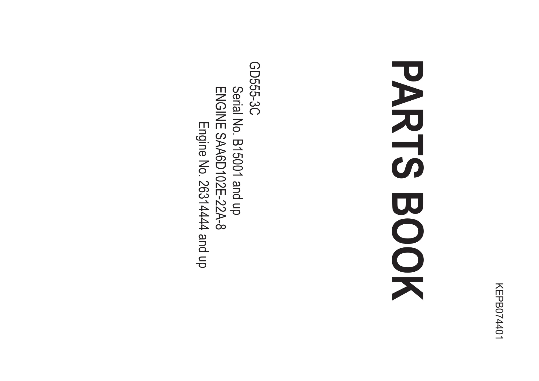
Complete Komatsu GD555-3C motor grader parts book, document KEPB074401. Covers serial B15001 and up, engine SAA6D102E-22A-8 from 26314444 and up. Full exploded-view illustrations with part numbers for engine, transmission, hydraulics, electrical, operator’s cab, work equipment and more. Instant PDF download.
Description
Komatsu GD555-3C Parts Book — KEPB074401
This is the complete Komatsu GD555-3C motor grader parts book, identified by document number KEPB074401. It covers machines from serial number B15001 and up, powered by the SAA6D102E-22A-8 engine from serial number 26314444 and up. Every assembly on the machine is broken down into exploded-view illustrations with corresponding part numbers, descriptions, and quantities, giving you the exact information needed to identify and order the right components.
File Details
- Manual Type: Parts Book
- Brand: Komatsu
- Model: GD555-3C
- Engine Model: SAA6D102E-22A-8
- Machine Serial Number: B15001 and up
- Engine Serial Number: 26314444 and up
- Document Number: KEPB074401
- Language: English (with foreword sections in French, Arabic, Russian, and Chinese)
- File Format: PDF
- Page Count: 500+ pages
Chapters Covered
The parts book is divided into the following major sections:
- AA — Engine
- B0 — Engine Related Parts
- C0 — Cooling System
- D0 — Fuel Tank and Related Parts
- E0 — Electrical System
- F0 — Transmission
- J0 — Frame and Related Parts
- H0 — Hydraulic System
- K0 — Operator’s Compartment and Control System
- M0 — Guard
- N0 — Circle Motor and Piping
- S0 — Rim and Tires
- T0 — Work Equipment
- U0 — Marks and Plates
- V0 — Accessory and Tool
- Y0 — Service Kit and Component Parts
- ZZ — Numerical Index
AA — Engine
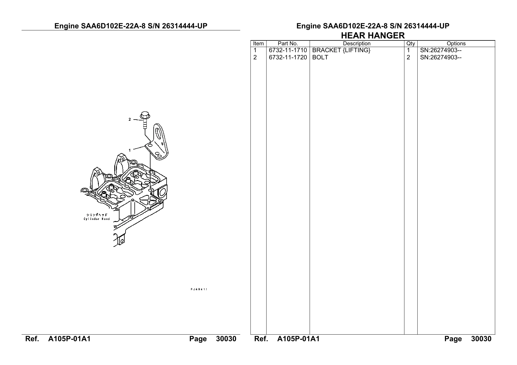
The largest section, covering the complete SAA6D102E-22A-8 engine. Includes exploded-view illustrations and part listings for the cylinder head, cylinder block, front cover, camfollower cover, breather hose, oil pan and suction tube, oil drain tube, oil level gauge, flywheel housing, flywheel, engine front support, crankshaft, damper, piston, rocker arm, tappet, camshaft, front gear train cover, fan pulley, tachometer adapter, under plate, oil pump, oil cooler and oil filter, fuel injection pump with all internal components, boost tube, fuel inlet and outlet joints, fuel injection mounting, fuel filter, fuel piping, injection nozzle, fuel joint, stop solenoid, water connector, water pump, fan drive pulley, cooling fan, fan pilot spacer, alternator, belt tensioner, alternator mounting and cover, starting motor, starting motor mounting, wiring harness clips, and repair parts for the cylinder head, cylinder block, crankshaft, and piston. Also includes the cylinder head gasket kit, cylinder block gasket, caution plate, timer, air cleaner, and muffler.
B0 — Engine Related Parts
Covers the engine mounting parts, engine accessories including damper, remote drain, electrical relay, and accelerator control. Documents the air intake system with air cleaner, inner parts, screen cap and band, mounting parts, piping, rain cap, and intake extension. Includes the exhaust system with exhaust pipe and safety guard.
C0 — Cooling System
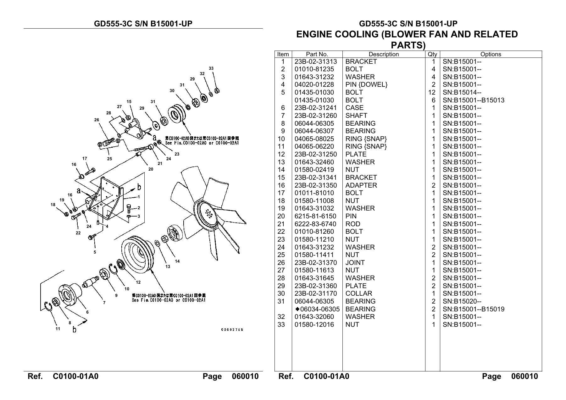
Provides exploded views for the engine cooling system including the blower fan and related parts, fan pulley and V-belt, radiator and mounting parts, radiator piping, sub-tank and piping, and fan guard.
D0 — Fuel Tank and Related Parts
Documents the fuel tank, hydraulic tank and mounting parts, and fuel piping with water separator.
E0 — Electrical System
Includes the battery, fuse and relay box, battery holder, battery wiring, front frame harness with and without blade accumulator, rear harness with sensor and back-up alarm, wiring harnesses for torque converter oil temperature, instrument panel with torque converter temperature gauge, head lamp and turn signal lamp for USA and cab configurations, rear combination lamp, front work lamp, rear work lamp, front and rear work lamps, beacon lamp, horn, license plate lamp, and all associated relays, fuses, and connectors.
F0 — Transmission
Covers the drive shaft assembly with cross pin, yoke shaft, grease fittings, and snap rings. Includes the transmission case, forward low and reverse clutch, forward high and 1st clutch, 2nd and 3rd clutch, 4th clutch, output section, P.T.O. and idler, main relief valve, L/C valve, valve mounting, control valve, control valve mounting, transmission piping, accessories, speed meter, torque converter bare, drive case, and P.T.O.
J0 — Frame and Related Parts
Documents the front frame and mounting pin (with and without scarifier), rear frame and mounting pin, hinge pin for front and rear frame, steering cylinder, remote grease lines, and leaning cylinder.
H0 — Hydraulic System
The largest system section, covering the hydraulic tank with accessory components and drain piping, main control valve with and without scarifier, hydraulic pump with differential lock type, steering piping, accumulator charger valve with inner parts, floor valve, parking and brake control valve with inner parts, valve for hydraulic piping, pilot check valves for leaning, articulate, drawbar shift, blade shift, and ripper circuits, swivel joint, and all hydraulic piping circuits including tank to pump, pump to valve, return line, L.S. piping, connector circuits, brake line, differential piping, ripper piping, bank cylinder line, blade side shift cylinder line, blade lift cylinder line, drawbar side shift cylinder line, cylinder line, articulate cylinder line, blade accumulator line, power tilt cylinder line, scarifier line, and transmission cooling.
K0 — Operator’s Compartment and Control System
Includes the operator’s seat with suspension cover, seat belts in 2-point configurations with 51mm and 78mm widths, operator’s cab frame and glass, cab exterior and interior parts, cab harness, cab seal and mounting parts, rear view mirror, floor mat, window washer with 1-tank and 2-tanks type, air conditioner equipment and mounting parts, air conditioner piping and heater piping, platform, work equipment control levers with and without ripper or scarifier, accelerator and inching pedals, steering post cover, steering post, valve control lever, platform covers, console box, accelerator lever, operator’s seat brackets, brake pedal, steering wheel and steering valve, steering valve piping, stop lamp and service meter, floor harness, console box electrical system, air conditioner control panel and unit, air conditioner duct, elbow for brake valve, engine accessory accelerator control, floor float electric with blade float and diff lock, brake accumulator and slack adjuster, slack adjuster inner parts, brake piping, brake pedal piping, and elbow for brake valve and slack adjuster.
M0 — Guard
Covers the engine hood and radiator guard, side panel for engine hood, buffer plate for engine hood, floor cover and front frame side cover with and without scarifier, platform mounting, transmission under guard, tool box, ladder and side step, front weight, pusher weight, and rear weight.
N0 — Circle Motor and Piping
Illustrates the hydraulic piping for the circle revolution motor line.
S0 — Rim and Tires
Provides complete exploded views of the rim and tire assemblies in the following sizes: 17.5-25-12PR (L2/G2), 17.5-R25, 14.00-24-12PR, 13.00-24-10PR, and 13.00-24-12PR. Includes spare tire options, O-rings, valve stems, cores, seats, adapters, caps, bolts, and washers.
T0 — Work Equipment
Covers the drawbar and circle support, blade lifter with all bushings, seals, and mounting hardware, blade in 3.7M and 4.3M widths with cutting edges and bolts, circle support mounting parts with adjusters, guides, shims, and bushings, ripper with brackets, links, pins, supports, rods, and shanks, ripper shank additional 2-shanks type, circle revolving with slip clutch in two parts, blade lift cylinder, blade shift cylinder, power tilt cylinder, drawbar shift cylinder, scarifier cylinder, ripper cylinder, articulate cylinder, scarifier fixed rod type with arms, pins, and rods, and scarifier shank tooth with shanks, teeth, tools, wedges, and pins.
U0 — Marks and Plates
Documents all safety plates, instruction plates, operating plates, caution plates, name plates, and machine identification marks used on the GD555-3C, including the Komatsu mark, Galeo mark, GD555 model mark, oil chart, and various safety decals for Brazil specification.
V0 — Accessory and Tool
Lists the tool bag, wrench set, wrenches, filter wrench, socket wrench set, screwdriver, pliers, hammer, thickness gauge, bar, tire gauge, grease pump and cartridge, leaning lock bolt, and special wrench.
Y0 — Service Kit and Component Parts
Provides detailed exploded views and part listings for the service kit, main pump in six parts, gear pump single and tandem with inner parts, blade lift cylinder, blade shift cylinder, drawbar shift cylinder, power tilt cylinder, scarifier cylinder, rear ripper cylinder, steering cylinder, leaning cylinder, articulate cylinder, accumulator for brake and blade, control valve in 4-spool and 5-spool configurations for L.H. and R.H. with scarifier, LS reducing valve, steering valve, and air conditioner unit in multiple parts.
ZZ — Numerical Index
A complete numerical index of every part number in the book, organized in ascending order, with cross-references to the figure number and page where each part is illustrated. This is the fastest way to locate a specific part number when you already know what you need.
Why This Parts Book Matters
When you’re maintaining or repairing a Komatsu GD555-3C motor grader, ordering the wrong part costs time and money. This parts book eliminates the guesswork. Every exploded-view illustration is indexed with the exact part number and quantity, so you can identify components accurately before placing an order. Whether you’re rebuilding the engine, servicing the transmission, repairing the hydraulic system, or replacing worn undercarriage components, the correct part numbers are right here.
The book covers the complete machine — from engine internals and fuel system components to the operator’s cab, work equipment, and even the decals. The numerical index at the back lets you cross-reference any part number back to its illustration and page location. This is the same reference material used by Komatsu parts professionals to identify and order components.
IMAGES PREVIEW
Instant PDF Delivery — No Shipping, No Waiting
This parts book is delivered as a high-quality PDF file that you can download immediately after payment. No shipping charges, no waiting for a physical book to arrive. The file works on any device — laptop, desktop, tablet, or smartphone — and you can print the pages you need for the shop floor. Whether you’re at the dealership, in the field, or in your workshop, the complete Komatsu GD555-3C Parts Book is always at your fingertips.

Reviews
There are no reviews yet.