
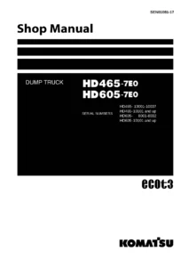
Komatsu HD465-7E0 & HD605-7E0 Dump Truck Shop Manual SEN01081-08 – Complete PDF Service & Repair Workshop Manual
Original price was: $79.95.$49.95Current price is: $49.95.
The complete Komatsu HD465-7E0 and HD605-7E0 Dump Truck Shop Manual (Form No. SEN01081-08), covering specifications, structure and function, standard values, testing and adjusting, troubleshooting, disassembly and assembly, and full hydraulic and electrical diagrams. Instant PDF download.
Description
Komatsu HD465-7E0 & HD605-7E0 Dump Truck Shop Manual – SEN01081-08
This is the complete Komatsu Shop Manual for the HD465-7E0 and HD605-7E0 dump trucks, issued under Form No. SEN01081-08. It is the same shop manual used by professional technicians to service, diagnose, repair, and overhaul these rigid-frame haul trucks. Whether you are adjusting a transmission ECMV, troubleshooting a failure code, measuring suspension cylinder gas pressure, or overhauling a final drive, the procedures, values, and diagrams in this manual are the ones you need.
The document covers all major systems in exhaustive detail: engine and cooling, torque converter and transmission, axles and final drives, steering, brakes and retarder, suspension, hydraulic hoist and steering circuits, the dump body, cab and attachments, and the full electrical system including machine monitor, transmission controller, retarder controller, VHMS, payload meter, and ABS/ASR (where equipped).
File Details
- Manual type: Shop Manual (Service & Repair)
- Brand: Komatsu
- Models covered: HD465-7E0, HD605-7E0
- Language: English
- File format: PDF
- Page count: 1,613 pages
- Document number: SEN01081-08
- Publication date: 2008
Chapters Covered
- 00 Index and foreword
- 01 Specification
- 10 Structure, function and maintenance standard
- 20 Standard value table
- 30 Testing and adjusting
- 40 Troubleshooting
- 50 Disassembly and assembly
- 90 Diagrams and drawings
00 – Index and Foreword
Contains the shop manual composition table, safety notices, general precautions, handling instructions for electric equipment and hydraulic components, connector handling for engines, how to read electric wire codes, precautions for removal and installation, push-pull coupler procedures, standard tightening torque tables, and conversion tables. This section establishes the conventions and safety framework used throughout the rest of the manual.
01 – Specification
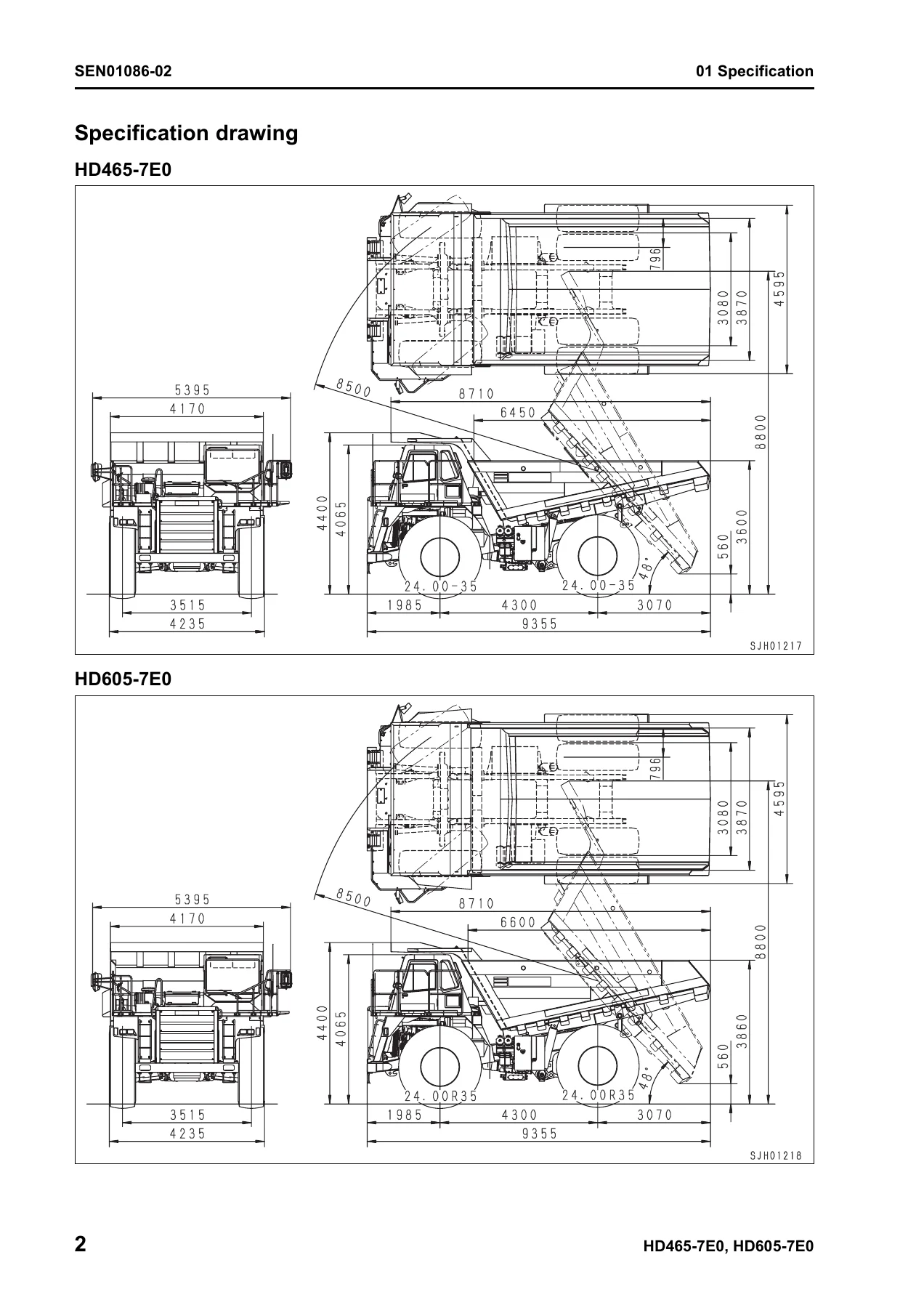
Provides the specification drawing and full technical specifications for both the HD465-7E0 and HD605-7E0, including weight tables (empty, max. load, gross, and weight distribution), performance figures, dimensions, engine data (KOMATSU SAA6D170E-5), power train details, tire sizes, brake system specs, hydraulic pump and cylinder data, and a comprehensive fuel, coolant and lubricants chart with ambient temperature ranges and specified capacities for every reservoir.
10 – Structure, Function and Maintenance Standard
The largest chapter, broken into focused sub-sections covering every major system. It explains how components work and gives maintenance standard values (wear limits, clearances, tolerances, spring data, backlash, etc.) with remedies. Coverage includes:
- Engine and cooling system – radiator, torque converter oil cooler, aftercooler, work equipment oil cooler, fuel cooler, brake oil cooler, output shaft
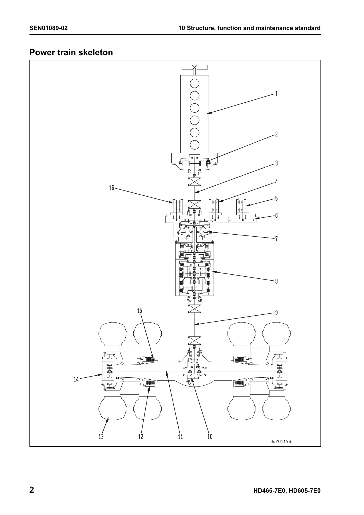
- Power train Part 1 – power train skeleton, drive shafts, torque converter and transmission hydraulic piping, brake cooling oil control valve (BCV), torque converter and torque converter valve, transmission, transmission control valve, and ECMV
- Power train Part 2 – axles, differential, final drive, wheels
- Steering system – steering column, steering linkage
- Brake system – brake piping, brake valve, secondary brake valve, relay valve, front brake off valve, accumulator charge valve, accumulator, slack adjuster, brake, parking brake solenoid valve
- Undercarriage and frame – suspension (front and rear), A-frame, radius rods
- Hydraulic system – steering and hoist hydraulic piping, dump body control, hydraulic tank, steering valve, crossover relief valve, steering cylinder, steering control valve, hoist valve, EPC valve, hoist cylinder, hydraulic pump
- Work equipment (Body) – auto greasing system
- Cab and its attachments – ROPS cab, air conditioner, rear view monitor
- Electrical system Parts 1–4 – machine monitor system, automatic shift control system, transmission controller, automatic emergency steering system, automatic suspension system, retarder control system, payload meter (card type), VHMS controller, sensors and switches
20 – Standard Value Table
Contains the standard service value tables for the engine and for the machine. Engine values include high idle, low idle, rated speed, intake air pressure (boost pressure), exhaust temperature, exhaust gas color, valve clearance, compression pressure, blow-by gas pressure, engine oil pressure, oil temperature, and fan/alternator belt tension. Machine values include travel speed by gear, automatic shift control engine speeds for power, economy, coast, and braking modes, torque converter stall speed, operating forces and strokes for the accelerator pedal and shift lever, oil pressures for torque converter and transmission clutches, tire air pressure, parking brake stopping slope, starting test speeds, suspension cylinder installed lengths and pressures, steering effort and play, brake pedal effort and stroke, retarder lever operating force and angle, emergency brake pedal, accumulator nitrogen gas pressures, brake stopping and braking distances, brake operating pressures, pad and disc wear limits, dump lever operating force and angle, hoist valve relief pressure, dump EPC valve relief pressure, body lifting and lowering speeds, and hydraulic drift limits.
30 – Testing and Adjusting
Split into five parts, this chapter explains the tools required (with part numbers and sketches of special tools) and the procedures for testing and adjusting the machine. Subjects include:
- Part 1 – engine speed, air supply pressure (boost pressure), exhaust temperature, exhaust gas color, valve clearance adjustment, compression pressure, blow-by pressure, engine oil pressure, EGR valve and bypass valve drive oil pressure, fuel system handling, releasing residual fuel pressure, fuel pressure testing, reduced cylinder mode operation, no-injection cranking, fuel return rate and leakage, bleeding air from fuel circuit, fuel circuit leak testing, fan belt and alternator/air conditioner belt replacement and adjustment
- Part 2 – torque converter stall speed, power train oil pressure, transmission speed sensor adjustment, brake oil pressure, accumulator nitrogen gas pressure and charging, brake performance, bleeding air from brake circuit, front brake pad wear, rear brake disc wear, emergency parking brake release, front and rear suspension cylinder testing and adjustment (including automatic suspension specification), steering and hoist hydraulic pressure, dump EPC circuit oil pressure, air bleeding from steering cylinder, emergency dump body raising, body positioner sensor adjustment, engine controller voltage circuit handling, transmission controller adjustment, emergency escape at electrical system failure
- Part 3 – setting and adjusting of devices, special functions of machine monitor (EMMS)
- Part 4 – special functions of machine monitor (EMMS) continued
- Part 5 – VHMS controller initial setting procedure, precautions for replacing VHMS controller, Pm Clinic check sheet, initial setting of payload meter, setting of payload meter built in VHMS, setting of card-type payload meter (PLM-II) after installation or replacement
40 – Troubleshooting
This chapter is divided into a failure code table and fuse locations, general troubleshooting information, and then nine parts of troubleshooting by failure code, followed by troubleshooting of electrical system (E-mode), hydraulic and mechanical system (H-mode), and engine (S-mode). The failure code coverage is extensive and includes transmission clutch and solenoid codes (15-series), retarder and parking brake codes (2-series), engine controller codes (CA-series), machine monitor and controller communication codes (D-series), and VHMS/PLM codes (DBB-series). The E-mode covers engine starting, preheating, machine monitor display, alarm buzzer, gauges, character display, power mode, AISS, seat belt, turn signals, night illumination, emergency steering, hoist lever, and electric priming pump. The H-mode covers machine starting, travel smoothness, lockup, shifting shock, shift-up failure, power loss, time lag, torque converter oil temperature and pressure, front and rear brake effectiveness, steering heaviness/vibration/failure, dump body lifting speed, dump body operation, and hydraulic drift. The S-mode covers engine starting performance, starting failure, pickup, stalling, rough running, output loss, black exhaust, oil consumption, oil contamination, fuel consumption, oil in coolant, oil pressure drop, oil level rise, overheating, abnormal noise, vibration, and air bleeding from fuel circuit.
50 – Disassembly and Assembly
Contains general information on disassembly and assembly (how to read the manual, coating materials list, special tool list, sketches of special tools) and then detailed procedures for removal, installation, disassembly, and assembly of every major component and assembly. Coverage includes engine and cooling system (fuel supply pump, fuel injectors, cylinder head, engine front and rear seals, engine assembly, radiator, output shaft, brake and power train oil cooler), power train Part 1 (torque converter and transmission assembly, transmission control valve/ECMV), power train Part 2 (differential, final drive carrier, front wheel hub), steering system (steering cylinder), brake system (front brake caliper pads and calipers, final drive and rear brake, final drive/rear brake/parking brake), undercarriage and frame (front and rear wheel assemblies, front and rear suspension cylinders), hydraulic system (hoist cylinder), body assembly, cab and its attachments (operator’s seat, air conditioner unit), and electrical system (engine controller, transmission controller, retarder controller). Each procedure includes tightening torques, coating materials, weights of components, and step-by-step instructions.
90 – Diagrams and Drawings
Provides the power train hydraulic circuit diagram, steering and hoist hydraulic circuit diagram, brake hydraulic circuit diagram, electrical circuit diagram inside cab (split by serial number range), electrical circuit diagram outside cab, and the connectors table and arrangement drawing.
What This Manual Enables You to Do
With this Komatsu HD465-7E0 and HD605-7E0 Shop Manual, you can perform the full range of professional service work on these dump trucks:
- Diagnose and repair engine performance problems using the S-mode troubleshooting charts and the standard value tables for compression pressure, blow-by, oil pressure, boost pressure, and exhaust temperature.
- Test, adjust, and repair the torque converter, transmission, and all clutch packs using the power train oil pressure testing procedures, ECMV adjustment, and transmission initial learning.
- Troubleshoot every electrical failure code from the transmission controller, retarder controller, engine controller, machine monitor, VHMS, and ABS/ASR systems, with the circuit diagrams and connector pin-out tables needed to trace the fault.
- Overhaul the differential, final drive, rear brake, parking brake, front brake calipers, steering cylinder, hoist cylinder, and front and rear suspension cylinders with the step-by-step disassembly and assembly procedures, special tool lists, and tightening torques.
- Set up and configure the machine monitor (EMMS) service functions, the VHMS controller, and the payload meter, including model selection, option selection, and initial learning.
- Maintain the machine to the correct specifications using the fuel, coolant, and lubricant chart; the specified capacities; the tightening torque tables; and the maintenance monitor intervals.
Why This Manual Matters
These Komatsu dump trucks are heavy-duty production machines. Incorrect service procedures, wrong torque values, or misdiagnosed faults lead to premature component failure, unscheduled downtime, and expensive repairs. The Shop Manual gives you the manufacturer’s own procedures, clearances, wear limits, and diagnostic logic, so you can work to the same standards as a Komatsu-trained technician. For anyone maintaining a fleet of HD465-7E0 or HD605-7E0 trucks, this is not optional reading—it is the reference that keeps the machines running and the repair bills down.
IMAGES PREVIEW
Instant PDF Delivery – No Shipping, No Waiting
This Komatsu HD465-7E0 and HD605-7E0 Shop Manual is delivered as an instant PDF download immediately after payment. There is no physical book to wait for, no shipping cost, and no risk of a damaged or lost parcel. The file can be viewed on any device—desktop, laptop, tablet, or smartphone—and pages can be printed if you prefer a paper copy in the workshop. Whether you are in the service bay, the parts department, or out in the field, the manual is available whenever you need it.
Reviews
There are no reviews yet.