
Komatsu HD465-7E0 & HD605-7E0 Dump Truck Shop Manual SEN01081-17 – Full PDF Download
Original price was: $69.95.$44.95Current price is: $44.95.
Complete Komatsu shop manual for the HD465-7E0 and HD605-7E0 rigid dump trucks (Form No. SEN01081-17) covering specification, structure and function, standard values, testing and adjusting, failure-code troubleshooting, disassembly and assembly, plus hydraulic and electrical diagrams.
Description
This is the complete Komatsu HD465-7E0 and HD605-7E0 dump truck shop manual, Form No. SEN01081-17 — the full binder compilation that carries every individual form the factory issued for these two rigid-frame haul trucks. It covers the SAA6D170E-5 diesel, the TORQFLOW planetary transmission, the hydropneumatic suspension, the oil-cooled rear brake and retarder, and the EPC-controlled hoist circuit in the depth a working technician needs: not just the torque figure, but the order in which parts come apart, the reason behind each adjustment, and the failure codes that tell you why a machine stopped in the haul road.
File Details
- Manual type: Shop Manual (service, repair and troubleshooting)
- Brand: Komatsu
- Models covered: HD465-7E0, HD605-7E0
- Document number: SEN01081-17
- Language: English
- File format: PDF
- Approximate page count: 1,645 pages
- Serial number coverage: HD465-10001 to 10037, HD465-10101 and up, HD605-8001 to 8032, HD605-10101 and up
Chapters Covered
- 00 Index and foreword
- 01 Specification
- 10 Structure, function and maintenance standard
- 20 Standard value table
- 30 Testing and adjusting
- 40 Troubleshooting
- 50 Disassembly and assembly
- 90 Diagrams and drawings
01 Specification
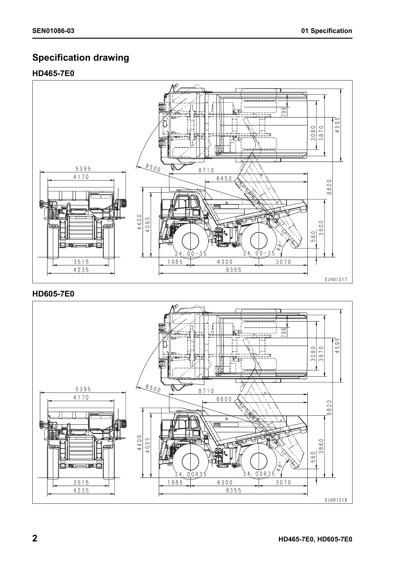
The opening specification chapter sets out the working envelope of both trucks side by side. It carries the dimensional drawings for the HD465-7E0 and the HD605-7E0 with overall length, width, height, wheelbase, tread and ground clearance called out, plus the full performance sheet: empty, maximum load and gross weight, weight distribution front and rear, struck and heaped body capacity, maximum travel speed, gradeability, minimum turning radius and dumping angle. The engine, power train, steering, suspension, tyre, brake and hydraulic cylinder specifications follow, along with a component weight table for rigging and a fuel, coolant and lubricant chart keyed to ambient temperature ranges.
10 Structure, Function and Maintenance Standard
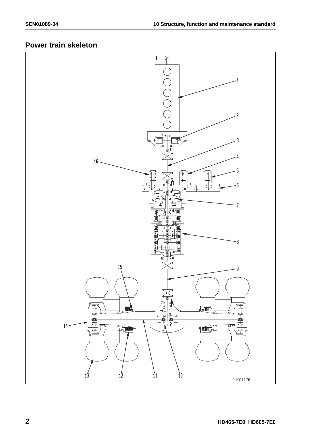
This is the largest technical block in the HD465-7E0 / HD605-7E0 shop manual and it is split across the individual form numbers that make up the binder. Engine and cooling system covers the radiator, torque converter oil cooler, aftercooler, work equipment oil cooler and fuel cooler, the fuel system, the brake oil cooler and the output shaft assembly with its maintenance standard table for flywheel, bearing and spline clearances. Power train Part 1 walks through the power train skeleton, front and rear drive shafts, torque converter and transmission hydraulic piping, the brake cooling oil control valve (BCV), the torque converter itself, the torque converter valve, the TORQFLOW transmission and its control valve, and the ECMV with its fill switch and proportional solenoid characteristics. Power train Part 2 covers the axle, differential, final drive and wheels with backlash and side-clearance limits.
Steering system documents the steering column, steering shaft, lock lever, yoke, joint shaft and steering linkage, with the clearance table for every bushing and pin in the knuckle arm, tie rod, centre lever and A-frame. Brake system is unusually complete: brake piping, brake valve, secondary brake valve, relay valve, front brake cut-off valve, accumulator charge valve, accumulators, slack adjuster, front disc brake, rear oil-cooled multiple disc brake, parking brake solenoid valve and the retarder circuit. Undercarriage and frame covers front and rear suspension cylinders, radius rods and the A-frame, including the automatic suspension specification with its damping force selector. Hydraulic system runs from the steering and hoist piping through the hydraulic tank, steering valve, crossover relief valve, steering cylinder, steering control valve, hoist valve, dump control valve (EPC valve), hoist cylinder and the gear pumps. Work equipment (Body) adds the auto greasing system with its flow divider valves and electric grease pump. Cab and its attachments covers the ROPS cab, air conditioner and rear view monitor. Electrical system Parts 1 through 4 cover the machine monitor system, automatic shift control, transmission controller, external power supply heater, automatic emergency steering, automatic suspension, retarder control, battery disconnector switch, dump control lever, VHMS controller, ASR system and the full sensor and switch inventory.
20 Standard Value Table
This chapter is where the manual earns its place on the workshop bench. It gathers the engine and machine standard service values into one reference: high idle, low idle and rated speed, intake air (boost) pressure, exhaust temperature and Bosch smoke index limits, valve clearance, compression pressure, blow-up pressure, engine oil pressure and oil temperature, plus travel speed at every gear, automatic shift-up and shift-down points in power, economy, coasting and braking modes, torque converter stall speed, lock-up set and reset speeds, overrun prevention brake thresholds, operating forces and strokes, and the full oil pressure table for torque converter, transmission, clutch control valves, lubricating valve, steering, hoist, dump EPC, accumulator charge valve, front and rear service brake, retarder and parking brake release. Braking distances, stopping distances, suspension cylinder installed lengths and pressures, tyre inflation pressures and hydraulic drift limits are all listed.
30 Testing and Adjusting
Five testing and adjusting forms walk through the measuring procedures step by step. Part 1 covers the engine side: engine speed, air supply (boost) pressure, exhaust temperature, exhaust gas colour with both the handy smoke checker and the smoke meter, valve clearance adjustment with the barring procedure and cylinder-by-cylinder valve arrangement, compression pressure with injector removal and reinstallation torques, blow-up pressure, engine oil pressure, EGR and bypass valve drive oil pressure, the fuel system handling precautions, residual pressure release, fuel pressure and return rate testing, air bleeding from the fuel circuit and fan belt and alternator belt replacement. Part 2 handles the power train and chassis side: torque converter stall speed, power train oil pressure at eleven test points, transmission speed sensor adjustment, brake oil pressure including the accumulator charge valve cut-in and cut-out, accumulator nitrogen gas pressure testing and charging with the ambient temperature correction table, brake performance testing, bleeding the brake circuit, front brake pad and rear brake disc wear checks, emergency parking brake release, front and rear suspension cylinder testing and adjusting including the automatic suspension specification, steering and hoist circuit pressures, dump EPC circuit pressures, steering cylinder air bleeding, emergency body raising and lowering, body positioner sensor adjustment and the electrical failure escape procedures. Parts 3, 4 and 5 cover device setting and adjustment, the special functions of the machine monitor (EMMS) service mode, real-time monitoring code tables, reduced cylinder mode, no-injection cranking, the transmission ECMV current adjustment and initial learning procedure, filter and oil replacement interval setting, ORBCOMM terminal opening, VHMS controller initial setting, KOMTRAX functions, Pm Clinic check sheet and payload meter initial settings.
40 Troubleshooting
The troubleshooting block is the strongest part of this Komatsu dump truck repair manual. It begins with a failure code table and fuse locations, then a general troubleshooting guide, then nine separate parts of troubleshooting by failure code — transmission double engagement, clutch slip and fill switch codes, clutch solenoid output circuit codes, parking brake drag, accumulator oil pressure reduction, filter clogging, engine controller codes CA111 through CA2556, common rail pressure codes, injector circuits, EGR and bypass valve servo codes, KOMNET data link timeout, and all the monitor and controller codes DAF9KM through DXHHKY. Each code entry lists the contents of the trouble, the controller action, the problem that appears on the machine, related information, and a numbered cause table with the exact resistance, voltage or continuity value to expect at each connector pin.
Alongside the code-based troubleshooting there are three further modes: E-mode for the electrical system with sixteen symptom-driven flowcharts covering engine no-start, automatic preheating, machine monitor display faults, alarm buzzer faults, gauge and caution lamp faults, power mode selection, AISS, seat belt caution lamp, turn signal and hazard lamps, night illumination, emergency steering, hoist lever and electric priming pump; H-mode for the hydraulic and mechanical system with seventeen symptoms covering no-travel, hunting, lock-up not cancelling, shift shock, no upshift, power loss, excessive shift lag, high torque converter oil temperature, low torque converter oil pressure, ineffective front and rear brakes, heavy or dead steering, steering vibration, slow body lift, no body movement and hydraulic drift; and S-mode for the engine with seventeen symptoms covering poor starting, no-start, poor pick-up, stalling, rough running, low output, black exhaust, oil consumption, dirty oil, high fuel consumption, coolant in oil, low oil pressure, rising oil level, overheating, abnormal noise, vibration and inability to bleed the fuel circuit.
50 Disassembly and Assembly
This is the hands-on section. It opens with general information on how to read the procedures, a coating materials list with Komatsu part numbers for adhesives, gasket sealants, greases and primers, and a special tool list with sketches. From there it works through fuel supply pump removal and installation with the high-pressure piping handling precautions, fuel injector removal and installation, cylinder head removal and installation with the cylinder head bolt tightening sequence and angular retightening values, engine front and rear seal removal and installation with the standard and sleeved seal selection procedure, engine assembly removal and installation with the centring procedure, radiator removal and installation with the hose clamp positions, output shaft removal and installation, brake and power train oil cooler removal and installation. Power train Part 1 covers torque converter and transmission removal, separation of the transmission and torque converter, disassembly of the torque converter, full transmission disassembly and assembly with clutch pack stroke checks, and ECMV removal, disassembly and assembly with the shim stack figures. Power train Part 2 covers differential removal and assembly including bearing preload, backlash and tooth contact adjustment, final drive carrier removal and assembly, and front wheel hub assembly. Steering, brake, undercarriage, hydraulic, body, cab and electrical forms complete the section with the front brake caliper, rear brake and parking brake assembly procedures, front and rear suspension cylinder overhauls, hoist cylinder overhaul, dump body removal with the body mount shim adjustment procedure, operator seat, air conditioner unit, and engine, transmission and retarder controller removal.
90 Diagrams and Drawings
The final chapter carries the full hydraulic diagrams and drawings — power train hydraulic circuit, steering and hoist hydraulic circuit (with the early and later serial number variants), and brake hydraulic circuit including the ASR specification — plus the electrical diagrams and drawings covering the cab interior in three sheets, the exterior in three sheets, the VHMS circuit, the ASR circuit, the air conditioner circuit, the auto greasing circuit, the external power supply heater circuit, and a connectors table with arrangement drawing listing every connector number, type, pin count, location and grid address.
Why This Compilation Matters
Because the truck is built around a 23.15 litre SAA6D170E-5 six-cylinder engine rated at 533 kW / 2,000 rpm with 3,324 Nm of torque at 1,400 rpm, a TORQFLOW planetary transmission with seven forward and one reverse speed, a 3.538 differential and a 4.737 final drive, the tolerances matter. A clutch fill time that drifts, a main relief valve that sits 0.2 MPa low, or a lock-up reset point that has moved off 1,050 rpm will show up as shift shock, clutch wear or a hot torque converter long before it shows up as a breakdown. The standard value table and the testing and adjusting procedures exist precisely so those drift conditions can be caught on a service day rather than on a haul cycle. The troubleshooting section then connects what the operator reports back to the specific pin, solenoid or sensor that failed, so a fault on a haul truck can be narrowed down to a connector rather than to a system.
Everything You Need, Delivered Instantly
IMAGES PREVIEW
This Komatsu HD465-7E0 and HD605-7E0 shop manual PDF gives you the full factory service information set in one file: specification, structure and function, maintenance standard values, all five testing and adjusting parts, the complete failure code and symptom-based troubleshooting library, disassembly and assembly procedures with tightening torques and coating materials, and the hydraulic and electrical circuit diagrams. Whether the job is a routine valve clearance adjustment, a transmission clutch pack overhaul, a brake accumulator recharge, a torque converter stall diagnosis or a fault code that will not clear, the procedure and the numbers are here. The download is delivered instantly after payment — no shipping, no waiting. The PDF opens on any laptop, tablet or phone in the workshop, and every page can be printed for the bench or the cab.
Reviews
There are no reviews yet.