
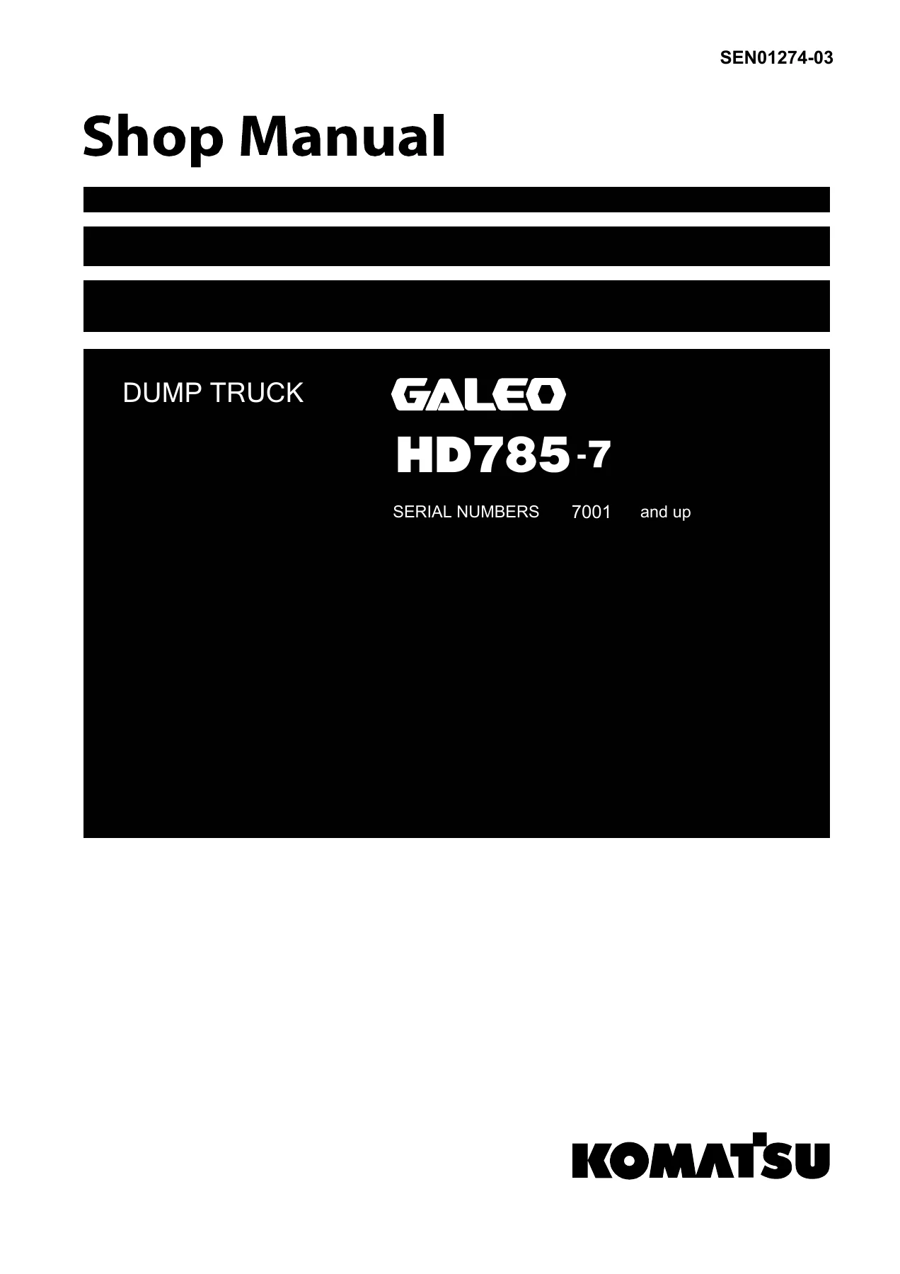
Komatsu HD785-7 Dump Truck Shop Manual SEN01274-03 – Complete PDF Service, Repair & Troubleshooting Guide
Original price was: $84.95.$54.95Current price is: $54.95.
The full Komatsu HD785-7 GALEO dump truck shop manual (SEN01274-03) covering serial numbers 7001 and up. 1,437 pages of engine, power train, brake, hydraulic, electrical, testing, troubleshooting, and disassembly procedures, plus wiring and hydraulic diagrams — delivered instantly as a PDF.
Description
Komatsu HD785-7 GALEO Dump Truck Shop Manual – SEN01274-03
This is the complete Komatsu HD785-7 dump truck shop manual, published under form number SEN01274-03 and covering machines from serial number 7001 and up. It is the same multi-section workshop reference Komatsu technical staff use in the field: a structured body of specification tables, structure-and-function write-ups, testing and adjusting procedures, failure-code driven troubleshooting, and step-by-step disassembly and assembly instructions that run from the engine and cooling system all the way through the final drive, cab electronics, and hydraulic circuit drawings.
At just under one thousand five hundred pages, this is not a quick-reference sheet — it is the full HD785-7 service library in a single PDF, and it is written for technicians who need real values, real procedures and real wiring and hydraulic diagrams rather than summaries.
File Details
- Manual type: Shop Manual (service, repair, testing, troubleshooting and overhaul)
- Brand: Komatsu
- Model: HD785-7 (GALEO)
- Serial numbers: 7001 and up
- Document number: SEN01274-03
- Language: English
- Page count: 1,437
- File format: PDF
- Published: 04-07 (02) — April 2007
Chapters Covered
- 00 Index and Foreword
- 01 Specification
- 10 Structure, Function and Maintenance Standard
- 20 Standard Value Table
- 30 Testing and Adjusting
- 40 Troubleshooting
- 50 Disassembly and Assembly
- 90 Diagrams and Drawings
Engine and Cooling System
The engine section covers the SAA12V140E-3 power plant — a 4-cycle, water-cooled V12 with direct injection, turbocharger and aftercooler, 140 mm × 165 mm bore and stroke, and 30.5 L displacement. It documents the radiator, brake and torque converter oil cooler, aftercooler, and the steering and hoist oil cooler assembly, along with the full fuel system including the common rail layout, supply pump, feed pump, fuel cooling plate and dual fuel filtration with water separator. The cooling-stack specifications give radiator core type, total radiation surface, and air-conditioner refrigerant charge so the technician can confirm the system is working against the factory figure, not a guess.
Power Train (Parts 1 & 2)
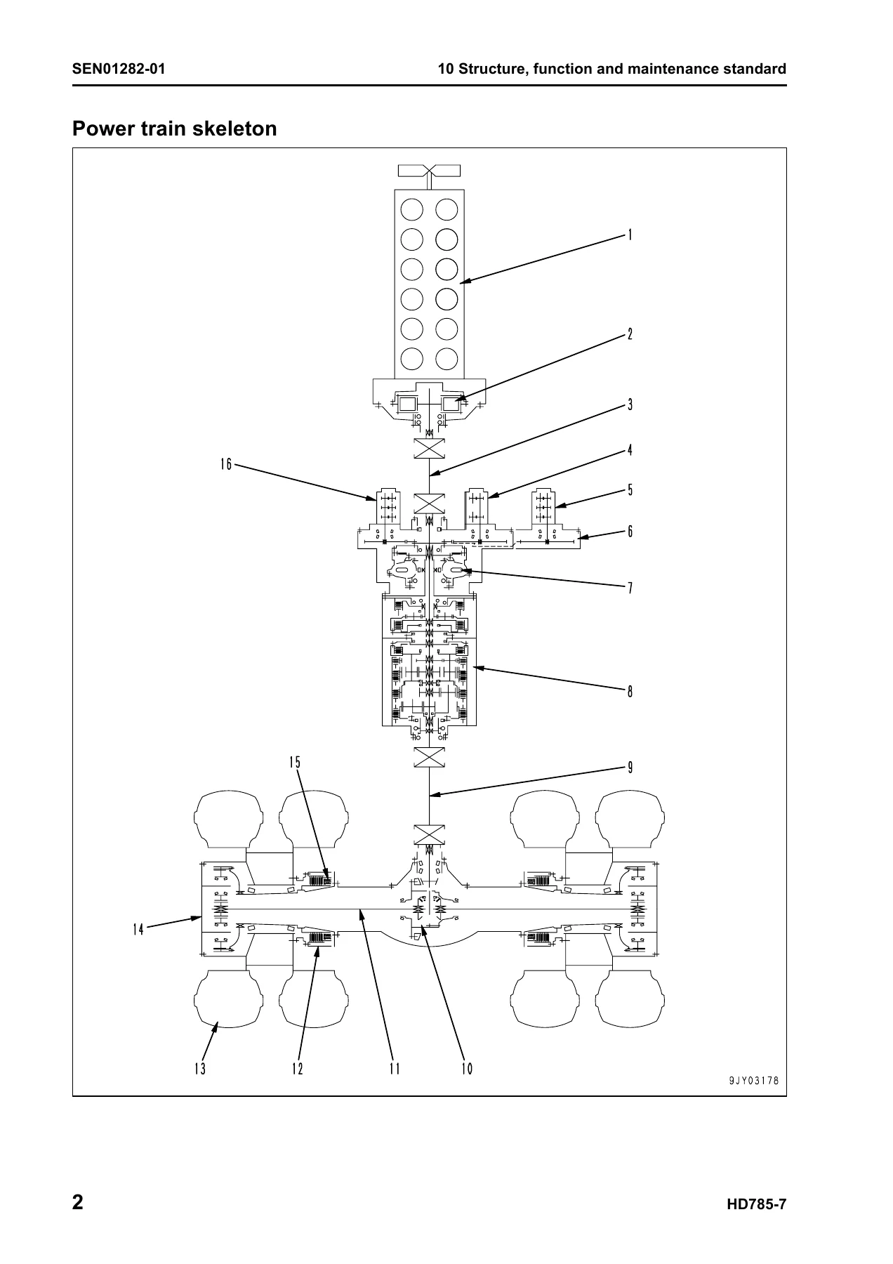
Power train coverage is split into two very detailed halves. Part 1 works through the output shaft, front and rear drive shafts, the 3-element 1-stage 2-phase torque converter with lock-up clutch, torque converter valve, the TORQFLOW planetary transmission with its seven forward and two reverse speeds, transmission control valve, ECMV modules, and the lubricating oil amount selector valve. Reduction ratios, clutch/plate counts, and transmission hydraulic piping are all laid out. Part 2 moves to the axle, spiral bevel differential, planetary final drive with 6.333 reduction ratio, wheels, and the oil-cooled multiple-disc brakes with their separate parking brake mechanism. Backlash values, thrust washer thicknesses, seal ring wear limits and clearance limits are given per component.
Steering System and Brake System
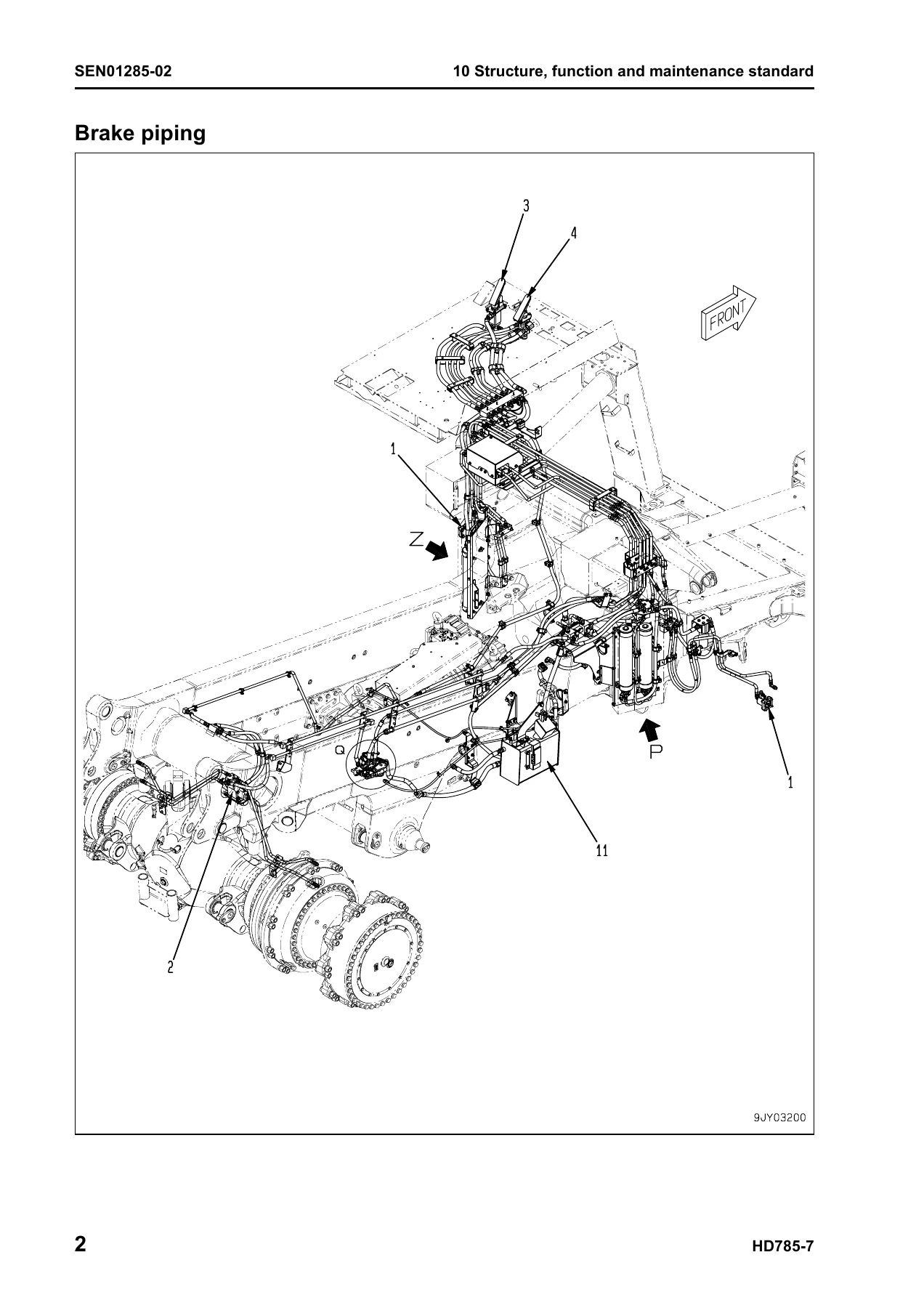
The steering chapter covers the steering column, linkage, and the fully hydraulic steering circuit, with the crossover relief valve and steering control valve explained in both schematic and operating description form. The brake chapter is unusually complete: brake piping, the two-portion service brake valve with its upper and lower spool logic, secondary brake valve, accumulator charge valve with cut-in at 11.8 MPa and cut-out at 20.6 MPa, nitrogen-charged accumulators (4,000 cc at 6.9 MPa), slack adjusters, front and rear oil-cooled multiple-disc brakes, parking brake release, the parking brake solenoid, retarder control solenoid, and the exhaust brake with its pressure reducing valve and switch. Brake actuating pressures for both service (9.8 ± 0.69 MPa) and retarder (6.4 MPa) operation are tabulated.
Undercarriage, Frame and Suspension
The MacPherson-type front and hydropneumatic rear suspension systems are documented with cylinder installed lengths, repair limits, and bushing clearances. The section covers the front suspension cylinder with its nitrogen gas chamber and valving, the rear suspension cylinder with its separate oil and gas chambers, the radius rods and A-frame, and the axle-to-frame mounting. Auto-suspension specifications are called out where fitted, including the variable damper valve with SOFT / MEDIUM / HARD modes and their respective cylinder lengths.
Hydraulic System
The hydraulic system chapter is one of the largest in the manual. It covers the steering and hoist hydraulic piping, high-pressure and low-pressure steering/hoist filters, the dump body control with body positioner sensor, the hydraulic tank with its filters, breather and bypass valve (156 L capacity), the steering valve, crossover relief valve, steering cylinder, steering control valve, hoist valve, dump control valve (EPC valve), hoist cylinder, and the full pump set — steering/hoist SAR(4)180+180+(1)6, brake cooling SAR(4)180+100, and torque converter/transmission/brake SDR(30)100+100+SA(1)25. Standard clearances, delivery volumes, relief pressures and rotating torques are specified for each pump.
Cab, Attachments and Electrical Systems (Parts 1–4)
The ROPS cab, air conditioner system (with refrigerant flow, condenser, receiver dryer, compressor specs and torque table for every refrigerant fitting), rear view monitor and controller layout are covered. Electrical coverage is then spread across four parts: machine monitor system, automatic shift control, automatic emergency steering, automatic suspension, retarder control, dump control lever, VHMS controller (including the Orbcomm option and payload meter logic), ABS/ASR system with wheel-speed sensor and control valve detail, altitude setting function, and a dedicated final part for sensors and switches — accelerator sensor, retarder/steering oil temperature sensors, coolant level sensor, fuel level sensor, filter clogging sensors, body positioner, steering angle sensors, accumulator oil pressure sensors, tilt switch, suspension pressure sensors, wheel speed sensors, blow-by sensor, exhaust temperature sensor, and ambient temperature sensor.
Standard Value Table
The standard value table lays out every machine and engine check value in one place: travel speed per gear, shift-up and shift-down points for power, economy and braking modes, lock-up set and reset speeds, overrun prevention brake points, torque converter stall speeds by mode, operating forces and strokes for pedals and levers, torque converter and transmission oil pressures per clutch, tire pressure, accumulator nitrogen pressures, brake stopping distances, suspension cylinder lengths and pressures, steering effort and turning time, and dump body lift, lower and hydraulic drift figures. This is the go-to reference when checking a rebuilt machine against the factory baseline.
Testing and Adjusting (Parts 1–5)
Testing and adjusting opens with the tool list and then walks through engine speed, boost pressure, exhaust temperature, exhaust gas colour, valve clearance, compression pressure, blow-by pressure, engine oil pressure, fuel pressure and fuel system leak checks, plus reduced cylinder mode and no-injection cranking. Part 2 handles torque converter stall speed, power train oil pressures, transmission speed sensor adjustment, brake oil pressure, accumulator nitrogen charging, brake performance, air bleeding for brake and ASR circuits, brake disc wear, emergency parking brake release, front and rear suspension cylinder adjustment, steering and hoist circuit pressure, dump EPC circuit pressure, and steering cylinder air bleeding. Later parts cover the special functions of the machine monitor (EMMS), the VHMS controller initial setting procedure, payload meter setup, and a complete Pm Clinic check sheet.
Troubleshooting (Failure Codes, E-Mode, H-Mode, S-Mode)
Troubleshooting is organised both by failure code and by symptom. The failure code table lists several hundred codes with their applicable controller (machine monitor, engine, transmission, retarder, ABS, VHMS), action code, and history classification, and then each code is individually documented with contents of trouble, controller action, machine symptom, related information, possible causes and standard values in the normal state. The E-mode covers electrical system troubleshooting from engine no-start through to hoist lever problems; the H-mode covers hydraulic and mechanical faults (hunting, lockup, shift quality, brake effectiveness, steering, dump body); and the S-mode covers engine symptoms (poor starting, black smoke, oil consumption, coolant loss, oil pressure drop and overheating).
Disassembly and Assembly
The disassembly and assembly section is written for the workshop: special tools, adhesive list, and then component-by-component procedures. Engine and cooling system work includes fuel supply pump, cylinder head, radiator and engine assembly. Power train Part 1 covers front drive shaft, torque converter and transmission removal and connection, torque converter and PTO assembly, and the complete transmission assembly. Power train Part 2 covers the differential, front brake assembly and rear brake assembly. Torque values, coating materials and component weights are printed in each step.
Diagrams and Drawings
The final section contains the power train hydraulic circuit diagram, steering and hoist hydraulic circuit diagram, and four brake hydraulic circuit variations — base, ASR specification, ABS specification, and combined ASR/ABS specification. The electrical diagrams cover outside-cab and inside-cab circuits, VHMS, ABS, and ASR, and close with a full connector table with pin counts, connector types, locations and 3D drawing addresses.
What This Manual Lets You Do
With this HD785-7 shop manual in hand you can service and overhaul the truck to Komatsu’s own procedures. That means correctly setting shift points and lock-up behaviour, diagnosing a retarder fault from the failure code table instead of by trial and error, tearing down and rebuilding the transmission or final drive with the exact torque figures and clearance limits, bleeding the brake or ASR circuit, charging the suspension cylinder with nitrogen, adjusting the body positioner sensor, or restoring the machine monitor after a controller replacement. Testing and adjusting procedures are paired with the standard value table, so every measurement has a matching target value.
For workshops that keep more than one HD785-7 in service, this is the difference between a repair that holds and a repair that comes back. The troubleshooting-by-failure-code approach is especially valuable — every code comes with the wiring-level checks, connector pin numbers, resistance and voltage values, and the possible causes ranked with their own standard values. That is the pattern that saves hours on intermittent electrical faults.
Why It Matters
Komatsu’s HD785-7 is a 163,300 kg gross weight machine with a 91,000 kg payload, and the components it uses — the SAA12V140E-3 engine, the TORQFLOW transmission, the oil-cooled disc brakes, the hydropneumatic suspension — all have specific clearances, pressures and torque values that, if ignored, produce failures down the line. The standard value table and the maintenance standard tables in the structure chapter exist exactly so that a rebuilt component can be measured against the original tolerance range, not the technician’s experience of a similar machine. Using the printed figure is the only reliable way to keep a truck of this size inside its design envelope.
Delivery
IMAGES PREVIEW
The manual is delivered as an instant PDF download. No shipping, no waiting for a courier. It opens on any device — laptop, tablet, or shop-floor desktop — and pages can be printed for the workshop if you prefer hard copy for a specific procedure. Because the full file is over one thousand pages, we recommend keeping a working copy on a shop computer and printing only the sections you need on the day.
Reviews
There are no reviews yet.