
Komatsu HM400-2 Articulated Dump Truck Shop Manual SEN00239-09 – 2001 & Up PDF
Original price was: $59.95.$39.95Current price is: $39.95.
Complete Komatsu HM400-2 shop manual (SEN00239-09) covering every service system on 2001 and up articulated dump trucks – 1,463 pages of specifications, troubleshooting, testing and adjusting, disassembly and assembly, plus hydraulic and electrical diagrams.
Description
This Komatsu HM400-2 Articulated Dump Truck Shop Manual is the full service reference for machines from serial number 2001 and up. Issued by Komatsu under Form No. SEN00239-09, it compiles every service discipline for the HM400-2 into a single 1,463-page document – engine and cooling, power train, steering, brake, undercarriage and frame, hydraulic, cab, and the complete electrical system including the payload meter. Whether you are performing scheduled maintenance, diagnosing an electrical fault code, overhauling a transmission, or rebuilding a differential, this HM400-2 shop manual gives you the procedures, the standard values, and the diagrams that go with them.
File Details
- Manual type: Shop Manual
- Brand: Komatsu
- Model: HM400-2
- Serial numbers: 2001 and up
- Form No.: SEN00239-09
- Language: English
- File format: PDF
- Page count: 1,463 pages
- Publication date: 01-09 (02)
Chapters Covered
- 00 – Index and Foreword
- 01 – Specification
- 10 – Structure, Function and Maintenance Standard
- 20 – Standard Value Table
- 30 – Testing and Adjusting
- 40 – Troubleshooting
- 50 – Disassembly and Assembly
- 90 – Diagrams and Drawings
00 – Index and Foreword
Safety notices, the method for reading the manual, an explanation of the terminology used in the maintenance standards, and the handling precautions for electrical equipment and hydraulic components. This section also covers the newer connector types used on engines, how to read the electric wire codes, the standard tightening torque tables, and the conversion tables you will need when moving between SI and conventional units.
01 – Specification
Specification drawings, the full machine specification set, the weight table for individual components, and the fuel, coolant, and lubricant recommendations. If you need to know the HM400-2’s operating weight, its rated payload, or which oil grade is specified at a given ambient temperature, it is here.
10 – Structure, Function and Maintenance Standard
This is the largest block of the HM400-2 shop manual and covers the structure and function of each system, together with its maintenance standard values and clearances. Systems included are:
- Engine and cooling system – radiator, oil cooler, aftercooler, and output shaft
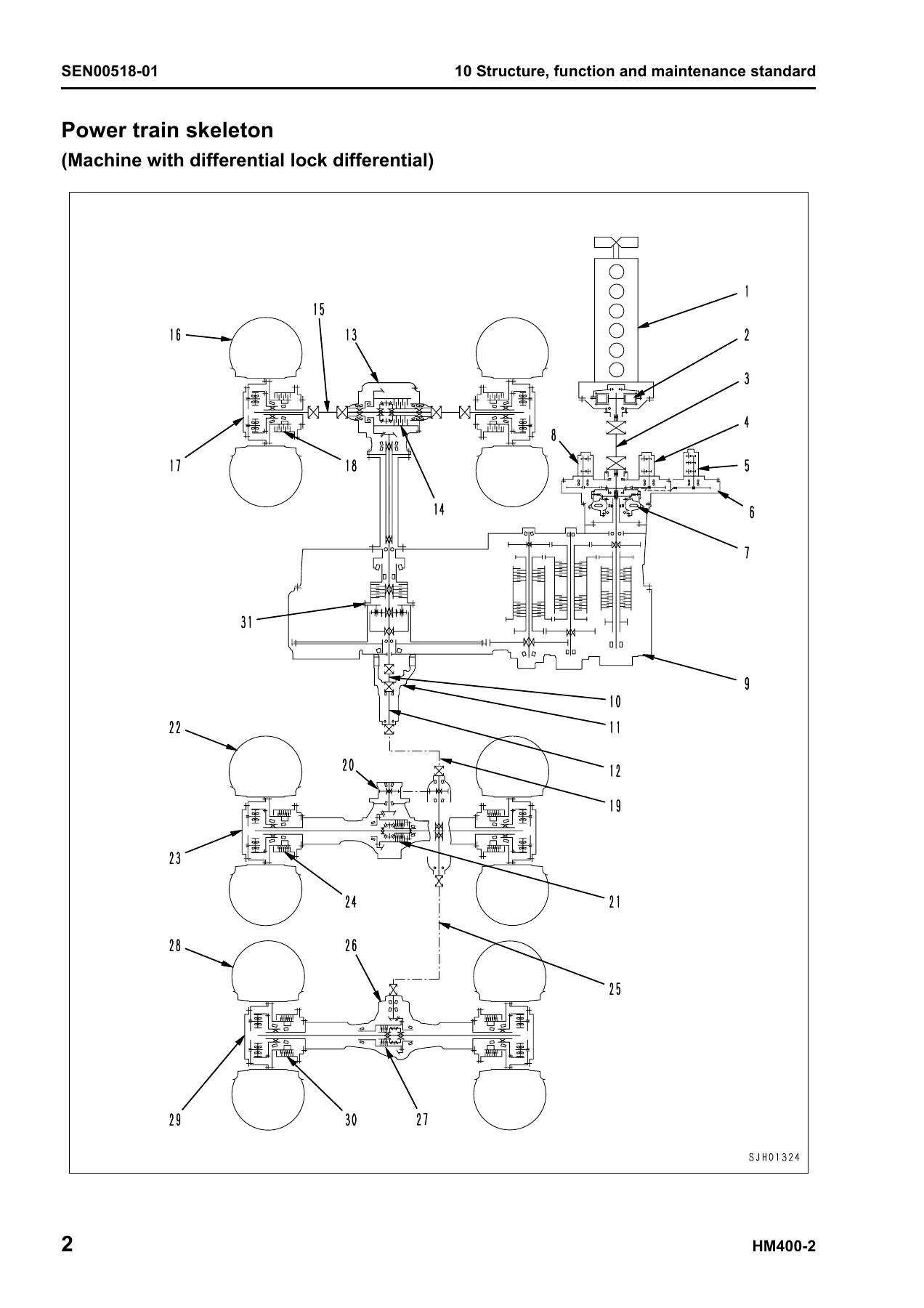
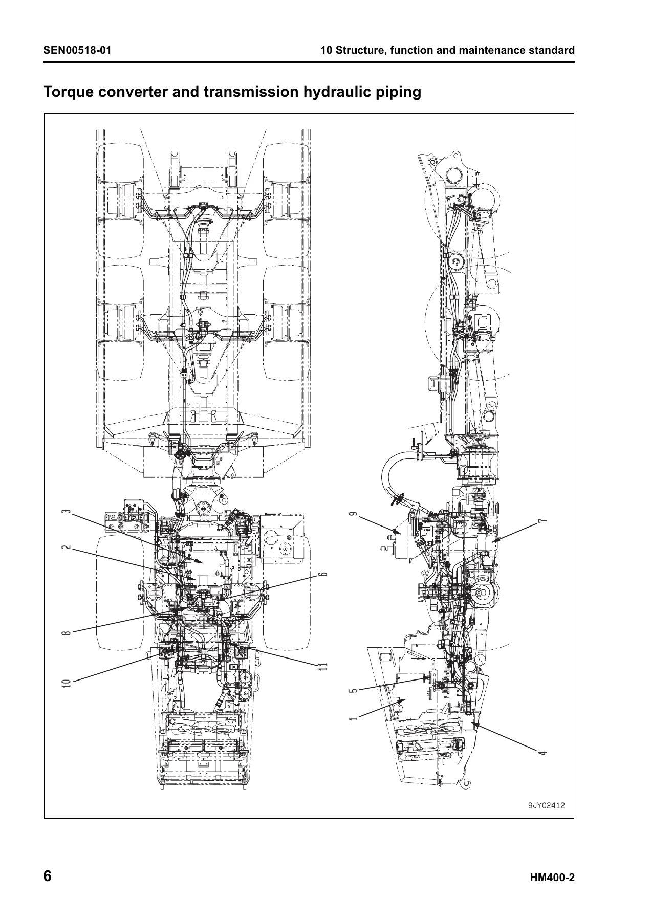
- Power train Part 1 – power train skeleton, torque converter and transmission hydraulic piping, brake cooling oil control valve (BCV), power train pump, torque converter, transmission, transmission control valve, ECMV, main relief and torque converter relief valves
- Power train Part 2 – drive shaft, axle, differential, limited slip differential, final drive
- Steering system – steering column
- Brake system – brake piping, brake valve, accumulator charge valve, accumulator, slack adjuster, brake, parking brake, proportional reducing valve, parking brake solenoid valve
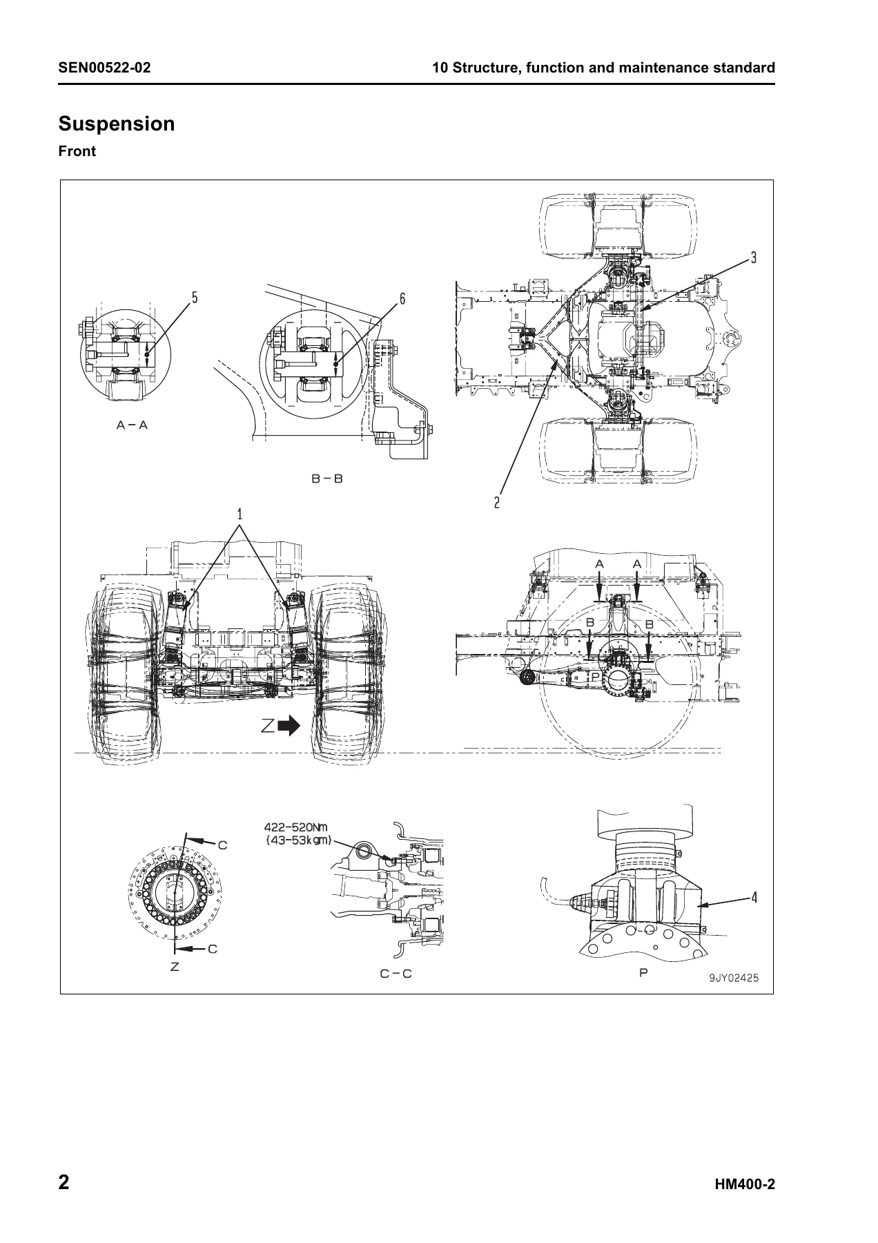
- Undercarriage and frame – suspension cylinder, equalizer bar, hitch frame
- Hydraulic system – steering and hoist oil pressure piping, dump body control, hydraulic tank and filter, flow amplifier valve, steering valve, steering cylinder, hoist valve, dump control valve (EPC), pilot check valve, hoist cylinder, hydraulic pump
- Cab and its attachments – ROPS cab, cab tilt, air conditioner, rear view monitor, controllers
- Electrical system Part 1 – machine monitor system
- Electrical system Part 2 – automatic shift control, transmission controller, retarder control system, auto emergency steering, battery disconnector switch, dump control lever
- Electrical system Part 3 – payload meter (card type)
- Electrical system Part 4 – sensors, switches, and the KOMTRAX terminal system
Each system is presented with structure and function explanations, exploded component views, oil flow diagrams, and maintenance standard tables showing standard size, tolerance, standard clearance, and clearance limit. This is the section you will return to when checking whether a worn part is still within service.
20 – Standard Value Table
The standard service value tables for engine and chassis in one place. Engine values include idle speeds, rated rpm, torque converter stall, exhaust temperature, valve clearance, compression pressure, blow-by pressure, oil pressure, and belt tensions. Chassis values include accelerator pedal effort and stroke, lockup activation and deactivation speeds, transmission shift-up and shift-down speeds, overrun prevention activation and deactivation, gearshift lever operating effort, and the full set of power train oil pressures, brake pressures, steering relief pressure, suspension cylinder lengths and pressures, and dump circuit times and hydraulic drift limits.
30 – Testing and Adjusting
Three testing and adjusting parts walk you through the practical measurement and adjustment procedures with the correct tools, measurement conditions, and limits. Part 1 covers engine and cooling (engine speed, intake air/boost pressure, exhaust temperature and color, valve clearance, compression, blow-by, engine oil pressure, EGR valve and bypass valve drive oil pressure, fuel system handling, fuel pressure, fuel return and leakage, air bleeding, fan/alternator/air conditioner belt tensions). Part 2 covers power train and chassis (torque converter stall, power train oil pressure, differential lock oil pressure, transmission speed sensor adjustment, brake oil pressure, accumulator nitrogen gas pressure and charging, brake performance, brake air bleeding, wheel brake disc wear, parking brake pad wear, parking brake emergency release, steering oil pressure, suspension cylinder, cab tilting, dump circuit oil pressure, body positioner sensor, and emergency escape at electrical system failure). Part 3 covers setting and adjustment of various equipment, the special functions of the machine monitor, KOMTRAX terminal start-up, and the initial setting of the payload meter.
40 – Troubleshooting
General troubleshooting guidance, the connection tables for connector pin numbers, and the full troubleshooting-by-failure-code coverage. Failure codes are broken into eight parts, and the general failure-code table lists every code with its action code, applicable equipment, and history classification. Beyond the code-driven tables, there are dedicated E-mode (electrical system), H-mode (hydraulic and mechanical), and S-mode (engine) troubleshooting charts for the symptoms that do not set a code – things like machine does not start, travel is not smooth, steering is heavy, dump body does not move, or coolant temperature becomes too high.
50 – Disassembly and Assembly
Removal, installation, disassembly, and assembly procedures for the major assemblies, together with special tool lists, tightening torques, and the coating materials, oils, greases, and coolants required for each job. Covered assemblies include the engine and cooling system, power train parts 1-3, undercarriage and frame, hydraulic system, cab and its attachments, and the electrical system controllers. This is the section to open when you are pulling a transmission, rebuilding a differential, replacing a final drive, or resealing a steering cylinder.
90 – Diagrams and Drawings
Hydraulic circuit diagrams for the power train, steering and hoist, brake, brake cooling, and differential lock circuits, plus the electrical circuit diagrams for the inside cab, outside cab, and payload meter, with a connectors table and arrangement drawing. These are the schematics that support everything in the testing, troubleshooting, and disassembly sections.
A Complete Service Reference for the HM400-2
IMAGES PREVIEW
With 1,463 pages of Komatsu’s own service information, this HM400-2 shop manual supports the full range of work on the machine – routine maintenance, scheduled service, fault diagnosis, component overhaul, and complete assembly removal and installation. Having the factory torque values, clearances, oil pressures, and diagnostic flow charts in front of you means fewer guesswork repairs, less risk of damaging tight-tolerance components, and a much better chance of fixing the problem once. The manual is delivered as an instant-download PDF after checkout, so there is no shipping and no waiting. Read it on a laptop, tablet, or phone in the workshop, or print the pages you need for the job in front of you. Whether you are a Komatsu technician, a fleet maintenance manager, an independent heavy-equipment mechanic, or an owner-operator who prefers to do the work yourself, this HM400-2 shop manual is the reference you want within reach.
Reviews
There are no reviews yet.