
Komatsu HM400-2 Articulated Dump Truck Shop Manual SEN00239-10 (2001 and Up) – Full PDF Service Guide
Original price was: $74.95.$49.95Current price is: $49.95.
Complete Komatsu HM400-2 Articulated Dump Truck Shop Manual (SEN00239-10) for serial numbers 2001 and up. 1,465 pages covering specifications, structure and function, standard values, testing and adjustment, troubleshooting, disassembly and assembly, and hydraulic/electrical diagrams.
Description
The Komatsu HM400-2 Articulated Dump Truck Shop Manual is the complete service documentation for machines serial number 2001 and up. Carrying Form No. SEN00239-10, this 1,465-page PDF is divided into eight major sections that take you from specification data and system theory straight through to failure-code diagnostics, teardown, and rebuild. Every procedure is tied to the HM400-2 and its SAA6D140E-5 engine, and every measurement is referenced back to the standard value tables so you can judge condition against a known baseline.
File Details
- Manual type: Shop Manual
- Brand: Komatsu
- Model: HM400-2 Articulated Dump Truck
- Serial numbers: 2001 and up
- Document number: SEN00239-10
- Language: English
- Page count: 1,465
- File format: PDF
- Date: 08-09
Chapters Covered
- Index and foreword
- Specification
- Structure, function and maintenance standard
- Standard value table
- Testing and adjusting
- Troubleshooting
- Disassembly and assembly
- Diagrams and drawings
Index and Foreword
The opening section establishes the manual’s conventions and safety framework. It covers the safety notice, how to read the shop manual, the terms used in maintenance standards, handling procedures for electrical equipment and hydraulic components, connector handling (including the newer engine connectors), electric wire code reading, general operation precautions, push-pull coupler disassembly and connection, standard tightening torque tables, and conversion tables. This is the section you read before touching the machine.
Specification
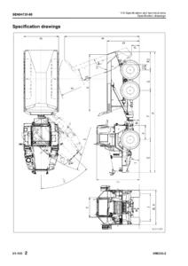
This section opens with the specification drawings and the full machine specification table. It gives you the dimensions, performance figures, weight data for major components, and the fuel, coolant and lubricant recommendations. Use it to confirm capacities and fluid types before a service job, or to verify a machine’s configuration before ordering parts.
Structure, Function and Maintenance Standard
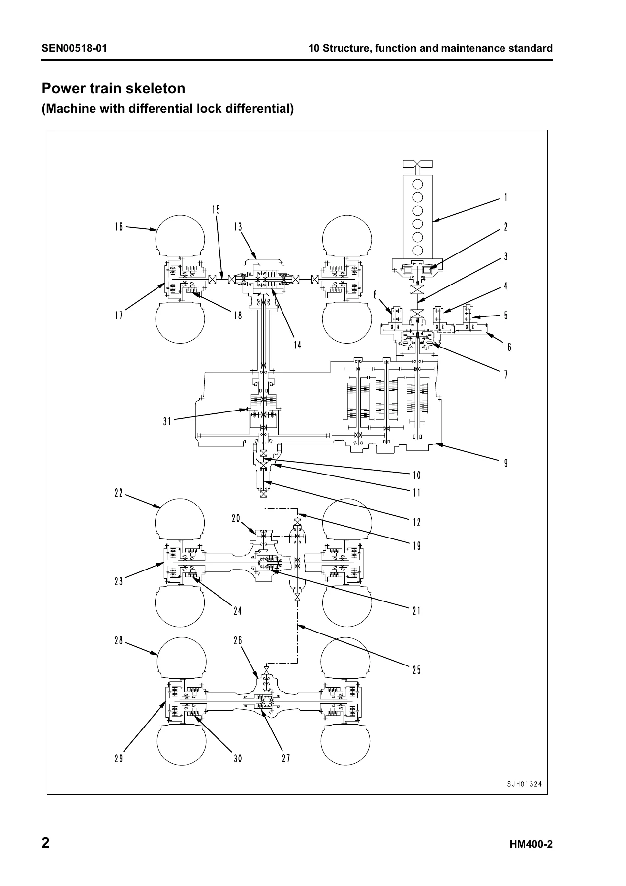
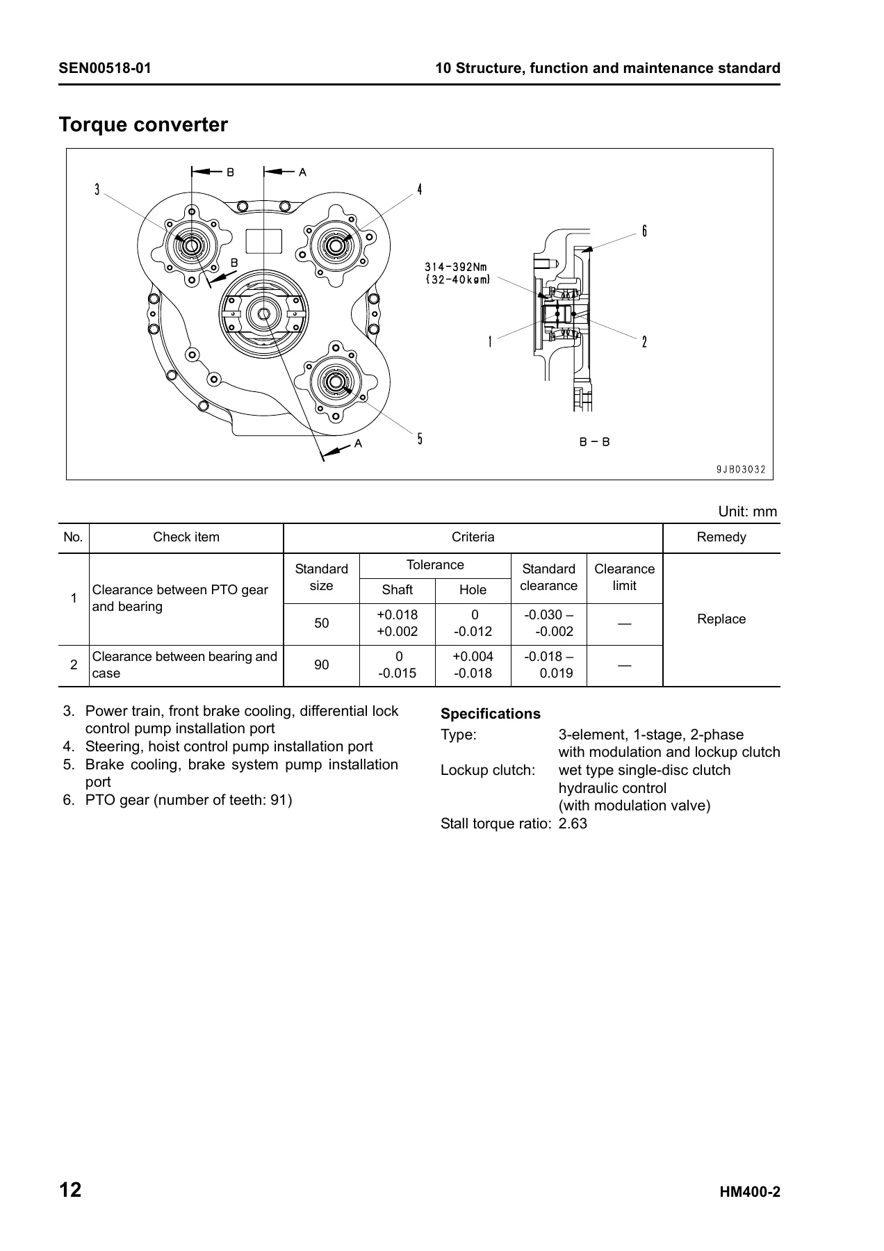
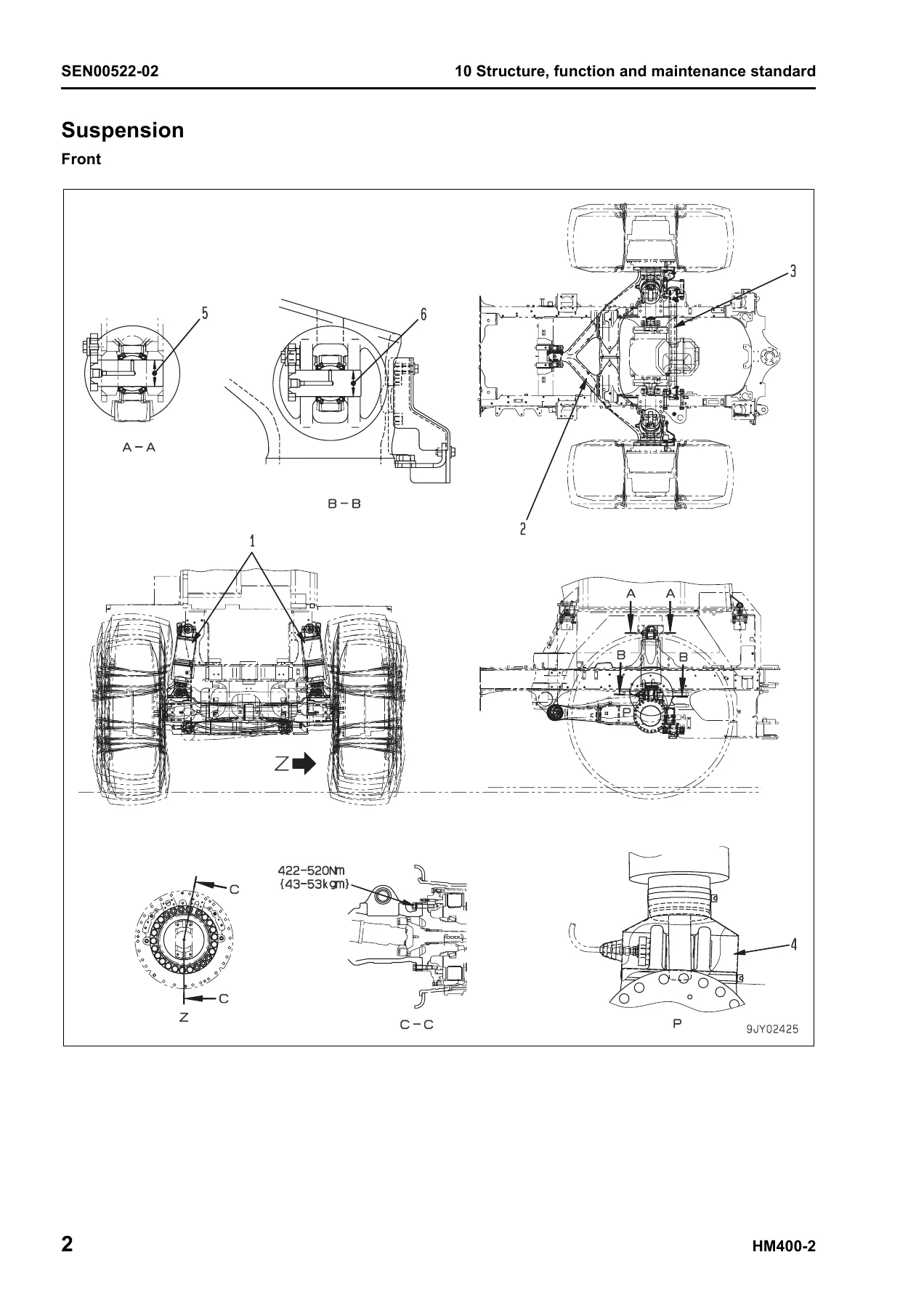
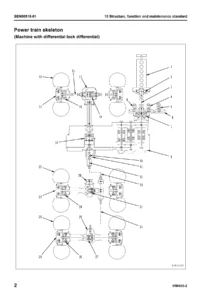
The largest section of the manual and the technical core of the book. It runs through every major system with both theory of operation and maintenance criteria. It opens with the engine and cooling system (radiator, oil cooler, aftercooler, output shaft), then moves into Power train Part 1 — the power train skeleton, torque converter and transmission hydraulic piping, brake cooling oil control valve, power train pump, torque converter, transmission, transmission control valve, ECMV, and main relief and torque converter relief valve. Power train Part 2 covers the drive shaft, axle, differential, limited slip differential, and final drive. The steering system section follows, then the brake system with its piping, brake valve, accumulator charge valve, accumulator, slack adjuster, brake, parking brake, proportional reducing valve, and parking brake solenoid valve. Undercarriage and frame content covers suspension cylinders, equalizer bar, and hitch frame. The hydraulic system section is extensive: steering and hoist piping, dump body control, hydraulic tank and filter, flow amplifier valve, steering valve, steering cylinder, hoist valve, dump control valve (EPC), pilot check valve, hoist cylinder, and hydraulic pump. Cab and attachments covers the ROPS cab, cab tilt, air conditioner, rear view monitor, and controller layout. The electrical system section runs through the machine monitor system, automatic shift control system, transmission controller, retarder control system, auto emergency steering system, battery disconnector switch, dump control lever, payload meter, sensors, switches, and KOMTRAX terminal.
Standard Value Table
Standard values for the engine and chassis, with permissible values and judgment criteria. This section sits alongside the testing and adjusting procedures — it is where you find the numbers that tell you whether a component is within specification or requires repair. The engine values cover speed, boost pressure, exhaust temperature, compression pressure, blow-by pressure, oil pressure, and more. Chassis values cover accelerator pedal effort, torque converter lockup speeds, transmission shift points, clutch pressures, travel speeds, tire inflation pressure, brake pressures, and steering relief pressure.
Testing and Adjusting
A full procedural section covering the tools and methods for measuring and adjusting every major system. It includes engine speed measurement, intake air pressure (boost), exhaust temperature and gas color, valve clearance, compression pressure, blow-by pressure, engine oil pressure, EGR valve and bypass valve drive oil pressure, handling of fuel system devices, releasing residual fuel pressure, fuel pressure, fuel return and leakage, bleeding air from the fuel circuit, fuel circuit leakage testing, fan/alternator/air conditioner belt tensions, torque converter stall speed, power train oil pressure, differential lock oil pressure, transmission speed sensor adjustment, brake oil pressure, accumulator nitrogen gas pressure testing and charging, brake performance testing, brake circuit bleeding, wheel brake disc wear, parking brake pad wear, emergency parking brake release, steering circuit oil pressure, suspension cylinder testing, cab tilting, dump circuit oil pressure, body positioner sensor adjustment, body heating spherical joint spring length, engine controller voltage circuit handling, transmission controller adjustment, emergency escape at electrical system failure, setting and adjusting various equipment, special machine monitor functions, KOMTRAX terminal operation, Pm Clinic check sheet, and payload meter initial setting.
Troubleshooting
The diagnostic section, organized into general information on troubleshooting, failure code tables (Parts 1 through 8), and three troubleshooting modes: E-mode for the electrical system, H-mode for hydraulic and mechanical systems, and S-mode for the engine. Failure code coverage includes transmission oil filter clogging, clutch abuse and slip codes, ECMV and pressure control valve issues, parking brake dragging, accumulator pressure warnings, engine oil and coolant conditions, and the full CA-series engine controller codes. E-mode walks through starting and preheating problems, machine monitor issues, gauge and lamp faults, turn signal and lighting circuits, backup lamp and buzzer faults, emergency steering, and the air conditioner. H-mode covers machine start problems, travel smoothness, lockup faults, shift shock and timing, travel speed and power, torque converter temperature, brake performance, steering, and dump body operation. S-mode covers engine starting, power, exhaust, oil consumption, coolant, oil pressure, overheating, noise and vibration. Each failure code entry gives the detection conditions, controller action, resulting machine behavior, possible causes, and the normal-state values or wiring checks used to isolate the fault.
Disassembly and Assembly
A complete teardown and rebuild reference. The general information section covers how to read the procedures, adhesives, and special tools. Engine and cooling system procedures include the fuel supply pump, engine assembly, cylinder head, fuel injector, radiator, cooling assembly, aftercooler, and front and rear seals. Power train Part 1 covers the output shaft, transmission and front differential, torque converter, and transmission. Power train Part 2 covers the front, center and rear differentials. Power train Part 3 covers the front, center and rear final drives and brakes, plus the center and rear axles. Undercarriage and frame covers suspension cylinders, equalizer bar, wheels, hitch frame, and body. Hydraulic system covers the steering valve, flow amplifier, hoist valve, steering cylinder, and hoist cylinder. Cab and attachments covers the operator’s cab, glass, seat, and air conditioner. Electrical system covers the retarder, transmission, and engine controllers. Each procedure notes the special tools, coating materials, tightening torques, and weight of the component being handled.
Diagrams and Drawings
Hydraulic circuit diagrams for the power train, steering and hoist, brake, brake cooling, and differential lock circuits. Electrical circuit diagrams for inside the cab, outside the cab, and the payload meter, plus the connector tables and arrangement drawings. These are the reference diagrams for tracing a circuit, confirming hose routing, or understanding how a system is laid out on the machine.
How the Sections Work Together
The manual is structured so that each phase of a repair references the others. A failure code in the troubleshooting section points to a component; the structure and function section explains how that component works; the testing and adjusting section gives the measurement procedure and standard value; the disassembly and assembly section gives the teardown sequence and torque specs; and the diagrams section provides the hydraulic or electrical circuit for that system. That cross-referencing is what makes the shop manual usable as a single-source reference rather than a collection of disconnected chapters.
What This Manual Supports
This manual supports the full range of work on the HM400-2: diagnosing a fault from a failure code, confirming wear or performance against standard values, adjusting a system after repair, tearing down and rebuilding major components with the right tools and torque values, and tracing a problem through the hydraulic or electrical circuit. The procedures are specific to the HM400-2 and its serial number range, and the specifications and torque values are printed as they apply to this machine. Whether you are servicing the SAA6D140E-5 engine, the torque converter and transmission, the front/center/rear differentials and final drives, the hydraulic hoist and steering circuits, or the brake system with its accumulators and slack adjusters, the manual gives you the sequence, the values, and the diagrams to do the job correctly.
IMAGES PREVIEW
Delivered as an instant PDF download with no shipping delay, the file opens on any device and the pages are printable for use in the shop. You get the complete 1,465-page shop manual in one file — no subscriptions, no missing sections, no separate purchases for the electrical or hydraulic diagrams. The Komatsu HM400-2 Articulated Dump Truck Shop Manual SEN00239-10 is the reference you keep on the shelf and reach for every time a fault code appears, a major component comes out, or a system needs to be brought back to specification.
Reviews
There are no reviews yet.